EP0140992B1 - Transducer element, method for its manufacture and its use in a pressure pick-up device - Google Patents
Transducer element, method for its manufacture and its use in a pressure pick-up device Download PDFInfo
- Publication number
- EP0140992B1 EP0140992B1 EP83111227A EP83111227A EP0140992B1 EP 0140992 B1 EP0140992 B1 EP 0140992B1 EP 83111227 A EP83111227 A EP 83111227A EP 83111227 A EP83111227 A EP 83111227A EP 0140992 B1 EP0140992 B1 EP 0140992B1
- Authority
- EP
- European Patent Office
- Prior art keywords
- plate
- diaphragm
- insulating
- transduction element
- base plate
- Prior art date
- Legal status (The legal status is an assumption and is not a legal conclusion. Google has not performed a legal analysis and makes no representation as to the accuracy of the status listed.)
- Expired
Links
Images

Classifications
-
- G—PHYSICS
- G01—MEASURING; TESTING
- G01L—MEASURING FORCE, STRESS, TORQUE, WORK, MECHANICAL POWER, MECHANICAL EFFICIENCY, OR FLUID PRESSURE
- G01L19/00—Details of, or accessories for, apparatus for measuring steady or quasi-steady pressure of a fluent medium insofar as such details or accessories are not special to particular types of pressure gauges
- G01L19/0061—Electrical connection means
- G01L19/0084—Electrical connection means to the outside of the housing
-
- G—PHYSICS
- G01—MEASURING; TESTING
- G01L—MEASURING FORCE, STRESS, TORQUE, WORK, MECHANICAL POWER, MECHANICAL EFFICIENCY, OR FLUID PRESSURE
- G01L19/00—Details of, or accessories for, apparatus for measuring steady or quasi-steady pressure of a fluent medium insofar as such details or accessories are not special to particular types of pressure gauges
- G01L19/06—Means for preventing overload or deleterious influence of the measured medium on the measuring device or vice versa
- G01L19/0627—Protection against aggressive medium in general
- G01L19/0645—Protection against aggressive medium in general using isolation membranes, specially adapted for protection
-
- G—PHYSICS
- G01—MEASURING; TESTING
- G01L—MEASURING FORCE, STRESS, TORQUE, WORK, MECHANICAL POWER, MECHANICAL EFFICIENCY, OR FLUID PRESSURE
- G01L19/00—Details of, or accessories for, apparatus for measuring steady or quasi-steady pressure of a fluent medium insofar as such details or accessories are not special to particular types of pressure gauges
- G01L19/14—Housings
- G01L19/147—Details about the mounting of the sensor to support or covering means
Definitions
- the invention relates to a transducer element with a membrane plate made of semiconductor material having at least one membrane region with at least one piezoresistor and an insulating plate on which the membrane plate is fastened.
- the invention further relates to methods for producing the transducer element and a pressure sensor using the transducer element.
- the measuring element of such pressure transducers is a plate, preferably made of silicon (Si) single crystal, arranged on an insulating substrate, such as glass, on which an elastic membrane region is formed, which is deflected under the measuring pressure acting on it.
- the resistors are attached or diffused into the membrane area, which are connected to full or half measuring bridges in a known manner.
- Silicon as a single crystal material has excellent mechanical properties in that it shows practically no signs of aging and wear. Silicon is therefore an ideal semiconductor material for the formation of the membrane plates, especially since it can be machined with high precision mechanically or chemically and has particularly good electrical properties.
- the main disadvantage of silicon is the temperature expansion coefficient, which is four to six times lower than that of the steels commonly used for the pressure transducer housing, in particular the austenitic corrosion-resistant steels. Therefore, temperature changes can easily lead to tension and warping of the Si membrane plates attached to such steels, which in turn e.g. Zero deviations can result.
- a piezoresistive pressure transducer based on a transducer element in which the Si membrane plate by an anodic connection, which requires heating in the temperature range of 360 ° C-500 ° C, on an insulating glass plate is attached. Since glass has a higher coefficient of expansion than silicon, the laminate from the two plates tends to tighten during cooling by placing the Si membrane plate laterally under compressive stress. In extreme cases, this can cause the membrane to "fold over" from one stable position to another (sleeve cover effect). Such instability, even when the extreme case is not reached, changes the slope or calibration curve in a highly undesirable manner and is the cause of various deviations from the linearity. In addition, the zero point is strongly dependent on the temperature.
- a piezoresistive pressure transducer based on a Si membrane plate is also known, which is attached to a mounting plate made of an Fe-Ni alloy via a thick soft solder layer.
- Soft solders have significantly higher coefficients of expansion than silicon and therefore also cause tensioning of the membrane plate when the temperature changes.
- such pressure transducers are not suitable for precision measurements.
- GB-A-20 80 541 describes a sensor with an Si membrane plate attached to one side of a gas plate.
- a tubular holder made of an Fe-Ni alloy is attached to the opposite side of the glass plate.
- the thermal expansion coefficients of adjacent components are matched to one another. Although it can be achieved with a certain composition of the Fe-Ni alloy that its thermal expansion coefficient largely corresponds to that of Pyrex glass, a perfect match cannot be achieved.
- pressure transducers can be produced in which there is no need to crack during the anodic connection, provided that certain upper temperature limit values are not exceeded, but the remaining differences in the coefficients of thermal expansion have the consequence that none with regard to the zero point constancy and measuring accuracy substantial improvement over other known arrangements can be achieved.
- the invention is based on the object of creating a converter element of the type mentioned at the outset which can be produced inexpensively and with high precision and in which temperature changes over a wide temperature range only go or none Result in tension in the measuring membrane.
- a base plate is attached to the surface of the insulating plate facing away from the membrane plates, which has a coefficient of thermal expansion which is essentially the same as that of the membrane plate and whose dimensions are matched to the dimensions of the membrane plate in such a way that the temperature change Deformation forces exerted by the membrane and base plate on the insulating plate are essentially the same in order to achieve a stress-symmetrical state.
- the deformation forces exerted by the two plates on the insulating plate are essentially the same sense; for example, if the temperature expansion coefficient of the semiconductor material is smaller than that of the insulation material, the temperature expansion coefficient of the material of the base plate should also be smaller than that of the insulation material.
- the base plate can also be anodically bonded to the insulator, or glass frits are used for bonding. Both methods require heating to 400 ° C to 500 ° C. In the event of a temperature change, the force effects of both plates bound to the insulator are in the same sense and support each other.
- a glass plate which is bound on one side to a silicon membrane plate and on the other side to a base plate also made of silicon, is prevented from thermally contracting when cooled from both sides and the force of the glass plate on the membrane plate is less than because there would be no base plate.
- the thermal effect of the force of the base plate on the glass plate causes the same tension during the cooling process, which continues and is maintained through weakening through the glass plate.
- the converter element according to the invention is therefore characterized in that temperature changes in a wide temperature range of at least 100 ° C. result in little to no change in the preload of the membrane parts.
- the pressure transducers equipped with the transducer element according to the invention are therefore distinguished by high accuracy, temperature independence of the sensitivity and zero point stability.
- the base plate and the membrane plate can consist of the same or different materials, provided that their thermal expansion coefficients are similar to that of the insulator or the membrane plates.
- the preferred material for the base and membrane plate is silicon, while the insulating plate is preferably made of a suitable glass material. This has among other things the advantage that the plates can be attached to each other by rigid anodic connections.
- the base plate can be made of a metallic material, e.g. an iron-nickel alloy with a similar coefficient of expansion.
- the base plate compensates for expansion between the insulating plate and the intermediate carrier, even if this should consist of a material with a higher coefficient of expansion than the material of the insulating plate.
- the connection of the base plate to the mushroom-shaped intermediate carrier can be an adhesive, a glass frit or a solder.
- a solderable surface coating can be provided on the intermediate carrier. Transducer elements with such intermediate carriers can therefore be soldered particularly economically on the mounting plates or brackets of the pressure transducers in the so-called batch process.
- the method for producing a transducer element of the type mentioned at the outset is characterized in that anodically connecting a water having a multiplicity of membrane regions from the semiconductor material and a plate substrate made of the insulating material, which cuts the laminate formed into units each having at least one membrane region, Manufacture base plates from a material with substantially the same coefficient of thermal expansion as the membrane plate and a dimension matched to the membrane plate of each unit, and attach a prefabricated base plate to the insulating plate of each unit, after which, when the temperature changes, those exerted by the base plate and membrane plate on the insulating plate Deformation forces to achieve a tension ymmetric state are substantially the same.
- the base plate is preferably attached to the insulating plate simultaneously in one and the same heat treatment process together with the attachment of the base plate to the holder of the receiver or to a mushroom-shaped intermediate carrier.
- the base plate is preferably connected to the insulating plate or the holder by glass frits, but an adhesive connection would also be possible.
- An alternative to the aforementioned method is characterized in that a plate substrate made of the insulating material arranged between a wafer having a plurality of membrane regions and made of the semiconductor material and a base wafer and anodically connected to the wafer, the base wafer being made of a material with essentially the same coefficient of thermal expansion as the membrane wafer and having a dimension matched to the membrane wafer, and so formed Laminates into units with at least one membrane area, according to which, when the temperature changes, the deformation forces exerted by the membrane and base plate of each unit on the insulating plate are essentially the same in order to achieve a stress-symmetrical state.
- the transducer element obtained can then be processed in a further step, e.g. be attached to a mounting plate or holder of the pressure transducer by gluing or by glass frit. Glass frits are the application of a glass powder to the surfaces to be joined and the subsequent melting of the glass.
- a pressure transducer using a transducer element of the aforementioned type is characterized in that the transducer element is attached directly or via an intermediate carrier fastened to the base plate to a holder arranged in the transducer housing.
- the attachment can be done by gluing, soldering or glass frit.
- the holder should preferably be connected to the transducer housing in an elastic manner.
- a particularly advantageous development of the invention is therefore characterized in that the holder is connected to the transducer housing via a stretch-elastic tubular part.
- the holder thus has an essentially U-shaped cross section. This not only elastically absorbs the thermal expansion of the transducer housing, but also provides the additional advantage that the sensitive glazing with which the electrical conductors that conduct the measurement signals to the outside are fastened in the holder is located far enough away from the point can be where the tubular part is welded to the transducer housing. This avoids harmful local overheating of the glazing.
- the tubular elastic part can be arranged on the same side of the holder as the transducer element. In this case, the posture with the transducer element on it is installed from below into the transducer housing. Therefore, before installing the bracket, a sealing membrane for a pressure transmission medium to be provided on the housing can be attached and checked for proper function.
- the elastic tubular part can also be arranged on the side of the posture facing away from the transducer element. This opens up the possibility of also allowing the pressure transmission medium to act laterally on the holder or the tubular part, so that the electrical conductors which are glazed in the holder are exposed to a lateral pressure. This prevents the electrical conductors from being pressed out of the glazing, in particular at high measuring pressures.
- the general reference numeral 8 shows a force-symmetrical or strain-compensated transducer element according to the invention, which is an upper membrane plate 1, a intermediate insulating plate 2 and a lower base plate 3 comprises.
- the membrane plate 1 consists of a semiconductor material, preferably silicon, in the central region of which a recess 4 is made from below, which thins the wall thickness of the plate 1 like a membrane.
- the membrane plate 1 has piezoresistors which can be diffused into or attached to the plate by known methods of semiconductor technology.
- the membrane plate 1 is fastened on the insulating plate 2 with its thick-walled edge region.
- the insulating plate 2 should consist of a material with a suitable coefficient of thermal expansion in relation to the membrane plate 1, which can also be easily connected to the membrane plate 1.
- Particularly suitable for the insulating plate 2 are glass materials, preferably borosilicate glasses, whose thermal expansion coefficient is lower than that of other glasses, but still higher than that of silicon.
- the base plate 3 can basically consist of any suitable material that has a coefficient of thermal expansion that is as low or lower as the material of the membrane plate 1. Silicon has proven to be suitable for the base plate 3.
- the plates 1 and 3 can be connected by known methods of semiconductor technology, with the anodic connection being preferred in particular because of its high strength and rigidity.
- the anodic connection technology is known to the person skilled in the art and therefore need not be explained in more detail.
- the base plate 3 can be advantageous to make the base plate 3 thicker than the membrane plate 1.
- lower stress peaks in the membrane plate 1 can be achieved by asymmetrical distribution of forces.
- the intermediate carrier 9, 9 ' which, in conjunction with a transducer element for relative pressure measurements, is also penetrated by a through-hole aligned with the bore 6, can have a solderable surface layer 11 on its shank region 10. This opens e.g. the possibility of simultaneously soldering a large number of intermediate carriers 9, 9 'with transducer elements 8 attached to them to a corresponding plurality of brackets 7 in the so-called batch process.
- the plate-shaped substrate 17, as indicated at 15, can be pierced.
- the two-layer laminate according to FIG. 4 has the advantage that the bonding zone 16 between the wafer 18 and the insulating substrate 17, which is preferably a glass plate, can easily be monitored optically. You can immediately see the zones that have entered into a perfect connection between the two plates. 4, units corresponding to one transducer element each with a membrane plate 1 and an insulating plate 2 according to FIG. 5 are e.g. cut using a diamond saw. A prefabricated base plate 3, as described in connection with Fig. 1, is then placed on each unit thus formed, e.g. fixed by a glass frit connection 14.
- the reference number 19 indicates connection points on the membrane plate 1 via which the electrical signal of the resistors can be taken off.
- the method shown in FIG. 6 differs from the method according to FIG. 5 in that a further wafer 20, from which the base plates 3 are formed, is applied to the side of the insulating substrate 17 opposite the wafer 18. Wafers 18 and 20 are connected to insulating substrate 17, preferably by anodic connections 16.
- a converter element cut out of the three-layer laminate according to FIG. 6 is shown in FIG. 7 and corresponds to the element which was explained in more detail in connection with FIGS. 1 and 2.
- the transducer element can be over an intermediate layer 5, e.g. a glass frit connection, can be fastened on the holder 7 of the sensor, or an adhesive can also be provided.
- FIG. 8 shows a pressure sensor with a symmetrical transducer element 8 according to FIG. 1.
- the transducer element 8 is attached or glued directly to the plate-shaped holder of the transducer via an intermediate layer 5.
- the holder 7 has bores in which electrical conductors 22 are cast in glass eyes 26.
- the electrical conductors 22 are connected to the connection points 19 of the resistors on the membrane plate 1 by wires 27 made of gold or aluminum.
- the holder 7 lies on an annular shoulder surface at an intermediate point of the sensor housing 32 and is hermetically connected to the sensor housing by a circumferential weld seam 24.
- the transducer element 8 is pressurized via a pressure transmission medium 25, which is preferably silicone oil.
- the pressure transmission medium essentially fills the space enclosed by the housing 32 above the holder 7, which, as shown, is sealed at the top by an elastic metal membrane 28 attached to the housing 32.
- a ring 21 made of a ceramic material is inserted in the housing.
- the bracket 7 is because of the better processing and the necessary through holes for the conductors 22 made of a non-corrosion-resistant steel with a temperature expansion coefficient that is smaller than the expansion coefficient of the austenitic steels preferably used for the housing of the pressure transducer.
- the holder carrying the transducer element is connected to the transducer housing 33 via a tubular elastic part 30.
- This stretch-elastic connection has the effect that thermal stresses have a significantly lower effect on the intermediate layer between the holder and the transducer element than is the case with the simple plate-shaped holder according to the embodiment according to FIG. 8.
- the elastic connection therefore makes another important contribution to the creation of piezoresistive pressure transducers for precision measurements, in which the measuring accuracy is essentially not affected by temperature changes.
- the tubular, elastic part 30 is molded on the same side as the transducer element 8 on the holder 7 and, as indicated at 31, is welded to a horizontal shoulder surface on the transducer housing 33 by means of butt welding on its free upper end face.
- the sensor according to FIG. 9 corresponds to that according to FIG. 8, so that reference can be made to this extent.
- 9 has the advantage that the Arrangement of holder 7 and transducer element 8 can be inserted from below into the housing 33 after the membrane 28 has been attached to the housing. The proper fastening and formation of the membrane 28 can therefore be checked before the holder 7 with the transducer element 8 is fastened to the housing 33 via the tubular part 30.
- Fig. 10 shows a pressure sensor with a holder 7, which has a recess on its upper side in which the transducer element 8 e.g. is attached by a layer 40 based on an epoxy resin.
- the tubular stretch-elastic part 30 protrudes from the lower side of the holder 7 facing away from the transducer element 8 and is butt-welded on its free end face to a shoulder surface on the sensor housing 39. Since the tubular part 30 extends away from the membrane 28, the arrangement from the holder 7 with the transducer element 8 attached to it must first be attached to the housing 39 before the membrane 28 can be installed.
- a plate 33 with compensation resistors 34 can also be fastened to a lower region of the transducer housing 39.
- the electrical conductors 22 are guided through the plate 33 via sliding bushes 37.
- Strands 36 of the electrical conductor 22 are used for signal discharge.
- the plate 33, the resistors 34 and the electrical conductors 22 can be embedded in a plastic compound 35, which is introduced in the lower region of the housing 39 as shown.
- FIG. 11 shows a pressure transducer for relative pressure measurements using an arrangement of transducer element and intermediate carrier, as shown in FIG. 3 on the right half of the drawing.
- the symmetrical transducer element 8 is fastened to the T-shaped intermediate carrier, which in turn is soldered with its shaft region 10 into a hole in the holder 7.
- a cement connection can also be provided.
- the holder 7 with the elastic tubular part 30 and the soldered arrangement of intermediate carrier and transducer element is inserted into the sensor housing 53 from below, after which the free upper end face of the tubular part 30 with an annular heel surface on the sensor housing 53 , as indicated at 31, butt-welded.
- the pressure supply to the underside of the membrane plate of the transducer element 8 required for the relative pressure measurement takes place via a tube 50 which is fastened to the shaft region 10 of the intermediate carrier and extends downwards out of the transducer.
- the length L of the tubular elastic part 30 can be selected according to the respective conditions, so that it is always ensured that the glass eyes 26 holding the electrical conductors 22 are not overheated by the welding at the point 31 and at the same time the tubular elastic part 30 is the desired one can have a stretch-compensating effect.
- the transducer shown in FIG. 11 essentially corresponds to the embodiment according to FIG. 9 and, with respect to the parts provided in the lower part of the transducer housing, to parts 33 to 37 in the embodiment according to FIG. 10, so that reference can be made here.
Abstract
Description
Die Erfindung betrifft ein Wandlerelement mit einer wenigstens einen Membranbereich aufweisenden Membranplatte aus Halbleitermaterial mit wenigstens einem Piezowiderstand und einer isolierenden Platte, auf der die Membranplatte befestigt ist. Die Erfindung betrifft ferner Verfahren zur Herstellung des Wandlerelementes sowie einen Druckaufnehmer unter Verwendung des Wandlerelementes.The invention relates to a transducer element with a membrane plate made of semiconductor material having at least one membrane region with at least one piezoresistor and an insulating plate on which the membrane plate is fastened. The invention further relates to methods for producing the transducer element and a pressure sensor using the transducer element.
Die Entwicklung und Anwendung von piezoresistiven Druckaufnehmern auf Basis eines Halbleitermaterials mit z.B. eindiffundierten Widerständen haben in den letzten Jahren umfassende Bedeutung insbesondere bei der Automation erlangt. Das Messelement solcher Druckaufnehmer ist eine auf einem isolierenden Substrat, wie Glas, angeordnete Platte aus vorzugsweise Silizium (Si)-Einkristall, an der ein elastischer Membranbereich ausgebildet ist, der unter dem einwirkenden Messdruck eine Durchbiegung erfährt. An den Stellen mit den höchsten Radial- und Tangentialspannungen sind an dem Membranbereich die Widerstände befestigt bzw. eindiffundiert, die in bekannter Weise zu vollen oder halben Messbrükken geschaltet sind.The development and application of piezoresistive pressure transducers based on a semiconductor material with e.g. Diffused resistors have gained extensive importance in recent years, particularly in automation. The measuring element of such pressure transducers is a plate, preferably made of silicon (Si) single crystal, arranged on an insulating substrate, such as glass, on which an elastic membrane region is formed, which is deflected under the measuring pressure acting on it. At the points with the highest radial and tangential voltages, the resistors are attached or diffused into the membrane area, which are connected to full or half measuring bridges in a known manner.
Silizium als Einkristallmaterial hat hervorragende mechanische Eigenschaften, indem es praktisch keine Kreich- und Alterungserschneinungen zeigt. Silizium ist daher ein ideales Halbleitermaterial für die Ausbildung der Membranplatten, zumal es hochpräzise mechanisch oder chemisch bearbeitet werden kann und besonders gute elektrische Eigenschaften besitzt. Der wesentliche Nachteil von Silizium ist der um den Faktor 4 bis 6 niedrigere Temperaturausdehnungskoeffizient gegenüber den für die Druckaufnehmergehäuse üblicherweise verwendeten Stählen, insbesondere den austenitischen korrosionsfesten Stählen. Daher können Temperaturänderungen leicht zu Verspannungen und Verwerfungen der an solchen Stählen befestigten Si-Membranplatten führen, was wiederum z.B. Nullpunktsabweichungen zur Folge haben kann.Silicon as a single crystal material has excellent mechanical properties in that it shows practically no signs of aging and wear. Silicon is therefore an ideal semiconductor material for the formation of the membrane plates, especially since it can be machined with high precision mechanically or chemically and has particularly good electrical properties. The main disadvantage of silicon is the temperature expansion coefficient, which is four to six times lower than that of the steels commonly used for the pressure transducer housing, in particular the austenitic corrosion-resistant steels. Therefore, temperature changes can easily lead to tension and warping of the Si membrane plates attached to such steels, which in turn e.g. Zero deviations can result.
Die Entwicklungsarbeiten der letzten Jahre haben sich daher mit diesen höchst unerwünschten Verspannungsschwierigkeiten befasst, und es sind verschiedene Massnahmen vorgeschlagen worden, um diesen Nachteil von piezoresistiven Druckaufnehmern auf Basis von Si-Membranplatten wenigstens teilweise zu beseitigen. So wird in der EP-AI-0033749 vorgeschlagen, die Si-Membranplatte durch einen Kunststoff bzw. Silikonkautschuk dehn- und scherelastisch mit der metallischen Montageplatte des Aufnehmergehäuses zu befestigen, so dass die Dehnungsunterschiede zwischen Silizium und Metall elastisch abgefangen werden. Diese Massnahme hat jedoch immer noch Reaktionskräfte auf die Si-Membranplatte zur Folge, so dass sie nur für Druckaufnehmer geeignet ist, an die bezüglich Stabilität und Nullpunktkonstanz geringe Anforderung gestellt werden. Ausserdem zeichnet sich Kunststoff und insbesondere Silikonkautschuk durch einen sehr hohen thermischen Ausdehnungskoeffizienten und eine ausgeprägte Hysterese in Bezug auf das Spannungs/Dehnungsverhalten aus. Beide Eigenschaften können zusätzliche Fehler bei der Druckmessung bewirken.The development work in recent years has therefore dealt with these highly undesirable tensioning difficulties, and various measures have been proposed in order to at least partially overcome this disadvantage of piezoresistive pressure transducers based on Si membrane plates. It is proposed in EP-AI-0033749 to fasten the Si membrane plate with a plastic or silicone rubber so that it is stretchy and shear-elastic with the metallic mounting plate of the transducer housing, so that the differences in expansion between silicon and metal are elastically absorbed. However, this measure still results in reaction forces on the Si membrane plate, so that it is only suitable for pressure transducers to which little demands are made with regard to stability and zero point constancy. In addition, plastic and especially silicone rubber are characterized by a very high coefficient of thermal expansion and a pronounced hysteresis in relation to the stress / strain behavior. Both properties can cause additional errors in the pressure measurement.
Aus der DE-AI-29 38 240 ist ein piezoresistiver Druckaufnehmer auf Bais eines Wandlerelementes bekannt, bei dem die Si-Membranplatte durch eine anodische Verbindung, wozu eine Erwärmung im Temperaturbereich von 360°C-500°C notwendig ist, auf einer isolierenden Glasplatte befestigt ist. Da Glas einen höheren Ausdehnungskoeffizienten als Silizium hat, neigt das Laminat aus den beiden Platten dazu, sich bei der Abkühlung zu verspannen, indem die Si-Membranplatte seitlich unter Druckspannung versetzt wird. Dies kann im Extremfall dazu führen, dass die Membran von einer stabilen Lage in eine andere "umklappt" (Büchsendeckeleffekt). Eine solche Instabilität, auch wenn der Extremfall nicht erreicht wird, verändert in höchst unerwünschter Weise die Steilheit oder Katibrierkurve und ist Ursache für verschiedene Abweichungen von der Linierität. Zudem wird der Nullpunkt von der Temperatur stark anhängig.From DE-AI-29 38 240 a piezoresistive pressure transducer based on a transducer element is known, in which the Si membrane plate by an anodic connection, which requires heating in the temperature range of 360 ° C-500 ° C, on an insulating glass plate is attached. Since glass has a higher coefficient of expansion than silicon, the laminate from the two plates tends to tighten during cooling by placing the Si membrane plate laterally under compressive stress. In extreme cases, this can cause the membrane to "fold over" from one stable position to another (sleeve cover effect). Such instability, even when the extreme case is not reached, changes the slope or calibration curve in a highly undesirable manner and is the cause of various deviations from the linearity. In addition, the zero point is strongly dependent on the temperature.
Aus der DE-AI-30 09 163 ist weiter ein piezoresistiver Druckaufnehmer auf Basis einer Si-Membranplatte bekannt, die über eine dicke Weichlotschicht auf einer Montageplatte aus einer Fe-Ni-Legierung befestigt ist. Weichlote haben erheblich höhere Ausdehnungskoeffizienten als Silizium und bewirken daher bei Temperaturänderung ebenfalls Verspannung der Membranplatte. Solche Druckaufnehmer eignen sich daber nicht für Präzisionsmessungen.From DE-AI-30 09 163 a piezoresistive pressure transducer based on a Si membrane plate is also known, which is attached to a mounting plate made of an Fe-Ni alloy via a thick soft solder layer. Soft solders have significantly higher coefficients of expansion than silicon and therefore also cause tensioning of the membrane plate when the temperature changes. However, such pressure transducers are not suitable for precision measurements.
In der GB-A-20 80 541 wird ein Aufnehmer mit einer auf einer Seite einer Gasplatte befestigten Si-Membranplatte beschrieben. An der gegenüberliegenden Seite der Glasplatte ist ein rohrförmiger Halter aus einer Fe-Ni-Legierung befestigt. Um innere Spannungen bei der anodischen Verbindung der Teile zu minimieren, sind die Wäremeausdehnungskoeffizienten angrenzender Bauteile aufeinander abgestimmt. Zwar kann bei einer bestimmten Zusammensetzung der Fe-Ni-Legierung erreicht werden, dass deren Wärmeausdehnungskoeffizient weitgehend dem von Pyrexglas entspricht, doch ist eine vollkommene Übereinstimmung nicht erzielbar. Dies hat zur Folge, daß zwar Druckaufnehmer hergestellt werden können, bei denen während der anodischen Verbindung keine Rißbildung zu befürehten ist, sofern bestimmte obere Temperaturgrenzwerte nicht überschritten werden, doch haben die verbleibenden Unterschiede in den Wärmeausdehnungskoeffizienten zur Folge, daß hinsichtlich der Nullpunktkonstanz und Messgenauigkeit keine wesentliche Verbesserung gegenüber anderen bekannten Anordnungen erzielt werden.GB-A-20 80 541 describes a sensor with an Si membrane plate attached to one side of a gas plate. A tubular holder made of an Fe-Ni alloy is attached to the opposite side of the glass plate. In order to minimize internal stresses during the anodic connection of the parts, the thermal expansion coefficients of adjacent components are matched to one another. Although it can be achieved with a certain composition of the Fe-Ni alloy that its thermal expansion coefficient largely corresponds to that of Pyrex glass, a perfect match cannot be achieved. The result of this is that pressure transducers can be produced in which there is no need to crack during the anodic connection, provided that certain upper temperature limit values are not exceeded, but the remaining differences in the coefficients of thermal expansion have the consequence that none with regard to the zero point constancy and measuring accuracy substantial improvement over other known arrangements can be achieved.
Der Erfindung liegt demgegenüber die Aufgabe zugrunde, ein Wandlerelement der eingangs erwähnten Art zu schaffen, das preisgünstigt und mit hoher Präzision hergestellt werden kann und bei dem Temperaturänderungen in einem weiten Temperaturbereich eine nur geginge oder keine Verspannung der Messmembran zur Folge haben.In contrast, the invention is based on the object of creating a converter element of the type mentioned at the outset which can be produced inexpensively and with high precision and in which temperature changes over a wide temperature range only go or none Result in tension in the measuring membrane.
Die Lösung dieser Aufgabe zeichnet sich dadurch aus, dass auf der der Membranplatten abgewandten Oberfläche der isolierenden Platte eine Basisplatte begestigt ist, die einen im wesentlichen gleichen Wärmeausdehnungskoeffizient wie die Membranplatte hat und deren Abmessungen auf die Abmessungen der Membranplatte so abgestimmt sind, dass bei Temperaturänderung die von der Membran- und Basisplatte auf die isolierende Platte ausgeübten Verformungskräfte zur Erzielung eines spannungssymmetrischen Zustandes im wesentlichen gleich sind.The solution to this problem is characterized in that a base plate is attached to the surface of the insulating plate facing away from the membrane plates, which has a coefficient of thermal expansion which is essentially the same as that of the membrane plate and whose dimensions are matched to the dimensions of the membrane plate in such a way that the temperature change Deformation forces exerted by the membrane and base plate on the insulating plate are essentially the same in order to achieve a stress-symmetrical state.
Weiterbildungen der Erfindung sind in den Unteransprüchen 2-9 aufgeführt.Developments of the invention are listed in subclaims 2-9.
Mit den erfindungsgemässen Massnahmen wird erreicht, dass bei Temperaturänderung die von beiden Platten auf die isolierende Platte ausgeübten Verformungskräfte im wesentlichen gleichen Sinne sind wenn beispielsweise der Temperaturausdehnungskoeffizient des Halbleitermaterials kleiner ist als derjenige des Isolationsmaterials, soll der Temperaturausdehnungskoeffizient des Materials der Basisplatte ebenfalls kleiner sein als derjenige des lsolationsmaterials. Die Basisplatte kann ebenfalls anodisch mit dem Isolator gebunden sein oder man verwendet zur Bindung Glasfritten. Beide Verfahren bedingen eine Erwärmung auf 400°C bis 500°C. Bei einer Temperaturänderung sind die Kraftwirkungen beider an den Isolator gebundenen Platten in gleichem Sinne und unterstützen sich gegenseitig. Eine Glasplatte, die auf der einen Seite an eine Silizium Membranplatte und auf der andern Seite an eine Basisplatte ebenfalls aus Silizium gebunden ist, wird bei einer Abkühlung von beiden Seiten an einem thermischen Zusammenziehen gehindert und die Kraftwirkung der Glasplatte auf die Membranplatte ist kleiner, als weil keine Basisplatte vorhanden wäre. Die thermisch bedingte Kraftwirkung der Basisplatte auf die Glasplatte bewirkt im Abkühlvorgang in derselben Spannungen, die sich unter Abschwächung durch die Glasplatte hindurch fortsetzen und erhalten bleiben. Durch Wahl einer relativ dicken Basisplatte aus Material mit niedrigem Ausdehnungskoeffizient kann eine Kompensation der Verspannung der Siliziummembran erreicht werden. In der Praxis ist es meistens nicht notwendig, bis zur vollständige Kompensation zu gehen. Es genügt, die Spannungsspitzen abzubauen, damit die Dehnung des Materials im Hook'schen elastischen Bereich bleibt und keine dauernden Deformationen auftreten.With the measures according to the invention it is achieved that, when the temperature changes, the deformation forces exerted by the two plates on the insulating plate are essentially the same sense; for example, if the temperature expansion coefficient of the semiconductor material is smaller than that of the insulation material, the temperature expansion coefficient of the material of the base plate should also be smaller than that of the insulation material. The base plate can also be anodically bonded to the insulator, or glass frits are used for bonding. Both methods require heating to 400 ° C to 500 ° C. In the event of a temperature change, the force effects of both plates bound to the insulator are in the same sense and support each other. A glass plate, which is bound on one side to a silicon membrane plate and on the other side to a base plate also made of silicon, is prevented from thermally contracting when cooled from both sides and the force of the glass plate on the membrane plate is less than because there would be no base plate. The thermal effect of the force of the base plate on the glass plate causes the same tension during the cooling process, which continues and is maintained through weakening through the glass plate. By choosing a relatively thick base plate made of material with a low coefficient of expansion, compensation of the tension in the silicon membrane can be achieved. In practice, it is usually not necessary to go to full compensation. It is sufficient to relieve the stress peaks so that the elongation of the material remains in Hook's elastic range and no permanent deformations occur.
Das Wandlerelement nach der Erfindung zeichnet sich also dadurch aus, dass Temperaturänderungen in einem weiten Temperaturbereich von wenigstens 100°C geringe bis keine Vorspannungsänderung der Membranpartien zur Folge haben. Die mit dem Wandlerelement nach der Erfindung ausgestatteten Druckaufnehmer zeichnen sich daher durch hohe Genauigkeit, Temperaturunabhängigkeit der Empfindlichkeit und Nullpunktstabilität aus.The converter element according to the invention is therefore characterized in that temperature changes in a wide temperature range of at least 100 ° C. result in little to no change in the preload of the membrane parts. The pressure transducers equipped with the transducer element according to the invention are therefore distinguished by high accuracy, temperature independence of the sensitivity and zero point stability.
Die Basisplatte und die Membranplatte können aus gleichen oder verschiedenen Materialien bestehen, sofern deren Temperaturausdehnungskoeffizienten ähnlich demjenigen des Isolators oder der Membran platten sind. Bevorzugtes Material für die Basis- und Membranplatte ist Silizium, während die isolierende Platte vorzugsweise aus einem geeigneten Glasmaterial besteht. Dies hat u.a. den Vorteil, dass die Platten durch starre anodische Verbindungen aufeinander befestigt werden könne.The base plate and the membrane plate can consist of the same or different materials, provided that their thermal expansion coefficients are similar to that of the insulator or the membrane plates. The preferred material for the base and membrane plate is silicon, while the insulating plate is preferably made of a suitable glass material. This has among other things the advantage that the plates can be attached to each other by rigid anodic connections.
Gemäss einer anderen Weiterbildung der Erfindung kann die Basisplatte an einem Zwischenträger aus einem metallischen Material, z.B. einer Eisen-Nickellegierung mit ähnlichem Ausdehnungskoeffizienten befestigt sein. Dabei bewirkt die Basisplatte einen Dehnungsausgleich zwischen der isolierenden Platte und dem Zwischenträger, selbst wenn dieser aus einem Material mit höherem Ausdehnungskoeffizienten als das Material der isolierenden Platte bestehen sollte. Die Verbindung der Basisplatte mit dem pilzförmigen Zwischenträger kann eine Klebung, eine Glasfritte oder eine Lötung sein. An dem Zwischenträger kann eine lötfähige Oberflächenbeschichtung vorgesehen sein. Wandlerelemente mit solchen Zwischenträgern können daher im sog. Batchverfahren besonders wirtschaftlich an den Montageplatten bzw. Halterungen der Druckaufnehmer weich gelötet werden.According to another development of the invention, the base plate can be made of a metallic material, e.g. an iron-nickel alloy with a similar coefficient of expansion. In this case, the base plate compensates for expansion between the insulating plate and the intermediate carrier, even if this should consist of a material with a higher coefficient of expansion than the material of the insulating plate. The connection of the base plate to the mushroom-shaped intermediate carrier can be an adhesive, a glass frit or a solder. A solderable surface coating can be provided on the intermediate carrier. Transducer elements with such intermediate carriers can therefore be soldered particularly economically on the mounting plates or brackets of the pressure transducers in the so-called batch process.
Das Verfahren zum Herstellen eines Wandlerelementes der eingangs erwähnten Art zeichnet sich dadurch aus, dass man einen eine Vielzahl von Membranbereichen aufweisenden Water aus dem Halbleitermaterial und ein Plattensubstrat aus dem isolierenden Material anodisch miteinander verbindet, das gebildete Laminat zu Einheiten mit jeweils wenigstens einem Membranbereich schneidet, Basisplatten aus einem Material mit im wesentlichen dem gleichen Wärmeausdehnungskoeffizient wie die Membranplatte und einer auf die Membranplatte jeder Einheit abgestimmten Abmessung vorfertigt, und auf der isolierenden Platte jeder Einheit eine vorgefertigte Basisplatte befestigt, wonach bei Temperaturänderung die von der Basisplatte und Membranplatte auf die isolierende Platte ausgeübten Verformungskräfte zur Erzielung eines spannung ymmetrischen Zustandes im wesentlichen gleich sind.The method for producing a transducer element of the type mentioned at the outset is characterized in that anodically connecting a water having a multiplicity of membrane regions from the semiconductor material and a plate substrate made of the insulating material, which cuts the laminate formed into units each having at least one membrane region, Manufacture base plates from a material with substantially the same coefficient of thermal expansion as the membrane plate and a dimension matched to the membrane plate of each unit, and attach a prefabricated base plate to the insulating plate of each unit, after which, when the temperature changes, those exerted by the base plate and membrane plate on the insulating plate Deformation forces to achieve a tension ymmetric state are substantially the same.
Diese Vorgehensweise hat den Vorteil, dass sich die Ausbildung der anodischen Verbindung zwischen dem Membranwafer und dem isolierenden in der Regel durchsichtigen Substrat leicht visuell überwachen lässt. Die Befestigung der Basisplatte an der isolierenden Platte erfolgt vorzugsweise gleichzeitig in ein und demselben Wärmebehandlungsprozess zusammen mit der Befestigung der Basisplatte an der Halterung des Aufnehmers oder an einem pilzförmigen Zwischenträger. Vorzugsweise wird die Basisplatte mit der isolierenden Platte bzw. der Halterung durch Glasfritten verbunden, es wäre aber auch eine Klebeverbindung möglich.This procedure has the advantage that the formation of the anodic connection between the membrane wafer and the insulating, as a rule, transparent substrate can easily be monitored visually. The base plate is preferably attached to the insulating plate simultaneously in one and the same heat treatment process together with the attachment of the base plate to the holder of the receiver or to a mushroom-shaped intermediate carrier. The base plate is preferably connected to the insulating plate or the holder by glass frits, but an adhesive connection would also be possible.
Eine Alternative zu dem vorgenannten Verfahren zeichnet sich dadurch aus, dass man ein Plattensubstrat aus dem isolierenden Material zwischen einem eine Vielzahl von Membranbereichen aufweisenden Wafer aus dem Halbleitermaterial und einem Basiswafer anordnet und anodisch mit dem Wafern verbindet, wobei der Basiswafer aus einem Material mit im wesentlichen gleichem Wärmeausdehnungskoeffizient wie der Membranwafer besteht und eine auf dem Membranwafer abgestimmte Abmessung hat, und das so gebildete Laminat zu Einheiten mit wenigstens einem Membranbereich schneidet, wonach bei Temperaturänderung die von der Membran- und Basisplatte jeder Einheit auf die isolierende Platte ausgeübten Verformungskräfte zur Erzielung eine spannungssymmetrischen Zustandes im wesentlichen gleich sind.An alternative to the aforementioned method is characterized in that a plate substrate made of the insulating material arranged between a wafer having a plurality of membrane regions and made of the semiconductor material and a base wafer and anodically connected to the wafer, the base wafer being made of a material with essentially the same coefficient of thermal expansion as the membrane wafer and having a dimension matched to the membrane wafer, and so formed Laminates into units with at least one membrane area, according to which, when the temperature changes, the deformation forces exerted by the membrane and base plate of each unit on the insulating plate are essentially the same in order to achieve a stress-symmetrical state.
Auf diese Weise kann gleichzeitig eine Vielzahl von Wandlerelementen mit den hochentwickelten dem Fachmann grundsätzlich bekannten Methoden der Halbleitertechnologie in wirtschaftlicher Weise hergestellt werden. Das erhaltene Wandlerelement kann dann in einem weiteren Schritt, z.B. durch Aufkleben oder durch Glasfritten, an einer Montageplatte bzw. Halterung des Druckaufnehmers befestigt werden. Unter Glasfritten versteht man das Aufgeben eines Glaspulvers auf die zu verbindenden Oberflächen und das anschliessende Aufschmelzen des Glases.In this way, a large number of converter elements can be produced economically at the same time using the highly developed methods of semiconductor technology which are known to the person skilled in the art. The transducer element obtained can then be processed in a further step, e.g. be attached to a mounting plate or holder of the pressure transducer by gluing or by glass frit. Glass frits are the application of a glass powder to the surfaces to be joined and the subsequent melting of the glass.
Ein Druckaufnehmer unter Verwendung eines Wandlerelementes der vorerwähnten Art zeichnet sich dadurch aus, dass das Wandlerelement direct oder über einen an der Basisplatte-befestigten Zwischenträger an einer im Aufnehmergehäuse angeordneten Haiterung befestigt ist. Die Befestigung kann durch Kleben, Löten oder Glasfrittenerfolgen. Bezüglich anderer Weiterbildungen wird auf die abhängigen Ansprüche 14-18 verwiesen.A pressure transducer using a transducer element of the aforementioned type is characterized in that the transducer element is attached directly or via an intermediate carrier fastened to the base plate to a holder arranged in the transducer housing. The attachment can be done by gluing, soldering or glass frit. With regard to other developments, reference is made to the dependent claims 14-18.
Um die Auswirkungen von Wärmeverspannungen zwischen der Halterung des Wandlerelementes und dem Aufnehmergehäuse möglichst gering zu halten, sollte die Halterung vorzugsweise dehnungselastisch mit dem Aufnehmergehäuse verbunden sein. Eine besonders vorteilhafte Weiterbildung der Erfindung zeichnet sich deshalb dadurch aus, dass die Halterung über ein dehnungselastisches rohrförmiges Teil mit dem Aufnehmergehäuse verbunden ist. Die Halterung erhält dadurch einen im wesentlichen U-förmigen Querschnitt. Dadurch werden nicht nur die Wärmeausdehnungen des Aufnehmergehäuses elastisch abgefangen, sondern wird auch der weitere Vorteil erzielt, dass die empfindlichen Einglasungen, mit denen die elektrischen Leiter, die die Messignale nach aussen abführen, in der Halterung befestigt sind, genügend weit von der Stelle entfernt angeordnet werden könne, an der das rohrförmige Teil mit dem Aufnehmergehäuse verschweisst wird. Dies vermeidet schädliche lokale Ueberhitzungen der Einglasungen.In order to keep the effects of thermal stresses between the holder of the transducer element and the transducer housing as low as possible, the holder should preferably be connected to the transducer housing in an elastic manner. A particularly advantageous development of the invention is therefore characterized in that the holder is connected to the transducer housing via a stretch-elastic tubular part. The holder thus has an essentially U-shaped cross section. This not only elastically absorbs the thermal expansion of the transducer housing, but also provides the additional advantage that the sensitive glazing with which the electrical conductors that conduct the measurement signals to the outside are fastened in the holder is located far enough away from the point can be where the tubular part is welded to the transducer housing. This avoids harmful local overheating of the glazing.
Das rohrförmige elastische Teil kann auf der gleichen Seite der Halterung wie das Wandlerelement angeordnet sein. In diesem Fall erfolgt der Einbau der Haltung mit dem darauf befindlichen Wandlerelement von unten in das Aufnehmergehäuse. Daher kann vor Einbau der Halterung eine am Gehäuse vorzusehende Abdichtungsmembran für ein Druckübertragungsmedium angebracht und auf ordnungsgemässe Funktion überprüft werden.The tubular elastic part can be arranged on the same side of the holder as the transducer element. In this case, the posture with the transducer element on it is installed from below into the transducer housing. Therefore, before installing the bracket, a sealing membrane for a pressure transmission medium to be provided on the housing can be attached and checked for proper function.
Das elastische rohrförmige Teil kann auch auf der dem Wandlerelement abgewandten Seite der Haltung angeordnet sein. Dies eröffnet die Möglichkeit, das Druckübertragungsmedium auch seitlich auf die Halterung bzw. das rohrförmige Teil einwirken zu lassen, so dass die elektrischen, in der Halterung eingeglasten Leiter einem seitlichen Druck ausgesetzt werden. Hierdurch wird vermieden, dass insbesondere bei hohen Messdrücken die elektrischen Leiter aus den Einglasungen herausgepresst werden.The elastic tubular part can also be arranged on the side of the posture facing away from the transducer element. This opens up the possibility of also allowing the pressure transmission medium to act laterally on the holder or the tubular part, so that the electrical conductors which are glazed in the holder are exposed to a lateral pressure. This prevents the electrical conductors from being pressed out of the glazing, in particular at high measuring pressures.
Die Erfindung wird nachfolgend anhand von Ausführungsformen unterBezugnahme auf die Zeichnung näher erläutert. Es zeigen:
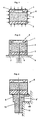
- Fig. 1 in geschnittener Ansicht ein erfindungsgemäss aufgebautes Wandlerelement mit Darstellung der vom Messdruck ausgeübten Kräfte.
- Fig. 2 fragmentarische Teilansichten von Wandlerelementen ählich Fig. 1 für Absolutdruckmessungen (linke Zeichnungshälfte) bzw. Relativdruckmessungen (rechte Zeichnungshälfte) und deren Befestigung auf entsprechend ausgebildeten Montageplatten bzw. Halterungen und mit eingezeichneten Verformungskräften.
- Fig. 3 fragmentarische Teilansichten von Wandlerelementen ähnliche Fig. 2 für Absolut- bzw. Relativdruckmessungen in Verbindung mit entspechend ausgebildeten Zwischenträgern, wobei die Basisplatte wesentlich stärker als die Membranplatte ausgebildet ist,
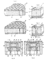
- Fig. 4 eine perspektivische geschnittene Teilansicht eines Laminates aus einem Membranwafer und einem isolierenden Substrat,
- Fig. 5 eine perspektivische geschnittene Ansicht eines aus dem Laminat nach Fig. 4 geschnittenen Wandlerelementes mit nachträglich befestigter Basisplatte,
- Fig. 6 eine perspektivische geschnittene Teilansicht eines Laminates, bestehend aus einem Membranwafer, einem Basiswafer und einem dazwischen angeordneten Substrat,
- Fig. 7 eine perspektivische geschnittene Ansicht eines aus dem Laminat nach Fig. 6 geschnittenen Wandlerelementes für Relativdruckmessungen,
- Fig. 8 eine geschnittene Ansicht von einem erfindungsgemässen Druckaufnehmer gemäss einer ersten Ausführungsform mit einer Wandlerelement nach der Erfindung, und
- Fig. 9
bis 11 geschnittene Ansichten von bevorzugten Ausführungsformen von erfindungsgemässen Druckaufnehmern mit Wandlerelementen nach der Erfindung.
- 1 is a sectional view of a transducer element constructed according to the invention, showing the forces exerted by the measuring pressure.
- Fig. 2 fragmentary partial views of transducer elements similar to Fig. 1 for absolute pressure measurements (left half of the drawing) or relative pressure measurements (right half of the drawing) and their attachment to appropriately designed mounting plates or brackets and with drawn deformation forces.
- 3 fragmentary partial views of transducer elements similar to FIG. 2 for absolute or relative pressure measurements in connection with appropriately designed intermediate supports, the base plate being designed much stronger than the membrane plate,
- 4 is a partial perspective sectional view of a laminate made of a membrane wafer and an insulating substrate,
- 5 is a perspective sectional view of a transducer element cut from the laminate according to FIG. 4 with a base plate subsequently attached,
- 6 is a partial perspective sectional view of a laminate consisting of a membrane wafer, a base wafer and a substrate arranged between them,
- 7 is a perspective sectional view of a transducer element cut from the laminate according to FIG. 6 for relative pressure measurements,
- 8 shows a sectional view of a pressure transducer according to the invention according to a first embodiment with a transducer element according to the invention, and
- 9 to 11 are sectional views of preferred embodiments of pressure transducers according to the invention with transducer elements according to the invention.
In der Zeichnung tragen gleiche oder ähnliche Teile die gleichen Bezugszeichen. Die verwendeten Begriffe "oben" und "unten" beziehen sich auf die in der Zeichnung wiedergegebene Lage der Teile.In the drawing, the same or similar parts have the same reference numerals. The terms "above" and "below" refer to the position of the parts shown in the drawing.
In Fig. 1 ist mit dem allgemeinen Bezugszeichen 8 ein kräftesymmetrisches bzw. dehungskompensiertes Wandlerelement nach der Erfindung gezeigt, das eine obere Membranplatte 1, eine zwischenliegende isolierende Platte 2 und eine untere Basisplatte 3 umfasst. Die Membranplatte 1 besteht aus einem Halbleitermaterial, vorzugsweise Silizium, in dessen mittleren Bereich von unten eine Aussparung 4 eingebracht ist, die die Wandstärke der Platte 1 membranartig verdünnt. Die Membranplatte 1 weist Piezowiderstände auf, die nach bekannten Methoden der Halbleitertechnik in die Platte eindiffundiert oder auf ihr befestigt sein können.In Fig. 1, the
Mit ihrem dickwandigen Randbereich ist die Membranplatte 1 auf der isolierenden Platte 2 befestigt. Die isolierende Platte 2 sollte aus einem Material mit geeignetem Temperaturausdehnungskoeffizienten in Bezug auf die Membranplatte 1 bestehen, das sich zudem gut mit der Membranplatte 1 verbinden lässt. Geeignet für die isolierende Platte 2 sind insbesondere Glasmaterialien, vorzugsweise Borsilikat-Gläser, deren thermischer Ausdehnungskoeffizient zwar niedriger ist als derjenige anderer Gläser, aber immer noch höher als derjenige von Silizium ist.The
Die Basisplatte 3 kann grundsätzlich aus irgendeinem geeigneten Material bestehen, das einen ebenso niedrigen oder niedrigeren Temperaturausdehnungskoeffizienten wie das Material der Membranplatte 1 hat. Silizium hat sich als geeignet für die Basisplatte 3 erwiesen.The
Die Verbindung der Platten 1, und 3 kann nach bekannten Methoden der Halbleitertechnik erfolgen, wobei insbesondere die anodische-Verbindung wegen ihrer hohen Festigkeit und Steifigkeit bevorzugt wird. Die anodische Verbindungstechnik ist dem Fachmann bekannt und braucht deshalb nicht näher erläutert zu werden.The
In einer bevorzugten Ausführung der Erfindung ist die Basisplatte 3 so auf die Membranplatte 1 abgestimmt, dass bei Temperaturänderungen die im Wandlerelement auftretenden Kräfte ungefähr symmetrisch wirken, wie etwa in Fig. 2 angedeutet. Dies bedeutet, dass insbesondere die Flächenausdehnungskräfte, die zwischen der Membranplatte 1 und der isolierenden Platte 2 einerseits bzw. zwischen der Basisplatte 3 und der isolierenden Platte 2 andererseits wirken, im wesentlichen gleich sind und wegen der gleichmässigen Schubspannungsverteilung auf beiden Seiten der Glasplatte die niedrigesten Spannungsspitzen auftreten. Ausserdem treten keine Verwerfungen des Wandlerelementes, insbesondere von dessen Membranplatte, auf. Dies wird durch die erwähnte Wahl der für die Membranplatte 1 und die Basisplatte 3 verwendeten Materialien mit im wesentlichen gleichen Temperaturausdehnungskoeffizienten erreicht und ferner dadurch, dass die Konfiguration bzw. Abmessung, d.h. insbesondere die Dicke, der Basisplatte 3 auf die Membranplatte 1 abgestimmt ist, so dass die in den beiden Platten 1 und 3 auftretenden Flächenausdehnungskräfte einander im wesentlichen kompensieren. Im Ergebnis wird ein Wandlerelement erhalten, das sich bei Temperaturänderung nicht oder nur unwesentlich verformt, d.h. seine ursprüngliche Gestalt beibehält.
- Fig. 2 zeigt auf der linken Zeichnungshälfte
ein Wandlerelement 8 gemäss Fig. 1 für Absolutdruckmessungen, während das auf der rechten Zeichnungshälfte von Fig. 2 dargestellte Wandlerelement für Relativdruckmessungen ausgebildet ist. Zu diesem Zweck sind dieBasisplatte 3 und dieisolierende Platte 2 von einer Durchgangsbohrung 6 durchsetzt, die in der Aussparung 4der Membranplatte 1 ausmündet. Die Aussparung 4 und damit die Unterseite des Membranbereiches der Membranplatte 1 können daher unter Druck gesetzt werden. Die Bohrung kann in irgendeiner geeigneten Weise, z.B. durch Ultraschall, in das Wandlerelement eingebracht werden. - Fig. 2 zeigt weiter,
wie das Wandlerelement 8 an einer Unterlage bzw.Halterung 7durch eine Zwischenschicht 5 befestigt ist. Ein bevorzugtes Verfahren zum Befestigen des Wandlerelementes 8 auf der Haltung 7 ist das sog. Glasfritten, bei dem auf die zu verbindenen Oberflächen Glaspulver aufgestreut und aufgeschmolzen wird. Diese Technik ist dem Fachmann bekannt und braucht nicht näher erläutert zu werden. Eine einfachere Methode ist das Aufkleben. - Fig. 3 zeigt ein Wandlerelement für Absolutdruckmessungen bzw. Relativdruckmessungen (linke bzw. rechte Zeichungshälfte), bei
dem die Basisplatte 3 verdickt und auf einem im Querschnitt T-förmigen oder pilzförmigen metallischen Zwischenträger 9, 9' in geeigneter Weise z.B. mittels eines Epoxyklebers, durch Glasfritten oder Löten befestigt ist.Der Zwischenträger 9, 9' besteht vorzugsweise aus einem Material, das sich unter Temperaturänderung ähnlich wie das material der isolierendenPlatte 2 verhält. Aber selbst bei deutlich unterschiedlichen Temperaturausdehnungskoeffizienten der Materialien fürden Zwischenträger 9 und dieisolierende Platte 2 wirkt dieBasisplatte 3 des Wandlerelementes ausgleichend dergestalt, dass eine Rissbildung der isolierendenPlatte 2 vermieden wird. Diese Gefahr besteht, wenndie isolierende Platte 2 direkt. aufdem metallischen Zwischenträger 9, 9' befestigt werden würde, da alle Glassorten nur sehr geringe Zugspannungen zulassen.
- Fig. 2 shows on the left cartoon wind h voltage half a
transducer element 8 according to FIG. 1 for absolute pressure measurements, while formed on the right half of the drawing of Fig. 2 shown transducer element for pressure measurements. For this purpose, thebase plate 3 and the insulatingplate 2 are penetrated by a through hole 6, which opens into the recess 4 of themembrane plate 1. The recess 4 and thus the underside of the membrane area of themembrane plate 1 can therefore be put under pressure. The bore can be made in the transducer element in any suitable manner, for example by ultrasound. - 2 further shows how the
transducer element 8 is fastened to a base orholder 7 by means of anintermediate layer 5. A preferred method for attaching thetransducer element 8 to theholder 7 is the so-called glass frit, in which glass powder is sprinkled and melted onto the surfaces to be connected. This technique is known to the person skilled in the art and need not be explained in more detail. A simpler method is to stick it on. - Fig. 3 shows a transducer element for absolute pressure measurements or relative pressure measurements (left or right half of the drawing), in which the
base plate 3 is thickened and on a cross-sectionally T-shaped or mushroom-shaped metallicintermediate carrier 9, 9 'in a suitable manner, for example by means of an epoxy adhesive Glass frit or soldering is attached. Theintermediate carrier 9, 9 'preferably consists of a material which behaves similarly to the material of the insulatingplate 2 with a change in temperature. But even with significantly different coefficients of thermal expansion of the materials for theintermediate carrier 9 and the insulatingplate 2, thebase plate 3 of the transducer element has a compensating effect such that cracking of the insulatingplate 2 is avoided. This danger exists if the insulatingplate 2 is directly. would be attached to the metallicintermediate support 9, 9 ', since all types of glass only allow very low tensile stresses.
Wie gezeigt kann er von Vorteil sein, die Basisplatte 3 dicker als die Membranplatte 1 auszuführen. Für gewisse Temperaturbereiche lassen sich durch unsymmetrische Kräfteverteilung geringere Spannungsspitzen in der Membranplatte 1 erreichen.As shown, it can be advantageous to make the
Der Zwischenträger 9,9', der in Verbindung mit einem Wandlerelement für Relativdruckmessungen ebenfalls von einer zu der Bohrung 6 ausgerichteten Durchgangsbohrung durchsetzt ist, kann an seinem Schaftbereich 10 eine lötfähige Oberflächenschicht 11 aufweisen. Dies eröffnet z.B. die Möglichkeit, im sog. Batchverfahren gleichzeitig eine Vielzahl von Zwischenträgern 9, 9' mit daran befestigten Wandlerelementen 8 an einer entsprechenden Vielzahl von Halterungen 7 anzulöten.The
Anhand von Fig. 4, 5, 6 und 7 werden nachfolgend bevorzugte Verfahren zum Herstellen der Wandlerelemente nach der Erfindung beschrieben. Dabei wird grundsätzlich von Methoden der Halbleitertechnik Gebrauch gemacht, wie sie z.B. in der US-PS-37 64 950 beschrieben sind.4, 5, 6 and 7, preferred methods for producing the transducer elements according to the invention are described below. Basically, methods of Semiconductor technology made use of, as described, for example, in US Pat. No. 3,764,950.
Nach Fig. 4 wird auf einem isolierenden plattenförmigen Substrat 17, aus z.B. einem geeigneten Glasmaterial, ein sog. Wafer 18 aus einem für die Bildung der Membranplatten 1 geeigneten Halbleitermaterial, wie Silizium, mittels einer anodischen Verbindung 16 aufgebracht. Der Wafer ist, wie dargestellt, in eine Vielzahl von Einheiten unterteilt, die eine Abmessung und Konfiguration entsprechend der Membranplatte 1 eines herzustellenden Wandlerelementes haben.According to Fig. 4 is on an insulating plate-shaped
Für die Schaffung von Wandlerelementen für Relativdruckmessungen kann das plattenförmige Substrat 17, wie bei 15 angedeutet, durchbohrt sein.For the creation of converter elements for relative pressure measurements, the plate-shaped
Das Zweischichtenlaminat nach Fig. 4 hat den Vorteil, dass die Verbundungszone 16 zwischen dem Wafer 18 und dem isolierenden Substrat 17, das vorzugsweise eine Glasplatte ist, leicht optisch überwacht werden kann. Man erkennt dabei sofort die Zonen, die eine perfekte Verbindung der beiden Platten eingegangen sind. Aus dem Zweischichtenlaminat gemäss Fig. 4 werden Einheiten entsprechend jeweils einem Wandlerelement mit einer Membranplatte 1 und einer isolierenden Platte 2 gemäss Fig. 5 z.B. mittels einer Diamantsäge geschnitten. Auf jede so gebildete Einheit wird anschliessend eine vorgefertigte Basisplatte 3, wie sie in Verbindung mit Fig. 1 beschrieben wurde, z.B. durch eine Glasfrittenverbindung 14, befestigt.The two-layer laminate according to FIG. 4 has the advantage that the
Es besteht auch die Möglichkeit, die Basisplatte 3 in ein und demselben Wärmebehandlungsvorgang gleichzeitig an der isolierenden Platte 2 und an der Halterung 7 des Aufnehmers zu befestigen, wie dies in Fig. 5 durch die Zwischenschicht 5 angedeutet ist, bei der es sich ebenfalls um eine Glasfrittenverbindung handeln kann. Mit dem Bezugszeichen 19 sind Anschlussstellen an der Membranplatte 1 angedeutet, über die das elektrische Signal der Widerstände abgenommen werden kann.There is also the possibility of simultaneously fixing the
Das in Fig. 6 gezeigte Verfahren unterscheidet sich von dem Verfahren nach Fig. 5 darin, dass auf der dem Wafer 18 gegenüberliegenden Seite des isolierenden Substrates 17 ein weiterer Wafer 20 aufgebracht ist, aus dem die Basisplatten 3 gebildet werden. Die Wafer 18 und 20 sind mit dem isolierenden Substrat 17 vorzugsweise durch anodische Verbindungen 16 verbunden. Ein aus dem Dreischichtenlaminat gemäss Fig. 6 herausgeschnittenes Wandlerelement ist in Fig. 7 gezeigt und entspricht dem Element, das in Verbindung mit Fig. 1 und 2 näher erläutert wurde. Das Wandlerelement kann über eine Zwischenschicht 5, z.B. eine Glasfrittenverbindung, auf der Halterung 7 des Aufnehmers befestigt sein, oder es kann auch eine Klebung vorgesehen werden.The method shown in FIG. 6 differs from the method according to FIG. 5 in that a
Fig. 8 zeigt einen Druckaufnehmer mit einem symmetrischen Wandlerelement 8 gemäss Fig. 1. Das Wandlerelement 8 ist über eine Zwischenschicht 5 direkt auf der plattenförmigen Halterung des Aufnehmers befestigt bzw. aufgeklebt. Die Halterung 7 weist Bohrungen auf, in denen elektrische Leiter 22 in Glasaugen 26 eingegossen sind. Die elektrischen Leiter 22 sind mit den Anschlussstellen 19 der Widerstände an der Membranplatte 1 durch Drähte 27 aus Gold oder Aluminium verbunden.FIG. 8 shows a pressure sensor with a
Die Halterung 7 liegt, wie dargestellt, auf einer ringförmigen Absatzfläche an einer zwischenliegenden Stelle des Aufnehmergehäuses 32 auf und ist durch eine umfängliche Schweissnaht 24 hermetisch mit dem Aufnehmergehäuse verbunden. Die Druckbeaufschlagung des Wandlerelementes 8 erfolgt über ein Druckübertragungsmedium 25, bei dem es sich vorzugsweise um Silikonöl handelt. Das Druckübertragungsmedium füllt im wesentlichen den vom Gehäuse 32 oberhalb der Halterung 7 umschlossenen Raum der, wie dargestellt, oben durch eine am Gehäuse 32 befestigte elastische Metallmembran 28 abgedichtet ist. Um das Volumen des Raumes bzw. die Menge an eingefülltem Druckübertragungsmedium 25 klein zu halten, ist in dem Gehäuse ein Ring 21 aus einem keramischen Material eingesetzt. Die Halterung 7 besteht wegen der besseren Bearbeitungsmöglichkeit und der erforderlichen Durchführungsbohrungen für die Leiter 22 aus einem nicht korrosionsfestem Stahl mit einem Temperaturausdehnungskoeffizienten, der kleiner als der Ausdehnungskoeffizient der für das Gehäuse der Druckaufnehmer vorzugsweise verwendeten austenitischen Stähle ist. Bei Temperaturänderung können daher wegen der unterschiedlichen Ausdehnungskoeffizienten zwischen der Halterung und dem Gehäuse der Druckaufnehmer Verwerfungen auftreten, die sich ebenfalls nachteilig auf die Messgenauigkeit und Reproduzierbarkeit auswirken. Um dies zu verhindern, ist bei den in Fig. 9-11 gezeigten bevorzugten Druckaufnehmern nach der Erfindung die das Wandlerelement tragende Halterung über ein rohrförmiges elastisches Teil 30 mit dem Aufnehmergehäuse 33 verbunden.As shown, the
Diese dehnungselastische Anbindung bewirkt, dass sich Wärmespannungen wesentlich geringer auf die Zwischenschicht zwischen Halterung und Wandlerelement auswirken, als dies bei der einfachen plattenförmigen Halterung gemäss der Ausführungsform nach Fig. 8 der Fall ist. Die dehnungselastische Anbindung liefert daher einen weiteren wichtigen Beitrag hinsichtlich der Schaffung von piezoresistiven Druckaufnehmern für Präzisionsmessungen, bei denen die Messgenauigkeit durch Temperaturänderungen im wesentlichen nicht beeinträchtigt wird.This stretch-elastic connection has the effect that thermal stresses have a significantly lower effect on the intermediate layer between the holder and the transducer element than is the case with the simple plate-shaped holder according to the embodiment according to FIG. 8. The elastic connection therefore makes another important contribution to the creation of piezoresistive pressure transducers for precision measurements, in which the measuring accuracy is essentially not affected by temperature changes.
Bei dem Druckaufnehmer gemäss Fig. 9 ist das rohrförmige dehnungselastische Teil 30 an der gleichen Seite wie das Wandlerelement 8 an der Halterung 7 angeformt und an seiner freien oberen Stirnseite, wie bei 31 angedeutet, über eine Stumpfverschweissung mit einer horizontalen Absatzfläche am Aufnehmergehäuse 33 verschweisst. Ansonsten entspricht der Aufnehmer nach Fig. 9 dem nach Fig. 8, so dass insofern hierauf Bezug genommen werden kann. Der Aufnehmer nach Fig. 9 hat den Vorteil, dass die Anordnung aus Halterung 7 und Wandlerelement 8 von unten in das Gehäuse 33 eingesetzt werden kann, nachdem die Membran 28 an Gehäuse befestigt worden ist. Die ordnungsgemässe Befestigung und Ausbildung der Membran 28 kann daher überprüft werden, bevor die Halterung 7 mit dem Wandlerelement 8 über das rohrförmige Teil 30 am Gehäuse 33 befestigt wird.In the pressure transducer according to FIG. 9, the tubular,
Fig. 10 zeigt einen Druckaufnehmer mit einer Halterung 7, die an ihrer oberen Seite eine Aussparung aufweist, in der das Wandlerelement 8 z.B. durch eine Schicht 40 auf Basis eines Epoxyharzes befestigt ist. Von der dem Wandlerelement 8 abgewandten unteren Seite der Halterung 7 steht das rohrförmige dehnungselastische Teil 30 ab, das an seiner freien Stirnseite mit einer Absatzfläche am Aufnehmergehäuse 39 stumpfverschweisst ist. Da sich das rohrförmige Teil 30 von der Membran 28 wegersteckt, muss die Anordnung aus der Halterung 7 mit dem daran befestigten Wandlerelement 8 zunächst am Gehäuse 39 befestigt werden, bevor die Membran 28 montiert werden kann. Infolge der Montage von der Membranseite her eröffnet sich die Möglichkeit, das Druckübertragungsmedium 25 auch in einem ringförmigen Raum 38 zwischen der Halterung und der inneren Umfangsfläche des Gehäuses 39 und damit radial auf die Halterung 7 wirken zu lassen. Die elektrischen Leiter 22 werden daher auch unter hohen Mediumdrücken nicht undicht oder aus den Glasaugen 26 herausgepresst. Der in Fig. 10 gezeigte Druckaufnehmer eignet sich daher insbesondere für Hochdruckmessungen.Fig. 10 shows a pressure sensor with a
Wie dargestellt, kann weiter eine Platte 33 mit Kompensationswiderständen 34 an einem unteren Bereich des Aufnehmergehäuses 39 befestigt sein. Die elektrischen Leiter 22 sind über Gleitbüchsen 37 durch die Platte 33 geführt.As shown, a
Litzen 36 der elektrischen Leiter 22 dienen der Signalabführung. Die Platte 33, die Widerstände 34 und die elektrischen Leiter 22 können in einer Kunststoffmasse 35 eingebettet sein, die im unteren Bereich des Gehäuses 39 wie dargestellt, eingeführt ist.
Fig. 11 zeigt einen Druckaufnehmer für Relativdruckmessungen unter Verwendung einer Anordnung aus Wandlerelement und Zwischenträger, wie sie in Fig. 3 auf der rechten Zeichnungshälfte gezeigt ist. Das symmetrische Wandlerelement 8 ist, wie in Verbindung mit Fig. 3 beschrieben, an dem T-förmigen Zwischenträger befestigt, der seinerseits mit seinem Schaftbereich 10 in einem Loch in der Halterung 7 eingelötet ist. Statt der Lötverbindung kann auch eine Kittverbindung vorgesehen werden.FIG. 11 shows a pressure transducer for relative pressure measurements using an arrangement of transducer element and intermediate carrier, as shown in FIG. 3 on the right half of the drawing. As described in connection with FIG. 3, the
Wie bei der Ausführung nach Fig. 9 wird die Halterung 7 mit dem elastischen rohrförmigen Teil 30 und der angelöteten Anordnung aus Zwischenträger und Wandlerelement von unten in das Aufnehmergehäuse 53 eingesetzt, wonach die freie obere Stirnseite des rohrförmigen Teiles 30 mit einer ringförmigen Absatzfläche am Aufnehmergehäuse 53, wie bei 31 angedeutet, stumpfverschweisst wird. Die für die Relativdruckmessung erforderliche Druckzuführung zu der Unterseite der Membranplatte des Wandlerelementes 8 erfolgt über ein am Schaftbereich 10 des Zwischenträgers befestigtes Rohr 50, das sich nach unten aus dem Aufnehmer herauserstreckt. Die Länge L des rohrförmigen elastischen Teiles 30 kann entsprechend den jeweiligen Verhältnissen gewählt werden, so dass stets gewährleistet ist, dass die die elektrischen Leiter 22 haltenden Glasaugen 26 nicht durch die Schweissung an der Stelle 31 überhitzt werden und gleichzeitig das rohrförmige elastische Teil 30 die gewünschte dehnungsausgleichende Wirkung ausüben kann. Ansonsten entspricht der in Fig. 11 gezeigte Aufnehmer im wesentlichen der Ausführung nach Fig. 9 und in Bezug auf die im unteren Teil des Aufnehmergehäuses vorgesehenen Teile den Teilen 33 bis 37 bei der Ausführungsform nach Fig. 10, so dass hierauf Bezug genommen werden kann.As in the embodiment according to FIG. 9, the
Gemeinsam ist den in Fig. 9 bis 11 gezeigten Druckaufnehmern, dass sie infolge der Kombination eines symmetrischen und damit verwerfungsfreien Wandlerelementes mit einer verspannungsfreien Verbindung der Halterungen mit den Aufnehmergehäusen über ein rohrförmiges dehnungselastisches Teil eine aussergewöhnliche Stabilität und Nullpunktkonstanz aufweisen und damit Präzisionsdruckaufnehmer darstellen. Diese Druckaufnehmer können dank der hochentwickelten Halbleitertechnik in Verbindung mit den bekannten Batchverfahren dennoch preiswert hergestellt werden.Common to the pressure transducers shown in Figs. 9 to 11 is that, due to the combination of a symmetrical and therefore distortion-free transducer element with a tension-free connection of the brackets to the transducer housings via a tubular, elastic part, they have exceptional stability and zero point constancy and thus represent precision pressure transducers. Thanks to the highly developed semiconductor technology in conjunction with the known batch processes, these pressure transducers can still be manufactured inexpensively.
Claims (18)
Priority Applications (5)
| Application Number | Priority Date | Filing Date | Title |
|---|---|---|---|
| DE8383111227T DE3376760D1 (en) | 1983-11-10 | 1983-11-10 | Transducer element, method for its manufacture and its use in a pressure pick-up device |
| AT83111227T ATE34613T1 (en) | 1983-11-10 | 1983-11-10 | TRANSDUCER ELEMENT, PROCESS FOR ITS MANUFACTURE AND USE FOR A PRESSURE TRANSDUCER. |
| EP83111227A EP0140992B1 (en) | 1983-11-10 | 1983-11-10 | Transducer element, method for its manufacture and its use in a pressure pick-up device |
| US06/645,262 US4675643A (en) | 1983-11-10 | 1984-08-29 | Pressure transducer utilizing a transduction element |
| JP59237407A JPS60167385A (en) | 1983-11-10 | 1984-11-10 | Transducer element, method of producing same and pressure transducer associated with transducer element |
Applications Claiming Priority (1)
| Application Number | Priority Date | Filing Date | Title |
|---|---|---|---|
| EP83111227A EP0140992B1 (en) | 1983-11-10 | 1983-11-10 | Transducer element, method for its manufacture and its use in a pressure pick-up device |
Publications (2)
| Publication Number | Publication Date |
|---|---|
| EP0140992A1 EP0140992A1 (en) | 1985-05-15 |
| EP0140992B1 true EP0140992B1 (en) | 1988-05-25 |
Family
ID=8190798
Family Applications (1)
| Application Number | Title | Priority Date | Filing Date |
|---|---|---|---|
| EP83111227A Expired EP0140992B1 (en) | 1983-11-10 | 1983-11-10 | Transducer element, method for its manufacture and its use in a pressure pick-up device |
Country Status (5)
| Country | Link |
|---|---|
| US (1) | US4675643A (en) |
| EP (1) | EP0140992B1 (en) |
| JP (1) | JPS60167385A (en) |
| AT (1) | ATE34613T1 (en) |
| DE (1) | DE3376760D1 (en) |
Families Citing this family (36)
| Publication number | Priority date | Publication date | Assignee | Title |
|---|---|---|---|---|
| DE3569824D1 (en) * | 1985-09-11 | 1989-06-01 | Kunz Manfred | Pressure sensor |
| DE3772514D1 (en) * | 1986-10-28 | 1991-10-02 | Sumitomo Electric Industries | MEASURING METHOD FOR A SEMICONDUCTOR PRESSURE SENSOR. |
| DE3777188D1 (en) * | 1987-11-27 | 1992-04-09 | Kristal Instr Ag | MEASURING CELL, ESPECIALLY FOR RELATIVE AND DIFFERENTIAL PRESSURE MEASUREMENTS. |
| US5000047A (en) * | 1988-03-29 | 1991-03-19 | Nippondenso Co., Ltd. | Pressure sensor |
| US4926155A (en) * | 1988-12-12 | 1990-05-15 | Johnson Service Company | Integrated circuit silicon pressure transducer package |
| US4930929A (en) * | 1989-09-26 | 1990-06-05 | Honeywell Inc. | Glass tube/stainless steel header interface for pressure sensor |
| KR930011091B1 (en) * | 1990-06-08 | 1993-11-20 | 미쯔비시 덴끼 가부시끼가이샤 | Pressure sensor |
| US5421956A (en) * | 1991-11-20 | 1995-06-06 | Nippondenso Co., Ltd. | Method of fabricating an integrated pressure sensor |
| US5333505A (en) * | 1992-01-13 | 1994-08-02 | Mitsubishi Denki Kabushiki Kaisha | Semiconductor pressure sensor for use at high temperature and pressure and method of manufacturing same |
| DE4211816C2 (en) * | 1992-04-08 | 1995-08-31 | Danfoss As | Pressure sensor |
| DE4321804A1 (en) * | 1993-06-30 | 1995-01-12 | Ranco Inc | Process for the production of small components |
| US5703296A (en) * | 1995-06-27 | 1997-12-30 | Delco Electronics Corp. | Pressure sensor having reduced hysteresis and enhanced electrical performance at low pressures |
| DE19612964A1 (en) * | 1996-04-01 | 1997-10-02 | Bosch Gmbh Robert | Pressure sensor and method for manufacturing a pressure sensor |
| KR100432068B1 (en) * | 1996-04-13 | 2004-09-08 | 로베르트 보쉬 게엠베하 | Pressure sensor |
| JPH1130559A (en) | 1997-07-10 | 1999-02-02 | Fuji Koki Corp | Pressure sensor |
| US6076409A (en) * | 1997-12-22 | 2000-06-20 | Rosemount Aerospace, Inc. | Media compatible packages for pressure sensing devices |
| US6311561B1 (en) | 1997-12-22 | 2001-11-06 | Rosemount Aerospace Inc. | Media compatible pressure sensor |
| US6570485B1 (en) * | 2000-11-17 | 2003-05-27 | Honeywell International Inc. | Transducer packaging assembly for use in sensing unit subjected to high G forces |
| US7641864B2 (en) * | 2001-06-15 | 2010-01-05 | Avure Technologies Incorporated | Thermal sensor connector for pressure vessel |
| EP1570247B1 (en) * | 2002-12-12 | 2012-10-24 | Danfoss A/S | A pressure sensor |
| JP2004198147A (en) * | 2002-12-16 | 2004-07-15 | Toyoda Mach Works Ltd | Pressure sensor |
| US6883380B2 (en) * | 2003-05-16 | 2005-04-26 | Rosemount Inc | Pressure sensor capsule |
| JP2005037310A (en) * | 2003-07-18 | 2005-02-10 | Fuji Koki Corp | Pressure sensor |
| US20060255669A1 (en) * | 2005-05-12 | 2006-11-16 | Remy International, Inc. | Flexible diode connection for pressfit bridge rectifier |
| US7458275B2 (en) | 2007-03-15 | 2008-12-02 | Rosemount Inc. | Welded header for pressure transmitter |
| CN101960276B (en) * | 2007-10-30 | 2013-07-03 | 阿自倍尔株式会社 | Pressure sensor and method for manufacturing the same |
| DE102008049143B4 (en) * | 2008-09-26 | 2012-08-16 | Intelligente Sensorsysteme Dresden Gmbh | Pressure sensor and manufacturing process |
| US8371175B2 (en) * | 2009-10-01 | 2013-02-12 | Rosemount Inc. | Pressure transmitter with pressure sensor mount |
| TWI633289B (en) * | 2013-03-13 | 2018-08-21 | 不二工機股份有限公司 | Pressure sensor |
| DE102014119396A1 (en) * | 2014-12-22 | 2016-06-23 | Endress + Hauser Gmbh + Co. Kg | Pressure measuring device |
| EP3124943B1 (en) | 2015-07-31 | 2021-06-02 | Kistler Holding AG | Piezoelectric pressure sensor and method for producing said piezoelectric pressure sensor |
| DK3124945T3 (en) | 2015-07-31 | 2018-10-22 | Kistler Holding Ag | PIEZOELECTRIC PRESSURE SENSOR |
| EP3124938B1 (en) | 2015-07-31 | 2019-02-20 | Kistler Holding AG | Pressure sensor |
| EP3124947B1 (en) | 2015-07-31 | 2018-12-05 | Kistler Holding AG | Pressure sensor |
| JP6835028B2 (en) * | 2018-03-30 | 2021-02-24 | 横河電機株式会社 | Airtight terminal and sensor unit |
| DE102018130917A1 (en) | 2018-12-05 | 2020-06-10 | Danfoss A/S | Sensor arrangement |
Citations (1)
| Publication number | Priority date | Publication date | Assignee | Title |
|---|---|---|---|---|
| US3764950A (en) * | 1972-07-17 | 1973-10-09 | Fairchild Camera Instr Co | Methods for making semiconductor pressure transducers and the resulting structures |
Family Cites Families (8)
| Publication number | Priority date | Publication date | Assignee | Title |
|---|---|---|---|---|
| DE33749C (en) * | J. DAX in Köln a. Rhein, Alte Mauer am Bach Nr. 22 | Zinc torch | ||
| NL7415668A (en) * | 1974-12-02 | 1976-06-04 | Philips Nv | PRESSURE TRANSMITTER. |
| JPS5524423A (en) * | 1978-08-10 | 1980-02-21 | Nissan Motor Co Ltd | Semiconductor pressure sensor |
| JPS5543819A (en) * | 1978-09-22 | 1980-03-27 | Hitachi Ltd | Pressure detecting equipment |
| ATE7737T1 (en) * | 1980-02-06 | 1984-06-15 | Hans W. Dipl.-Phys. Keller | PIEZORESISTIVE CYLINDER CAN LIKE PRESSURE GAUGE. |
| DE3009163A1 (en) * | 1980-03-10 | 1981-09-24 | Siemens AG, 1000 Berlin und 8000 München | Piezo-resistive pressure sensor with semiconductor membrane - is provided with precious metal layer on periphery before soldering to carrier |
| JPS5723830A (en) * | 1980-07-18 | 1982-02-08 | Hitachi Ltd | Post material for pressure transducer of semiconductor and its preparation |
| US4527428A (en) * | 1982-12-30 | 1985-07-09 | Hitachi, Ltd. | Semiconductor pressure transducer |
-
1983
- 1983-11-10 AT AT83111227T patent/ATE34613T1/en not_active IP Right Cessation
- 1983-11-10 DE DE8383111227T patent/DE3376760D1/en not_active Expired
- 1983-11-10 EP EP83111227A patent/EP0140992B1/en not_active Expired
-
1984
- 1984-08-29 US US06/645,262 patent/US4675643A/en not_active Expired - Fee Related
- 1984-11-10 JP JP59237407A patent/JPS60167385A/en active Pending
Patent Citations (1)
| Publication number | Priority date | Publication date | Assignee | Title |
|---|---|---|---|---|
| US3764950A (en) * | 1972-07-17 | 1973-10-09 | Fairchild Camera Instr Co | Methods for making semiconductor pressure transducers and the resulting structures |
Also Published As
| Publication number | Publication date |
|---|---|
| EP0140992A1 (en) | 1985-05-15 |
| US4675643A (en) | 1987-06-23 |
| ATE34613T1 (en) | 1988-06-15 |
| JPS60167385A (en) | 1985-08-30 |
| DE3376760D1 (en) | 1988-06-30 |
Similar Documents
| Publication | Publication Date | Title |
|---|---|---|
| EP0140992B1 (en) | Transducer element, method for its manufacture and its use in a pressure pick-up device | |
| DE4203832C2 (en) | Semiconductor pressure transducer | |
| EP0351701B1 (en) | Pressure transducer and its manufacturing process | |
| DE19714703B4 (en) | pressure sensor | |
| DE3047276C2 (en) | Differential pressure meter | |
| DE2938240A1 (en) | PRESSURE-SENSITIVE DEVICE AND METHOD FOR THEIR PRODUCTION | |
| DE10305625B4 (en) | pressure sensor | |
| DE69910464T2 (en) | Process for connecting different elements | |
| EP0189492B1 (en) | Method for manufacturing a measuring transducer for measuring mechanical quantities | |
| DE8407322U1 (en) | PIEZORESESTIVE PRESSURE MEASURING CELL | |
| DE2820478A1 (en) | CAPACITIVE PRESSURE SENSOR CONVERTER AND METHOD FOR ITS MANUFACTURING | |
| DE3128188C2 (en) | Pressure sensor in semiconductor design | |
| DE3937522A1 (en) | SEMICONDUCTOR PRESSURE SENSOR CONNECTED TO A CARRIER ELEMENT | |
| DE3913031A1 (en) | PRESSURE SENSOR | |
| DE2617731C3 (en) | Miniature pressure transducer | |
| DE3025996C2 (en) | Method for manufacturing a displacement transducer | |
| DE19531058A1 (en) | Semiconductor acceleration sensor for e.g. pressure sensor with integrated computer chip | |
| WO2010108949A1 (en) | Pressure sensor | |
| DE10134586A1 (en) | Sensor device for detecting an expansion stress | |
| DE102006023724B4 (en) | Measuring cell arrangement for a pressure sensor with force measuring element made of glass | |
| DE3041229A1 (en) | PRESSURE SOCKET AND METHOD FOR THEIR PRODUCTION | |
| DE102016112200A1 (en) | Pressure transducer | |
| EP0317664A1 (en) | Measurement cell, particularly for measurements of relative and differential pressure | |
| DE3033028A1 (en) | PRECISION RESISTOR AND METHOD FOR THE PRODUCTION THEREOF. | |
| EP0147614B1 (en) | Pressure detector with a sensor quartz |
Legal Events
| Date | Code | Title | Description |
|---|---|---|---|
| PUAI | Public reference made under article 153(3) epc to a published international application that has entered the european phase |
Free format text: ORIGINAL CODE: 0009012 |
|
| AK | Designated contracting states |
Designated state(s): AT CH DE FR GB LI |
|
| 17P | Request for examination filed |
Effective date: 19850608 |
|
| RAP1 | Party data changed (applicant data changed or rights of an application transferred) |
Owner name: KRISTAL INSTRUMENTE AG |
|
| 17Q | First examination report despatched |
Effective date: 19860711 |
|
| R17C | First examination report despatched (corrected) |
Effective date: 19870303 |
|
| GRAA | (expected) grant |
Free format text: ORIGINAL CODE: 0009210 |
|
| AK | Designated contracting states |
Kind code of ref document: B1 Designated state(s): AT CH DE FR GB LI |
|
| PG25 | Lapsed in a contracting state [announced via postgrant information from national office to epo] |
Ref country code: FR Free format text: THE PATENT HAS BEEN ANNULLED BY A DECISION OF A NATIONAL AUTHORITY Effective date: 19880525 |
|
| REF | Corresponds to: |
Ref document number: 34613 Country of ref document: AT Date of ref document: 19880615 Kind code of ref document: T |
|
| GBT | Gb: translation of ep patent filed (gb section 77(6)(a)/1977) | ||
| REF | Corresponds to: |
Ref document number: 3376760 Country of ref document: DE Date of ref document: 19880630 |
|
| EN | Fr: translation not filed | ||
| PG25 | Lapsed in a contracting state [announced via postgrant information from national office to epo] |
Ref country code: AT Effective date: 19881110 |
|
| PGFP | Annual fee paid to national office [announced via postgrant information from national office to epo] |
Ref country code: CH Payment date: 19890217 Year of fee payment: 6 |
|
| PLBE | No opposition filed within time limit |
Free format text: ORIGINAL CODE: 0009261 |
|
| STAA | Information on the status of an ep patent application or granted ep patent |
Free format text: STATUS: NO OPPOSITION FILED WITHIN TIME LIMIT |
|
| 26N | No opposition filed | ||
| PG25 | Lapsed in a contracting state [announced via postgrant information from national office to epo] |
Ref country code: GB Effective date: 19891110 |
|
| PG25 | Lapsed in a contracting state [announced via postgrant information from national office to epo] |
Ref country code: LI Effective date: 19891130 Ref country code: CH Effective date: 19891130 |
|
| GBPC | Gb: european patent ceased through non-payment of renewal fee | ||
| REG | Reference to a national code |
Ref country code: CH Ref legal event code: PL |
|
| PG25 | Lapsed in a contracting state [announced via postgrant information from national office to epo] |
Ref country code: DE Effective date: 19900801 |