EP0140616B1 - Méthode et appareil pour déterminer le volume et l'indice de réfraction de particules - Google Patents
Méthode et appareil pour déterminer le volume et l'indice de réfraction de particules Download PDFInfo
- Publication number
- EP0140616B1 EP0140616B1 EP84306942A EP84306942A EP0140616B1 EP 0140616 B1 EP0140616 B1 EP 0140616B1 EP 84306942 A EP84306942 A EP 84306942A EP 84306942 A EP84306942 A EP 84306942A EP 0140616 B1 EP0140616 B1 EP 0140616B1
- Authority
- EP
- European Patent Office
- Prior art keywords
- light
- signals
- refraction
- particle
- particles
- Prior art date
- Legal status (The legal status is an assumption and is not a legal conclusion. Google has not performed a legal analysis and makes no representation as to the accuracy of the status listed.)
- Expired
Links
- 239000002245 particle Substances 0.000 title claims description 70
- 238000000034 method Methods 0.000 title claims description 41
- 210000003743 erythrocyte Anatomy 0.000 claims description 75
- 102000001554 Hemoglobins Human genes 0.000 claims description 23
- 108010054147 Hemoglobins Proteins 0.000 claims description 23
- 238000000149 argon plasma sintering Methods 0.000 claims description 20
- 230000003287 optical effect Effects 0.000 claims description 16
- 230000000704 physical effect Effects 0.000 claims description 5
- 210000004027 cell Anatomy 0.000 description 72
- 238000005259 measurement Methods 0.000 description 42
- 238000009826 distribution Methods 0.000 description 19
- 230000006870 function Effects 0.000 description 16
- 210000004369 blood Anatomy 0.000 description 9
- 239000008280 blood Substances 0.000 description 9
- 230000000875 corresponding effect Effects 0.000 description 9
- 239000000243 solution Substances 0.000 description 9
- 230000001419 dependent effect Effects 0.000 description 8
- 239000012798 spherical particle Substances 0.000 description 8
- 230000008033 biological extinction Effects 0.000 description 6
- 239000003153 chemical reaction reagent Substances 0.000 description 4
- 238000001514 detection method Methods 0.000 description 4
- 238000005286 illumination Methods 0.000 description 4
- 238000010521 absorption reaction Methods 0.000 description 3
- 230000001413 cellular effect Effects 0.000 description 3
- 238000000684 flow cytometry Methods 0.000 description 3
- 238000011534 incubation Methods 0.000 description 3
- 238000012545 processing Methods 0.000 description 3
- 230000002159 abnormal effect Effects 0.000 description 2
- 208000007502 anemia Diseases 0.000 description 2
- 238000004820 blood count Methods 0.000 description 2
- 238000004364 calculation method Methods 0.000 description 2
- 238000013461 design Methods 0.000 description 2
- 208000037265 diseases, disorders, signs and symptoms Diseases 0.000 description 2
- 230000000694 effects Effects 0.000 description 2
- 230000005670 electromagnetic radiation Effects 0.000 description 2
- 239000007788 liquid Substances 0.000 description 2
- 238000000691 measurement method Methods 0.000 description 2
- 230000003121 nonmonotonic effect Effects 0.000 description 2
- 238000003909 pattern recognition Methods 0.000 description 2
- 238000007619 statistical method Methods 0.000 description 2
- 239000000725 suspension Substances 0.000 description 2
- XLYOFNOQVPJJNP-UHFFFAOYSA-N water Substances O XLYOFNOQVPJJNP-UHFFFAOYSA-N 0.000 description 2
- 208000036696 Microcytic anaemia Diseases 0.000 description 1
- 238000004458 analytical method Methods 0.000 description 1
- 239000007864 aqueous solution Substances 0.000 description 1
- 230000006399 behavior Effects 0.000 description 1
- 238000010876 biochemical test Methods 0.000 description 1
- 230000005540 biological transmission Effects 0.000 description 1
- 230000002596 correlated effect Effects 0.000 description 1
- 238000010586 diagram Methods 0.000 description 1
- BFMYDTVEBKDAKJ-UHFFFAOYSA-L disodium;(2',7'-dibromo-3',6'-dioxido-3-oxospiro[2-benzofuran-1,9'-xanthene]-4'-yl)mercury;hydrate Chemical compound O.[Na+].[Na+].O1C(=O)C2=CC=CC=C2C21C1=CC(Br)=C([O-])C([Hg])=C1OC1=C2C=C(Br)C([O-])=C1 BFMYDTVEBKDAKJ-UHFFFAOYSA-L 0.000 description 1
- 208000035475 disorder Diseases 0.000 description 1
- 238000005516 engineering process Methods 0.000 description 1
- 239000011521 glass Substances 0.000 description 1
- 229910052736 halogen Inorganic materials 0.000 description 1
- 230000002489 hematologic effect Effects 0.000 description 1
- 238000003384 imaging method Methods 0.000 description 1
- 230000002452 interceptive effect Effects 0.000 description 1
- 230000031700 light absorption Effects 0.000 description 1
- 238000012538 light obscuration Methods 0.000 description 1
- 230000002934 lysing effect Effects 0.000 description 1
- 210000002652 macrocyte Anatomy 0.000 description 1
- 238000001000 micrograph Methods 0.000 description 1
- 238000007431 microscopic evaluation Methods 0.000 description 1
- 238000000386 microscopy Methods 0.000 description 1
- 238000002156 mixing Methods 0.000 description 1
- 238000012986 modification Methods 0.000 description 1
- 230000004048 modification Effects 0.000 description 1
- 230000000877 morphologic effect Effects 0.000 description 1
- 230000001575 pathological effect Effects 0.000 description 1
- 238000000053 physical method Methods 0.000 description 1
- 238000002360 preparation method Methods 0.000 description 1
- 238000011160 research Methods 0.000 description 1
- 238000005070 sampling Methods 0.000 description 1
- 238000000790 scattering method Methods 0.000 description 1
- 239000002356 single layer Substances 0.000 description 1
- 238000004513 sizing Methods 0.000 description 1
- 239000007787 solid Substances 0.000 description 1
- 238000001228 spectrum Methods 0.000 description 1
- 239000000126 substance Substances 0.000 description 1
Images


Classifications
-
- G—PHYSICS
- G01—MEASURING; TESTING
- G01N—INVESTIGATING OR ANALYSING MATERIALS BY DETERMINING THEIR CHEMICAL OR PHYSICAL PROPERTIES
- G01N15/00—Investigating characteristics of particles; Investigating permeability, pore-volume, or surface-area of porous materials
- G01N15/10—Investigating individual particles
- G01N15/14—Electro-optical investigation, e.g. flow cytometers
- G01N15/1456—Electro-optical investigation, e.g. flow cytometers without spatial resolution of the texture or inner structure of the particle, e.g. processing of pulse signals
- G01N15/1459—Electro-optical investigation, e.g. flow cytometers without spatial resolution of the texture or inner structure of the particle, e.g. processing of pulse signals the analysis being performed on a sample stream
-
- G—PHYSICS
- G01—MEASURING; TESTING
- G01N—INVESTIGATING OR ANALYSING MATERIALS BY DETERMINING THEIR CHEMICAL OR PHYSICAL PROPERTIES
- G01N15/00—Investigating characteristics of particles; Investigating permeability, pore-volume, or surface-area of porous materials
- G01N15/10—Investigating individual particles
- G01N15/1012—Calibrating particle analysers; References therefor
-
- G01N2015/012—
-
- G—PHYSICS
- G01—MEASURING; TESTING
- G01N—INVESTIGATING OR ANALYSING MATERIALS BY DETERMINING THEIR CHEMICAL OR PHYSICAL PROPERTIES
- G01N15/00—Investigating characteristics of particles; Investigating permeability, pore-volume, or surface-area of porous materials
- G01N15/02—Investigating particle size or size distribution
- G01N15/0205—Investigating particle size or size distribution by optical means, e.g. by light scattering, diffraction, holography or imaging
- G01N2015/0238—Single particle scatter
-
- G01N2015/1014—
-
- G—PHYSICS
- G01—MEASURING; TESTING
- G01N—INVESTIGATING OR ANALYSING MATERIALS BY DETERMINING THEIR CHEMICAL OR PHYSICAL PROPERTIES
- G01N21/00—Investigating or analysing materials by the use of optical means, i.e. using sub-millimetre waves, infrared, visible or ultraviolet light
- G01N21/17—Systems in which incident light is modified in accordance with the properties of the material investigated
- G01N21/47—Scattering, i.e. diffuse reflection
- G01N2021/4704—Angular selective
- G01N2021/4707—Forward scatter; Low angle scatter
-
- G—PHYSICS
- G01—MEASURING; TESTING
- G01N—INVESTIGATING OR ANALYSING MATERIALS BY DETERMINING THEIR CHEMICAL OR PHYSICAL PROPERTIES
- G01N21/00—Investigating or analysing materials by the use of optical means, i.e. using sub-millimetre waves, infrared, visible or ultraviolet light
- G01N21/17—Systems in which incident light is modified in accordance with the properties of the material investigated
- G01N21/41—Refractivity; Phase-affecting properties, e.g. optical path length
Definitions
- This invention relates to a method and apparatus for determining the volume and index of refraction of particles, and especially (but not exclusively) of red blood cells.
- the invention is particularly useful for determining diagnostically significant red blood cell parameters, i.e. hemoglobin concentration (HC) and volume (V), in a whole blood sample on a cell-by-cell basis by automated techniques. While finding particular application in the measurement of the HC and V of individual red blood cells, it will be appreciated that the present invention finds broad application in the measurement of the volume, or equivalently the diameter in the case of spherical particles, and index of refraction, or equivalently concentration of contents or density, of particles in general.
- HC hemoglobin concentration
- V volume
- Variations in the morphological characteristics of red blood cells in a patient's blood sample provide valuable information concerning the pathological condition of many specific types of red cell disorders or anaemias. Variations in size and colour of individual red cells are highly correlated with their volume and hemoglobin concentration. In diagnosing such disorders, the mean cellular hemoglobin concentration (MCHC) and the mean cell volume (MCV) have also been measured to provide valuable insight into the condition of a patient. Such information is usually used in conjunction with the microscopic evaluation of the distribution of sizes, shapes and colour of red cells in a stained blood smear by a trained hematologist and with other biochemical tests.
- MCHC mean cellular hemoglobin concentration
- MCV mean cell volume
- the size of the red cells and, therefore, also the MCV are significantly reduced (microcytes) but the colour and the MCHC are somewhat elevated.
- megob- lastic anaemias both the size (macrocytes) and the MCHC are somewhat increased.
- red cells are passed successively in suspension through a beam of light and the intensity of light scattered within a single angular interval by each such cell is detected and measured as a measure of cell size.
- the total number of such signals from a fixed volume of unlysed blood also provides the red blood cell count (RBC).
- RBC red blood cell count
- the technique used in the TECHNICON H-6000 system for measuring the volume of a red blood cell relates cell volume to the intensity of light scattered by the cell.
- the intensity of the light scattered by a red blood cell is also dependent upon the refractive index of the cell which is almost entirely influenced by the concentration of hemoglobin in the cell.
- the hemoglobin and water account for about 99% of the cell contents.
- the value of MCV of a sample of red blood cells which is calculated from a measurement of light scattered within a single angular interval depends also on the MCHC of the sample.
- an electrical measurement is made whereby each cell is passed in turn through an orifice and the change in electrical resistance across such orifice is a measure of cell size.
- a problem with MCHC interference is also present.
- the cells passing through the orifice are each subjected to significant hydraulic shear, so as to be deformed into an elongated and uniform shape.
- the amount of deformation of the cells is a function of the cell hemoglobin concentration, since it affects the cell viscosity.
- the RBC is determined.
- Each of these systems accumulates the measurements which are then processed electronically for calculation of MCV which is proportional to the sum of the amplitudes of such measurements on individual cells divided by the number of cells measured.
- the packed cell volume (HCT) is calculated as the product of RBC and MCV;
- the MCHC is calculated by dividing HGB by HCT;
- the mean cellular hemoglobin content (MCH) is calculated by dividing HGB by RBC.
- MCV mean cellular hemoglobin content
- volume measurements are computed as being proportional to cell areas because cells thickness cannot be readily measured.
- cell thickness in such preparations can vary, the above assumption is often in error.
- Such systems are also slower than flow cytometers, whereby fewer red blood cells per sample can be analysed per unit time. Therefore, the results are somewhat degraded with respect to flow cytometers.
- light scattering techniques are employed to determine the index of refraction and the volume of particles which do not absorb the incident light or, in special cases, which are absorbing.
- the present invention provides that the index of refraction and volume of individual particles are simultaneously obtained.
- a method of optically determining physical properties of a particle comprising the steps of determining its volume by passing said particle through a beam of light directed along an optical path to produce at least one forward light scattering pattern; detecting and measuring the intensity of light at least within a selected portion of said at least one scattering pattern to generate at least a first signal and a second signal; and therefrom determining the particle volume; characterised in that the index of refraction as well as the volume of said particle are determined from the magnitudes of said first and second signals by matching the magnitudes of said first and second signals, as a pair, to pairs of known signal magnitudes corresponding to particles each of known volume and index of refraction.
- the invention also includes apparatus for optically determining physical properties of a particle, comprising:
- determining means responsive to said detecting and measuring means for determining and reporting the volume of said particle, characterised in that said determining means is arranged also to determine and report the index of refraction of said particle from the magnitudes of said first and second signals, said determining means comprising means for matching, as a pair, the magnitudes of said first and second signals to pairs of known signal magnitudes corresponding to particles each of known volume and index of refraction.
- the preferred practice of the invention is described with respect to sphered particles, e.g. isovolumetrically sphered red blood cells.
- the present invention is also applicable to the determination of the index of refraction and volume of particles slightly deformed from the spherical and also of non-spherical particles, but with corresponding loss of accuracy.
- red blood cells such cells are entrained in a liquid medium or sheathed stream and passed successively through a light beam.
- the interception of the light beam by each cell produces a forward light scattering pattern about the light beam direction.
- the angular intensity distribution of such pattern is dependent upon fixed system parameters, i.e., wavelength of the light beam and index of refraction of the entraining liquid medium.
- intensity distribution is dependent upon the index of refraction, or equivalently, hemoglobin concentration HC, and the volume V of the red blood cell, which are the sole independent variable parameters of the system.
- the intensity of the light scattered by the red blood cell is measured at each of two selected angular intervals within the forward light scattering pattern. Again, such angular intervals, once determined, are fixed system parameters. In the case of a sphered red blood cell, the measurement of the intensity of the scattered light within the two angular intervals is determinative of the HC and V of the cell. Such angular intervals are selected such that the light intensities detected and measured within such angular intervals contain sufficient information for the precise independent determination of the HC and V of the red blood cell. Any variations in the light intensities within such angular intervals are a function only of the HC and V of the cell, i.e., the only independent system variables.
- a pair of signals S1 and S2 are generated, each of which is a function of both HC and V of the red blood cell. Accordingly, as particular values of HC and V generate distinctive S1 and S2 signals, the magnitudes of such signals are indicative of the HC and V of the cell. That is, particular magnitudes of S1 and S2 signals characteristic of a given red blood cell define a particular combination of HC and V values of such cell, such relationship following from the laws of scattering of electromagnetic radiation.
- the particular values of HC and V can be determined, for example, using a pre-computed table relating particular values of S1 and S2 to corresponding values of HC and V.
- the present invention relates to method and apparatus for simultaneously and accurately determining the volume and index of refraction of a particle, wherein:
- the present invention is applicable to the measurement of properties of a spherical particle, wherein a monochromatic light beam is employed and the resulting light scattering pattern is measured at two angular intervals.
- the present invention can be practiced by employing a polychromatic light beam, wherein a plurality of forward light scattering patterns of two or more wavelengths is obtained. Again, selected portions of each of the forward light scattering patterns of different wavelengths are measured, to generate the equivalent S1 and S2 signals for determining the volume and index of refraction of the particle.
- the present invention finds application in the accurate measurement of the volume and index of refraction of non-spherical particles, preferably of a uniform shape and having an axis of rotational symmetry.
- the measurement of more than two angular intervals of the forward light scattering pattern is required as the number of independent variables within the system is increased. If all the uniformly shaped particles are similarly oriented (for example, by shear flow) when intercepting the light beam, the number of additional system parameters to be measured (e.g., angular intervals and/or wavelengths) would be reduced.
- the system of the present invention comprises a conventional sampling apparatus, not shown, for introducing blood samples along a conduit 10.
- An isovolumetric sphering reagent is introduced along a second conduit 12.
- Suitable sphering reagents are, for example, described in our European specification No. 73554 and serve to sphere the red blood cells contained in the sample, without lysing such cells.
- mature non-nucleated red blood cells have a biconcave plate-like configuration, which would normally make the light-scattering signal dependent upon the orientation of the cell during optical measurement in a flow cytometer. To avoid such dependence, isovolumetric sphering of the red blood cell ensures that measurement is completely independent of orientation of the cell.
- the conduits 10 and 12 are directed to a mixing and incubation stage 14, whereat the individual cells are reacted with the sphering reagent. Normally, incubation is effected until the red cells have been sphered, as described in the above- identified European specification No. 73554. Following incubation, the sample now containing sphered red blood cells is passed through a sheath stream flow cell 16 for measurement.
- Flow cell 16 can be of conventional design, for example, as described in U.S. Patent No. 3,661,460, and operates such that the sample, or core, stream 17 is encased within a sheath stream 19.having an index of refraction the same as that of the sample stream 17. Sheath stream 19 is introduced to flow cell 16 along conduit 15.
- each red blood cell 20 interrupts the light beam passing through the view volume of flow cell 16 and causes light to be scattered in all directions in a pattern which is a function of the hemoglobin concentration HC and volume V of the red blood cell, as hereinafter further described.
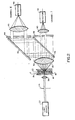
- Fig. 2 particularly illustrates the illumination optics 21 and detection optics 23 of Fig. 1 which are utilized to illuminate, in turn, each red blood cell 20 as it passes through flow cell 16 and to detect and measure the light scattered by such cell.
- the illumination optics comprises a light source 22, which may comprise a laser or a tungsten-halogen lamp.
- the illuminated field is defined by a precision slit aperture 24 which is imaged in the center of the sheathed sample stream 17 passing through flow cell 16 by an imaging lens 26.
- a laser illuminated field may be defined by an appropriate lens arrangement in lieu of the precision slit aperture 24.
- each sphered red blood cell passes, in turn, through the view volume of flow cell 16, it interrupts the light beam. Accordingly, light is scattered mainly in the forward direction and in an angular intensity pattern which, as defined by the laws of scattering of electromagnetic radiation, is a function, inter alia, of the HC and V of the red blood cell. Such patterns are more particularly described with respect to Figs. 3A-3C.
- the detection optics include a lens 30 which collects the forward scattered light 32 and collimates the same, as illustrated.
- the forward scattered light within two critical angular intervals 81 to ⁇ 1+ ⁇ 1 and 82 to ⁇ 2+ ⁇ 2 (hereafter (81, A81) and (02, A02), respectively), are separately detected and measured to precisely determine the HC and V of each individual red blood cell.
- the light from lens 30 is directed to a beam splitter 34 which transmits approximately half the light and reflects the remaining light.
- the reflected light is directed to and reflected from a mirror 36.
- Light scattered at the low angular interval (81, ⁇ 1) and at the high angular interval (82, A82) is measured in channel I and channel II, respectively.
- light passed through the beam splitter 34 is directed along channel I through an annular opening in a dark field stop 38 adapted to pass light scattered within the low angular interval (81, ⁇ 1).
- Light passed by stop 38 is collected by lens 40 and focused onto a detector 42.
- light reflected from mirror 36 is directed along channel II, which includes another annular opening in a dark field stop 44 adapted to pass light scattered within the high angular interval (82, ⁇ 2).
- Such light is collected by a second lens 46 and imaged onto a detector 48.
- the output of detector 42 is indicative of the amount of forward light scattered by a red blood cell within low angular interval (81, ⁇ 1) and the output of detector 48 is indicative of the amount of forward light scattered by a red blood cell within the high angular interval (82, ⁇ 2).
- such low and high angular intervals are selected such that light contained within these angular intervals contains sufficient information for the accurate and precise determi- . nation of the HC and V of the red blood cell being illuminated.
- the transmission-reflection characteristics of beam splitter 34 are such that the intensities of the light incident upon detectors 42 and 48 are approximately equal, so as to maximjze the signal-to-noise ratio of the system.
- Figs. 3A-3C illustrate the so-called differential intensity patterns, or angular distributions, of light scattered by individual sphered red blood cells uniformly illuminated by a collimated light beam, of the indicated hemoglobin concentrations and volumes passing through the flow cell 16.
- the angular distributions have been multipled by sin 8 and, therefore, are proportional to the light intensity scattered per unit scattering angle 8.
- spherical particles e.g., a non-nucleated, sphered red blood cell
- the light scattered in the forward direction by a spherical particle has an angular distribution which is a function of the wavelength of the incident light ( ⁇ ), the volume V (or equivalently the diameter) of the red blood cell, the hemoglobin concentration HC of the red blood cell (which determines its index of refraction) and the index of refraction of the medium in which the red blood cell is suspended, i.e. of the core stream 17.
- the index of refraction of the core stream 17 is determined solely by the physical properties of the sphering reagent (mainly water), to which the index of refraction of the sheath stream 19 is intentionally matched.
- the matched indices of refraction of the core and sheath streams 17 and 19 is hereafter referred to as n.
- the signal S generated by the detection of the forward scattered light can be represented mathematically by the equation where (8, ⁇ ) represents the angular interval within which such scattered light is detected.
- the apparatus parameters A, 8, ⁇ and n in such equation are fixed.
- equations (1) and (2) have only two unknowns, i.e. HC and V. If the system parameters are chosen correctly, these two equations (1) and (2) can be solved for the two unknowns. If equations (1) and (2) were linear in HC and V, the values of the coefficients multiplying the two unknown variables would depend upon the values of the system parameters and such equations would have unique solutions if the value of the determinant of these coefficients was not zero. However, equations (1) and (2) are, in fact, not linear equations.
- the so-called Jacobian determinant of equations (1) and (2) plays a role similar to the determinant of coefficients in the linear case. That is, the value of the Jacobian determinant, which depends upon HC, V, and the system parameters, must be non-zero if equations (1) and (2) are to yield single-valued solutions.
- the range of HC and V values for which the Jacobian determinant has non-zero values is dependent upon the values of the system parameters.
- the behavior of the Jacobian determinant can be used as a criterion when selecting the system parameters.
- equations (1) and (2) do not necessarily possess unique solutions for HC and V for all values of the angular parameters.
- This invention is based upon the discovery that a precise selection of the angular parameters (81, A81) and (82, ⁇ 2) can be made, given the other fixed parameters of the system i.e. ⁇ 1 and n, such that equations (1) and (2) can be solved for unique values of HC and V over defined ranges.
- ranges would be typically 30 fl to 150 fl for V and 22 g/dl to 46 g/dl for HC which includes both the known normal and abnormal ranges for human red cells.
- the respective magnitudes of the scattered light signals S1 and S2, represented by equations (1) and (2), respectively, are dependent upon HC because of the linear relationship of the index of refraction of the red blood cell (n c ) and the cellular hemoglobin concentration HC.
- Such linear relationship is expressed as In equation (3), the constant A is the index of refraction the red cell would have if HC were reduced to zero (approximately 1.33, the index of refraction of an isotonic aqueous solution at 0.6328 pm).
- B is the specific refraction increment of hemoglobin (approximately 0.0019 dl/g if HC is measured in g/dl).
- equations (1) and (2) can be replaced with equations in which n c appears instead of HC and the measurement technique of the invention would apply to the simultaneous measurement of the volume V and the index of refraction n c of any spherical dielectric particle.
- n c is a complex number having a real part, n CR' and an imaginary part, n CI'
- n CR is related to HC, as in equation (3)
- n CI is related to HC through the equation where e mM is the molecular extinction coefficient of the hemoglobin at wavelength ⁇ .
- n cR and n CI are not independent variables but are both dependent upon HC as in equations (3) and (4).
- equations (1) and (2) allow the determination of the volume and index of refraction of spherical dielectric particles, where such particles are either non-absorbing or, if absorbing, the real and imaginary parts of the index of refraction, n CR and n CI' respectively, are related by a common factor.
- Figs. 3A-3C illustrate the intensities as a function of scattering angle, in arbitrary units, of light scattered in the forward direction by sphered red blood cells of 120 fl, 90 fl and 60 fl, respectively, passing in a sheath stream and through a light beam having a wavelength of 0.6328 ⁇ m.
- the matched index of refraction n of the core and sheath streams is 1.3303. It will be appreciated that other wavelengths in the ultraviolet, visible or near infrared region of the spectrum can be used.
- such wavelength is one, such as 0.6328 ⁇ m, which is only minimally absorbed by the red cell.
- Figs. 3A-3C illustrate the variations in the forward scattered intensity pattern due to variations in the index of refraction of the red blood cell, the latter being linearly related to the HC of such cell as per equation (3).
- Figs. 3A-3C show the intensity patterns for HC values of 31 g/dl, 34 g/dl and 37 g/ dl, as indicated. With respect to such patterns, it should be appreciated that the typical volume V of a normal red cell is 90 fl and the typical hemoglobin concentration HC of such cell is 34 g/dl.
- the physiological range of V is between 60 fl and 120 fl and the physiological range of HC is between 31 g/dl. and 37 g/dl.
- the selections of (81, A81) and (82, ⁇ 2) are made by considering the angular dependence of the scattering patterns over these ranges, as illustrated in Figs. 3A-3C.
- the selection of the (81, A81) is made to provide that the signal S1 varies significantly with variations of V.
- the (81, ⁇ 1) is selected to give an interval which is in the region (preferably spanning) the first maximum of each of the scattering patterns over the physiological range of V.
- the first maximum for the middle value of V i.e., 90 fl, is 21 ⁇ 4° off the optical axis.
- the first maximum for the smallest value of V in the physiological range i.e., 60 fl
- the first maximum of the largest value of V in the physiological range i.e. 120 fl
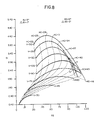
- the scattered light signal S1 detected within this angular interval varies as a function of both HC and V, yielding a S1 signal plotted against V and HC (where V varies between 30 fl and 150 fl and HC varies between 22 g/dl to 46 g/dl) as illustrated in Fig. 4.
- Fig. 4 shows that for a given value of S1, V is multivalued for certain values of HC. That is, for a given HC in the range 40 g/dl through 46 g/dl and for certain values of S1, V has two possible values.
- the red blood cell may have a volume V of 120 fl or 74 fl, as indicated by points a and b respectively, in Fig. 4.
- This phenomenon is a manifestation of the fact which there can be many pairs of V and HC values which satisfy equation (1) for S1.
- the high angle interval (82, ⁇ 2) is selected such as to resolve the ambiguities in the values of HC and V satisfying equation (1) for S1.
- Such . resolution is achieved by selecting (62, ⁇ 2) to span a range of angles in the region above the first maximum of the scattering patterns obtained over the physiological ranges of HC and V.
- Such high angular interval (62, ⁇ 2) is selected, in the preferred embodiment, such that signal S2 varies monotonically with both HC and V over the range of interest.
- the secondary maxima of the scattering patterns increase in amplitude with both increasing HC and increasing V.
- the positions of these secondary maxima are very dependent on V and this positional variation will cause S2 to be non-monotonic unless (82, A82) is wide enough to smooth or render ineffective the positional variability of such secondary maxima.
- the interval ⁇ 2 is preferably selected to be as large as possible consistent with practical optical considerations and signal-to-noise requirements of the system. The point whereat the scattering intensity in Figs. 3A-3C reduce essentially to zero, e.g.
- each sphered red blood cell intercepting the light beam from source 22 produces a pair of signals S1 and S2, whose respective magnitudes are functions of both the HC and V of such cell.
- the respective magnitudes of S1 and S2 are indicative of that HC-V pair which characterizes such cell.
- Each such pair of S1 and S2 signals can be plotted as a point in a S1-S2 plane, as illustrated in Fig. 6.
- the HC and V of the red blood cell can be determined with the required precision.
- the solid curves indicate variations of S1 and S2 as a function of HC for fixed values of V and the dashed curves indicate variations of S1 and S2 as a function of V for fixed values of HC.
- a single point in the S1-S2 plane represents a single HC-V pair, precisely identifying a single red blood cell with these characteristics.
- point c represents a unique solution of equations (1) and (2) and represents a red blood cell having a V of 75 fl and an HC of 37 g/dl.
- the resulting S1-S2 plot may have indeterminate points, that is, single points which are indicative of more than one HC-V pair. Such condition would result, for example, when both S1 and S2 are not monotonic when plotted against HC and V over the desired dynamic ranges of HC and V. Hence, unique solutions of equations (1) and (2) for HC and V would not exist for all values of S1 and S2.
- Point d is representative of a V value of 90 fl and an HC value of 40 g/dl and, also, a V value of 105 fl and HC value of 42 g/dl.
- point e is representative of a V value of 75 fl and an HC value of 41 g/dl and also a V value of 120 fl and an HC value of 44 g/dl. Any point falling within the fold- over portion of the S1-S2 plot of Fig.
- equations (1) and (2) are solvable, numerical tables are employed which map S1-S2 pairs into unique HC-V pairs. Such tables are based upon the system parameters, i.e., 01, A81, 82, A82, n and A. Such tables are stored as a look-up table in a decoding memory 50, as shown in Fig. 1, which is capable of receiving the S1 and S2 values and reporting the HC and V of each red blood cell. Such a table is precomputed using electromagnetic scattering theory and includes all resolvable HC-V pairs within the practical range of cell parameters to be measured. Alternatively, such HC-V pairs can be generated by real-time computation.
- the outputs of detectors 42 and 48 which are proportional to the scattered light intensities within the low angular interval (81, A81) and the high angular interval (82, ⁇ 2), respectively, are amplified by amplifiers 52 and 54, respectively.
- the nominal gains of amplifiers 52 and 54 i.e., G1 and G2, respectively, are adjustable to allow for calibration of the system.
- amplifiers 52 and 54 preferably, include automatic gain control (AGC) to compensate for small variations which might occur in the intensity of the light beam.
- AGC automatic gain control
- the respective outputs of amplifiers 52 and 54 are directed to peak detectors 56 and 58, respectively, which are of conventional design.
- the output of amplifier 54 is applied along lead 55 to an input of a controller 60 which, upon receiving a signal from amplifier 54, applies a control pulse along lead 57 to peak detector 56 and 58.
- Peak detectors 56 and 58 track the output signals of amplifiers 52 and 54 and, then, store the peak value of such signals.
- the peak values stored in peak detectors 56 and 58 which are indicative of S1 and S2, respectively, are applied to the inputs of A/D converters 62 and 64, respectively.
- pulse integrating techniques can be used in lieu of peak detecting techniques to generate the S1 and S2 signals.
- controller 60 generates a convert pulse along lead 59, to enable the A/D converters 62 and 64 to each generate 6-bit signals along bus 61 and bus 63, indicative of the values of the S1 and S2 signals, respectively. Accordingly, the S1 and S2 signals, now digitized, are used to address memory 50 to retrieve the particular HC-V pair represented by the S1 and S2 signals. Concurrently, controller 60 applies a control pulse along lead 69 to activate a histogram accumulator 66.
- the outputs of the memory 50 i.e., the HC and V values
- Histogram accumulator 66 comprises a memory of 16K words wherein each memory word corresponds to a particular pair of HC and V values and is incremented, i.e., an add-one operation is performed, whenever a measurement produces those values of HC and V.
- controller 60 When a given number of red blood cells have been measured, controller 60.applies a control pulse along lead 73, directing a display controller 68 to read accumulator 66 ' along bus 71 and activate display 70 to produce displays of individual histograms 72 and 74 of V and HC, respectively, and also a two-dimensional frequency distribution 76 of HC-V pairs which characterize the red blood cells in the measured sample. It is a significant feature of the invention that the frequency distribution of V and HC of the individual red blood cells in the measured sample are displayed, as by histograms 72 and 74, respectively, along with the statistical correlation of HC and V contained in the two-dimensional frequency distribution 76, providing significant information to the diagnostician.
- display 70 may have the capability to provide a paper printout or hard copy of histograms 72 and 74 and also of the two-dimensional distribution 76. It should be evident that the histograms 72 and 74 and the two dimensional distribution 76 can be reported individually or in any combination.
- the red blood cell indices MCV and MCHC are readily obtained from the volume histogram 72 and hemoglobin concentration histogram 74, respectively, by calculation of the mean values of the two histograms using standard statistical methods. Also, the widths of the two histograms, 72 and 74, are readily characterized by standard deviations and/or coefficients of variation, again using standard statistical methods. It should be appreciated that the present invention provides a means of quantitatively measuring the amount of red cell color variation in a sample of blood, something that heretofore has not been possible using flow cytometry techniques.
- the standard deviation of the HC histogram 74 is such a measure since it measures the amount of cell-to-cell HC variation in the sample which, in turn, is responsible for the amount of cell-to-cell color variation in the sample.
- the coefficient of variation of the volume histogram 72 measures the so-called RDW index of the blood sample, a standard hematological parameter measured by instruments such as the TECHNICON H-6000 system and the Coulter Model "S" system.
- the method described is applicable to the measurement of the volume and index of refractions of any spherical dielectric particle, which is either non-absorbing or absorbing as described above.
- a water-immiscible oil droplet passed through the flow cell could be measured for these parameters.
- the index of refraction is known and is within the range, for example, encompassed by human red blood cells, such oil droplets can be used to calibrate the system.
- a suspension of such oil droplets, naturally sphered by surface tension forces, and having varying volumes within the range to be measured, are entrained in the sheath stream 19 and passed through the viewing volume of the flow cell 16.
- Each oil particle intercepts the light beam and produces a forward scattering pattern of the type illustrated in Figs. 3A-3C.
- the forward scattered signals within the low angular interval (81, A81) and the high angular interval (82, ⁇ 2) are measured to generate corresponding S1 and S2 signals, respectively.
- the S1 and S2 signals are passed through the system of Fig. 1, as described above, and the resulting HC histogram 74 is examined. Since all oil droplets have the same index of refraction, such a histogram consists of a very narrow peak.
- oil droplets having several distinct indices of refraction e.g., three, are employed to produce three distinct very narrow peaks in HC histogram 74.
- the proper calibration of the system is obtained by adjusting the gains G1 and G2 of amplifiers 52 and 54, respectively, to simultaneously minimize the widths of each of the three peaks. Accordingly, after calibration, pairs of S1 and S2 values produced by A/D converters 62 and 64, respectively, have the correct correspondence with HC-V pairs in the look-up table stored in memory 50. In effect, when the system is properly calibrated, the S1-S2 pairs obtained from oil droplet measurements would fall on a constant-HC curve corresponding to the refractive index of the oil when plotted on the grid of Fig. 6.
- each wavelength ⁇ 1 and ⁇ 2 can be used by utilizing a polychromatic light source for source 22 in Fig. 2.
- each wavelength ⁇ 1 and ⁇ 2 generates distinctive scattering patterns, qualitatively similar to those illustrated in Figs. 3A-3C, which vary as functions of HC and V of the scattering particle.
- Such patterns can be distinguished with respect to wavelength by proper optical techniques.
- a dichroic mirror is substituted for beam splitter 34, such mirror having transmission/reflection characteristics such that the scattering patterns of wavelengths ⁇ 1 and X2 are directed to detectors 42 and 48, respectively, which are made selectively responsive to light of wavelengths ⁇ 1 and A2, respectively.
- signals S1 and S2 are generated and directed to memory 50, as described above, which contains a precomputed table listing the corresponding HC-V pairs for each S1-S2 pair, whereby the appropriate histograms 72 and 74 of V and HC, respectively, and the two-dimensional frequency distribution 76 of the HC-V pairs are displayed.
- the two wavelength technique described maintains all apparatus parameters fixed in equations (1) and (2), except for the variable parameters V and HC.
- equations (1) and (2) remain the same, except that ⁇ 1 and ⁇ 2 are substituted for ⁇ equations (1) and (2), respectively.
- the angular interval (81, ⁇ 1) is selected such that signal S1 varies significantly with variations of V.
- the angular interval (02, ⁇ 2) is selected such as to resolve ambiguities in the values of HC and V in equation (1). (81, ⁇ 1) and (02, ⁇ 2) are selected as described above.
- (81, ⁇ 1) and (82, ⁇ 2) may overlap in part or completely.
- the forward light scattering pattern tends to become compressed in the direction of smaller scattering angles as the wavelength of the light is increased. Accordingly, it is possible that the first maximum of the forward light scattering pattern of ⁇ 1 may fall within the angular region of the secondary maxima in the forward light scattering pattern of X2. Therefore, by proper selection of ⁇ 1 and A2, the angular intervals (81, ⁇ 1) and (82, ⁇ 2) may be overlapping or even equal. In the latter case, dark field stops 38 and 44 of Fig. 2 would be identical and adapted to pass the same angular interval of the scattered light patterns.
- alternative embodiments of the present invention involve so-called extinction measurements for either or both S1 and S2 instead of the scattering measurements discussed above.
- the corresponding angular interval, described above would usually be defined by an annular aperture, rather than by an annular stop.
- the extinction, or reduction, of light passing through such aperture due to interception of the light beam by the particle would be approximately equal to that scattered into the angular interval discussed above.
- the measurement of S2 by an extinction method is essentially equivalent to measurement by the scattering method, as described above.
- a further modification of the extinction method would make S2 an absorption measurement by using a small A02 (e.g. approximately equal to the divergence angle of the illumination beam), such as in the system of H. M. Shapiro et al, discussed above.
- the preferred embodiment has been described with respect to sphered red blood cells.
- the invention is applicable to the measurement of particles which are slightly deformed from the spherical and also non-spherical particles.
- the measurements of HC and V would be less accurate than those for strictly spherical particles, the loss of accuracy depending upon the degree of deformation.
- additional variables are introduced into the system. In such event, and depending upon the number of additional variables introduced, more than two angular intervals, which may or may not include (81, ⁇ 1) and (82, A02), would be employed in the measurements.
- flow cell 16 is structured to define a particular geometry of the core stream 17 such that the axis of rotational symmetry of the particles are all forced into a similar orientation with respect to the axis of the optical system.
- the index of refraction remains an independent variable. Accordingly, as the number of variables to be measured is increased to three, light scattered at three selected angular intervals would be measured to determine both the volume and index of refraction of the spheroidal particle.
Claims (20)
Applications Claiming Priority (2)
| Application Number | Priority Date | Filing Date | Title |
|---|---|---|---|
| US06/547,513 US4735504A (en) | 1983-10-31 | 1983-10-31 | Method and apparatus for determining the volume & index of refraction of particles |
| US547513 | 1983-10-31 |
Publications (2)
| Publication Number | Publication Date |
|---|---|
| EP0140616A1 EP0140616A1 (fr) | 1985-05-08 |
| EP0140616B1 true EP0140616B1 (fr) | 1988-03-09 |
Family
ID=24184946
Family Applications (1)
| Application Number | Title | Priority Date | Filing Date |
|---|---|---|---|
| EP84306942A Expired EP0140616B1 (fr) | 1983-10-31 | 1984-10-11 | Méthode et appareil pour déterminer le volume et l'indice de réfraction de particules |
Country Status (6)
| Country | Link |
|---|---|
| US (1) | US4735504A (fr) |
| EP (1) | EP0140616B1 (fr) |
| JP (2) | JPH0820442B2 (fr) |
| AU (1) | AU578622B2 (fr) |
| CA (1) | CA1230752A (fr) |
| DE (1) | DE3469804D1 (fr) |
Cited By (13)
| Publication number | Priority date | Publication date | Assignee | Title |
|---|---|---|---|---|
| US7713687B2 (en) | 2000-11-29 | 2010-05-11 | Xy, Inc. | System to separate frozen-thawed spermatozoa into x-chromosome bearing and y-chromosome bearing populations |
| US7723116B2 (en) | 2003-05-15 | 2010-05-25 | Xy, Inc. | Apparatus, methods and processes for sorting particles and for providing sex-sorted animal sperm |
| US7758811B2 (en) | 2003-03-28 | 2010-07-20 | Inguran, Llc | System for analyzing particles using multiple flow cytometry units |
| US7820425B2 (en) | 1999-11-24 | 2010-10-26 | Xy, Llc | Method of cryopreserving selected sperm cells |
| US7833147B2 (en) | 2004-07-22 | 2010-11-16 | Inguran, LLC. | Process for enriching a population of sperm cells |
| US7838210B2 (en) | 2004-03-29 | 2010-11-23 | Inguran, LLC. | Sperm suspensions for sorting into X or Y chromosome-bearing enriched populations |
| US7855078B2 (en) | 2002-08-15 | 2010-12-21 | Xy, Llc | High resolution flow cytometer |
| US7929137B2 (en) | 1997-01-31 | 2011-04-19 | Xy, Llc | Optical apparatus |
| US8137967B2 (en) | 2000-11-29 | 2012-03-20 | Xy, Llc | In-vitro fertilization systems with spermatozoa separated into X-chromosome and Y-chromosome bearing populations |
| US8211629B2 (en) | 2002-08-01 | 2012-07-03 | Xy, Llc | Low pressure sperm cell separation system |
| US8486618B2 (en) | 2002-08-01 | 2013-07-16 | Xy, Llc | Heterogeneous inseminate system |
| US9145590B2 (en) | 2000-05-09 | 2015-09-29 | Xy, Llc | Methods and apparatus for high purity X-chromosome bearing and Y-chromosome bearing populations of spermatozoa |
| US9365822B2 (en) | 1997-12-31 | 2016-06-14 | Xy, Llc | System and method for sorting cells |
Families Citing this family (84)
| Publication number | Priority date | Publication date | Assignee | Title |
|---|---|---|---|---|
| NO156916C (no) * | 1985-07-10 | 1987-12-16 | Harald B Steen | Stroemningskammer for vaeskestroemsfotometer. |
| NO156917C (no) * | 1985-07-16 | 1987-12-16 | Harald B Steen | Anordning for maaling av biologiske cellers lysspredning i vaeskestroemsfotometere. |
| GB8523747D0 (en) * | 1985-09-26 | 1985-10-30 | Vg Instr Group | Fibre size monitor |
| US4989978A (en) * | 1986-04-04 | 1991-02-05 | Technicon Instruments Corporation | Method and apparatus for determining the count per unit volume of particles |
| KR970007077B1 (ko) * | 1987-03-13 | 1997-05-02 | 코울터 일렉트로닉스 인커퍼레이티드 | 광산란 기술을 이용한 다중-부분식별 분석 방법 |
| JP2635126B2 (ja) * | 1988-09-30 | 1997-07-30 | 東亜医用電子株式会社 | 核の分葉指数を求めるための粒子分析装置及び方法 |
| JP2815435B2 (ja) * | 1989-12-22 | 1998-10-27 | 株式会社日立製作所 | 粒子解析装置及び血球カウンタ |
| US5037202A (en) * | 1990-07-02 | 1991-08-06 | International Business Machines Corporation | Measurement of size and refractive index of particles using the complex forward-scattered electromagnetic field |
| US5194909A (en) * | 1990-12-04 | 1993-03-16 | Tycko Daniel H | Apparatus and method for measuring volume and hemoglobin concentration of red blood cells |
| US5133602A (en) * | 1991-04-08 | 1992-07-28 | International Business Machines Corporation | Particle path determination system |
| AU680143B2 (en) * | 1991-12-05 | 1997-07-17 | Bayer Corporation | Methods and reagent compositions for use in the identification and characterization of reticulocytes in whole blood |
| US5360739A (en) * | 1991-12-05 | 1994-11-01 | Miles Inc. | Methods for the identification and characterization of reticulocytes in whole blood |
| US5350695A (en) * | 1991-12-05 | 1994-09-27 | Miles Inc. | Methods for the identification and characterization of reticulocytes in whole blood |
| US5284771A (en) * | 1991-12-05 | 1994-02-08 | Miles Inc. | Reagent compositions and their use in sphering cells |
| US6509192B1 (en) * | 1992-02-24 | 2003-01-21 | Coulter International Corp. | Quality control method |
| US5331958A (en) * | 1992-03-31 | 1994-07-26 | University Of Manitoba | Spectrophotometric blood analysis |
| US5859705A (en) * | 1993-05-26 | 1999-01-12 | The Dow Chemical Company | Apparatus and method for using light scattering to determine the size of particles virtually independent of refractive index |
| US6271916B1 (en) | 1994-03-24 | 2001-08-07 | Kla-Tencor Corporation | Process and assembly for non-destructive surface inspections |
| US5601080A (en) * | 1994-12-28 | 1997-02-11 | Coretech Medical Technologies Corporation | Spectrophotometric blood analysis |
| US5733739A (en) * | 1995-06-07 | 1998-03-31 | Inphocyte, Inc. | System and method for diagnosis of disease by infrared analysis of human tissues and cells |
| JP2000502446A (ja) * | 1995-12-18 | 2000-02-29 | センター フォー ラボラトリー テクノロジー,インク. | 血液診断装置及び判定方法 |
| US6025201A (en) * | 1995-12-28 | 2000-02-15 | Bayer Corporation | Highly sensitive, accurate, and precise automated method and device for identifying and quantifying platelets and for determining platelet activation state using whole blood samples |
| US5817519A (en) * | 1995-12-28 | 1998-10-06 | Bayer Corporation | Automated method and device for identifying and quantifying platelets and for determining platelet activation state using whole blood samples |
| US5686309A (en) * | 1996-01-19 | 1997-11-11 | Coulter International Corp. | Method and apparatus for determination of hemoglobin content of individual red blood cells |
| US5835211A (en) * | 1996-03-28 | 1998-11-10 | Particle Sizing Systems, Inc. | Single-particle optical sensor with improved sensitivity and dynamic size range |
| US6136182A (en) * | 1996-06-07 | 2000-10-24 | Immunivest Corporation | Magnetic devices and sample chambers for examination and manipulation of cells |
| US6660159B1 (en) | 1996-06-07 | 2003-12-09 | Immunivest Corporation | Magnetic separation apparatus and methods |
| US6790366B2 (en) * | 1996-06-07 | 2004-09-14 | Immunivest Corporation | Magnetic separation apparatus and methods |
| US6890426B2 (en) * | 1996-06-07 | 2005-05-10 | Immunivest Corporation | Magnetic separation apparatus and methods |
| US7666308B2 (en) * | 1996-06-07 | 2010-02-23 | Veridex, Llc. | Magnetic separation apparatus and methods |
| US5993665A (en) * | 1996-06-07 | 1999-11-30 | Immunivest Corporation | Quantitative cell analysis methods employing magnetic separation |
| US5844685A (en) * | 1996-07-30 | 1998-12-01 | Bayer Corporation | Reference laser beam sampling apparatus |
| US5872627A (en) * | 1996-07-30 | 1999-02-16 | Bayer Corporation | Method and apparatus for detecting scattered light in an analytical instrument |
| US5830764A (en) * | 1996-11-12 | 1998-11-03 | Bayer Corporation | Methods and reagent compositions for the determination of membrane surface area and sphericity of erythrocytes and reticulocytes for the diagnosis of red blood cell disorders |
| US5798827A (en) * | 1996-11-26 | 1998-08-25 | Coulter International Corp. | Apparatus and method for determination of individual red blood cell shape |
| US6413715B2 (en) | 1997-01-31 | 2002-07-02 | The Collaborative Group | β(1-3)-glucan diagnostic assays |
| US6114173A (en) * | 1997-04-03 | 2000-09-05 | Bayer Corporation | Fully automated method and reagent composition therefor for rapid identification and characterization of reticulocytes erythrocytes and platelets in whole blood |
| JPH10307135A (ja) * | 1997-05-02 | 1998-11-17 | Toa Medical Electronics Co Ltd | 赤血球形態異常の検出方法 |
| US6074879A (en) * | 1997-06-23 | 2000-06-13 | Bayer Corporation | Synthetic polymer particles for use as standards and calibrators in flow cytometry |
| US5874310A (en) * | 1997-11-21 | 1999-02-23 | Coulter International Corp. | Method for differentiation of nucleated red blood cells |
| US5917584A (en) * | 1997-11-21 | 1999-06-29 | Coulter International Corp. | Method for differentiation of nucleated red blood cells |
| WO2000058727A1 (fr) * | 1999-03-31 | 2000-10-05 | Bayer Corporation | Canal unique, procédé de détection par dilution unique |
| US6190919B1 (en) * | 1999-04-21 | 2001-02-20 | The United States Of America As Represented By The Secretary Of The Navy | System for controlling deglycerolization of red blood cells |
| FR2801671B1 (fr) * | 1999-11-29 | 2001-12-21 | Commissariat Energie Atomique | Dispositif de mesure, par diffraction, de tailles de particules sensiblement spheriques, notamment de gouttes opaques |
| US6421121B1 (en) * | 2000-02-10 | 2002-07-16 | Micro Imaging Technology | Method and apparatus for rapid particle identification utilizing scattered light histograms |
| US6784981B1 (en) | 2000-06-02 | 2004-08-31 | Idexx Laboratories, Inc. | Flow cytometry-based hematology system |
| WO2002025247A2 (fr) | 2000-09-20 | 2002-03-28 | Menguc M Pinar | Procede et appareil non intrusifs permettant de caracteriser des particules par diffusion d'elements matriciels au moyen d'une radiation polarisee elliptiquement |
| US6538730B2 (en) * | 2001-04-06 | 2003-03-25 | Kla-Tencor Technologies Corporation | Defect detection system |
| US6630990B2 (en) * | 2001-06-05 | 2003-10-07 | Abbott Laboratories | Optical method and apparatus for red blood cell differentiation on a cell-by-cell basis, and simultaneous analysis of white blood cell differentiation |
| CA2428740A1 (fr) | 2002-05-20 | 2003-11-20 | Bayer Corporation | Methode automatisee et reactif pour le dosage de liquides organiques tels que le liquide cephalorachidien (lcr) |
| US7116413B2 (en) * | 2002-09-13 | 2006-10-03 | Kla-Tencor Corporation | Inspection system for integrated applications |
| US7169548B2 (en) | 2002-09-13 | 2007-01-30 | Xy, Inc. | Sperm cell processing and preservation systems |
| US7092078B2 (en) | 2003-03-31 | 2006-08-15 | Nihon Kohden Corporation | Flow cytometer for classifying leukocytes and method for determining detection angle range of the same |
| US7095492B2 (en) * | 2003-12-19 | 2006-08-22 | Beckman Coulter, Inc. | Method and apparatus for measuring cell-by-cell hemoglobin |
| JP4417143B2 (ja) * | 2004-03-11 | 2010-02-17 | シスメックス株式会社 | 試料分析装置、プログラムおよびそのプログラムを記録した記録媒体 |
| US7081227B2 (en) * | 2004-06-07 | 2006-07-25 | The Reagents Of The University Of California | Amphiphilic mediated sample preparation for micro-flow cytometry |
| US7420669B2 (en) * | 2004-07-01 | 2008-09-02 | Midwest Research Institute | Optic probe for semiconductor characterization |
| FR2883971B1 (fr) * | 2005-03-31 | 2007-11-16 | C2 Diagnostics Sa | Dispositif optique d'analyse sanguine, appareil d'analyse equipe d'un tel dispositif |
| FR2884920B1 (fr) * | 2005-04-21 | 2007-08-10 | Horiba Abx Sa Sa | Dispositif et procede d'analyse multiparametrique d'elements microscopiques |
| US7315372B1 (en) | 2005-09-29 | 2008-01-01 | The United States Of America As Represented By The Secretary Of The Navy | Instrument using near-field intensity correlation measurements for characterizing scattering of light by suspensions |
| US7354767B2 (en) * | 2006-03-16 | 2008-04-08 | Beckman Coulter, Inc. | Reference control composition containing a nucleated red blood cell component made of non-nucleated blood cells |
| JP5010443B2 (ja) * | 2006-12-20 | 2012-08-29 | シスメックス株式会社 | 血球分析装置および血球分析方法 |
| JP4949898B2 (ja) * | 2007-03-09 | 2012-06-13 | シスメックス株式会社 | 血球分析装置 |
| WO2010108020A1 (fr) * | 2009-03-20 | 2010-09-23 | Bio-Rad Laboratories, Inc. | Cytométrie en flux avec microscopie et imagerie en fluorescence multicolore codée par balayage linéaire en série |
| EP2425241A4 (fr) | 2009-04-27 | 2015-05-13 | Abbott Lab | Procede de discrimination des globules rouges des globules blancs par utilisation de la diffusion vers l'avant d'un laser dans un analyseur hematologique automatise |
| US8906308B2 (en) | 2010-01-15 | 2014-12-09 | Abbott Laboratories | Method for determining volume and hemoglobin content of individual red blood cells |
| FR2956207B1 (fr) | 2010-02-10 | 2012-05-04 | Horiba Abx Sas | Dispositif et procede de mesures multiparametriques de microparticules dans un fluide |
| JP5533055B2 (ja) * | 2010-03-10 | 2014-06-25 | ソニー株式会社 | 光学的測定装置及び光学的測定方法 |
| WO2012058381A2 (fr) * | 2010-10-27 | 2012-05-03 | The General Hospital Corporation | Appareil, systèmes et méthodes de mesure de la pression sanguine dans au moins un vaisseau |
| WO2013080209A1 (fr) * | 2011-12-01 | 2013-06-06 | P.M.L. - Particles Monitoring Technologies Ltd. | Système de détection pour la mesure de la taille et de la concentration de particules |
| JP6076801B2 (ja) * | 2013-03-29 | 2017-02-08 | シスメックス株式会社 | 血球分析装置および血球分析方法 |
| US10443159B2 (en) | 2013-08-15 | 2019-10-15 | Arun Agarwal | Proliferated thread count of a woven textile by simultaneous insertion within a single pick insertion event of a loom apparatus multiple adjacent parallel yarns drawn from a multi-pick yarn package |
| RU2550159C2 (ru) * | 2013-08-20 | 2015-05-10 | Государственное Научное Учреждение "Институт Физики Имени Б.И. Степанова Национальной Академии Наук Беларуси" | Способ определения показателя преломления частиц, образующих многослойную упорядоченную структуру (варианты) |
| CN104515723B (zh) * | 2013-09-30 | 2017-12-05 | 深圳迈瑞生物医疗电子股份有限公司 | 细胞分析仪及其红细胞凝集报警方法和系统 |
| FR3022347B1 (fr) * | 2014-06-17 | 2018-01-12 | Ecole Superieure De Physique Et De Chimie Industrielles De La Ville De Paris | Particules liquides biomimetiques, procede et dispositif de mesure en cytometrie en flux |
| JP6352750B2 (ja) * | 2014-09-26 | 2018-07-04 | シスメックス株式会社 | 血液分析装置および血液分析方法 |
| JP6370659B2 (ja) | 2014-09-26 | 2018-08-08 | シスメックス株式会社 | 血液分析装置および血液分析方法 |
| CN108291863B (zh) * | 2015-10-02 | 2020-07-03 | 国家光学研究所 | 用于使用光散射技术进行个体颗粒尺寸测量的系统和方法 |
| DE102017121587B4 (de) * | 2017-09-18 | 2023-09-14 | Bundesrepublik Deutschland, Vertreten Durch Das Bundesministerium Für Wirtschaft Und Energie, Dieses Vertreten Durch Den Präsidenten Der Physikalischen Bundesanstalt | Verfahren zum simultanen Bestimmen von Proben-Eigenschaften und Partikelmess-Vorrichtung |
| JP6791081B2 (ja) * | 2017-09-26 | 2020-11-25 | 株式会社島津製作所 | 屈折率測定装置及び屈折率測定方法 |
| KR20230156814A (ko) | 2017-10-26 | 2023-11-14 | 파티클 머슈어링 시스템즈, 인크. | 입자 측정을 위한 시스템 및 방법 |
| EP3959505B1 (fr) | 2019-04-25 | 2024-05-08 | Particle Measuring Systems, Inc. | Systèmes et procédés de détection de particules pour la détection de particules sur axe et/ou la détection différentielle |
| EP4133251A4 (fr) * | 2020-04-08 | 2024-04-17 | Commissariat Energie Atomique | Procédé de détermination de la viabilité de cellules |
| CN113720741A (zh) * | 2021-07-27 | 2021-11-30 | 深圳市正精达仪器有限公司 | 烟尘浓度的检测方法、装置、终端设备及介质 |
Family Cites Families (11)
| Publication number | Priority date | Publication date | Assignee | Title |
|---|---|---|---|---|
| US3705771A (en) * | 1970-01-14 | 1972-12-12 | Bio Physics Systems Inc | Photoanalysis apparatus |
| BE793185A (fr) * | 1971-12-23 | 1973-04-16 | Atomic Energy Commission | Appareil pour analyser et trier rapidement des particules telles que des cellules biologiques |
| CH549210A (de) * | 1972-09-14 | 1974-05-15 | Contraves Ag | Verfahren und messgeraet zur bestimmung des wahren mittleren volumens von in einer elektrolytisch leitenden fluessigkeit suspendierten teilchen. |
| JPS522494A (en) * | 1975-06-13 | 1977-01-10 | Science Spectrum | Method and apparatus for testing a reaction of microbody against an environment |
| US4173415A (en) * | 1976-08-20 | 1979-11-06 | Science Spectrum, Inc. | Apparatus and process for rapidly characterizing and differentiating large organic cells |
| US4134679A (en) * | 1976-11-05 | 1979-01-16 | Leeds & Northrup Company | Determining the volume and the volume distribution of suspended small particles |
| US4577964A (en) * | 1978-09-06 | 1986-03-25 | Ortho Diagnostics, Inc. | Apparatus and method for detecting platelets in whole blood |
| US4273443A (en) * | 1979-11-21 | 1981-06-16 | Coulter Electronics, Inc. | Method and apparatus for measurement of reradiation in particle flow cell systems |
| US4548500A (en) * | 1982-06-22 | 1985-10-22 | Wyatt Philip J | Process and apparatus for identifying or characterizing small particles |
| US4492752A (en) * | 1982-09-03 | 1985-01-08 | Ortho Diagnostics Systems Inc. | Method for discriminating between unstained and absorbing dye stained cells |
| JPS5981537A (ja) * | 1982-11-01 | 1984-05-11 | Japan Spectroscopic Co | 微小粒子分析装置 |
-
1983
- 1983-10-31 US US06/547,513 patent/US4735504A/en not_active Expired - Lifetime
-
1984
- 1984-08-28 CA CA000461953A patent/CA1230752A/fr not_active Expired
- 1984-08-29 AU AU32486/84A patent/AU578622B2/en not_active Ceased
- 1984-10-11 DE DE8484306942T patent/DE3469804D1/de not_active Expired
- 1984-10-11 EP EP84306942A patent/EP0140616B1/fr not_active Expired
- 1984-10-31 JP JP59228078A patent/JPH0820442B2/ja not_active Expired - Lifetime
-
1995
- 1995-07-21 JP JP7206747A patent/JP2526373B2/ja not_active Expired - Lifetime
Cited By (26)
| Publication number | Priority date | Publication date | Assignee | Title |
|---|---|---|---|---|
| US7929137B2 (en) | 1997-01-31 | 2011-04-19 | Xy, Llc | Optical apparatus |
| US9422523B2 (en) | 1997-12-31 | 2016-08-23 | Xy, Llc | System and method for sorting cells |
| US9365822B2 (en) | 1997-12-31 | 2016-06-14 | Xy, Llc | System and method for sorting cells |
| US7820425B2 (en) | 1999-11-24 | 2010-10-26 | Xy, Llc | Method of cryopreserving selected sperm cells |
| US9145590B2 (en) | 2000-05-09 | 2015-09-29 | Xy, Llc | Methods and apparatus for high purity X-chromosome bearing and Y-chromosome bearing populations of spermatozoa |
| US7713687B2 (en) | 2000-11-29 | 2010-05-11 | Xy, Inc. | System to separate frozen-thawed spermatozoa into x-chromosome bearing and y-chromosome bearing populations |
| US8652769B2 (en) | 2000-11-29 | 2014-02-18 | Xy, Llc | Methods for separating frozen-thawed spermatozoa into X-chromosome bearing and Y-chromosome bearing populations |
| US7771921B2 (en) | 2000-11-29 | 2010-08-10 | Xy, Llc | Separation systems of frozen-thawed spermatozoa into X-chromosome bearing and Y-chromosome bearing populations |
| US8137967B2 (en) | 2000-11-29 | 2012-03-20 | Xy, Llc | In-vitro fertilization systems with spermatozoa separated into X-chromosome and Y-chromosome bearing populations |
| US8211629B2 (en) | 2002-08-01 | 2012-07-03 | Xy, Llc | Low pressure sperm cell separation system |
| US8497063B2 (en) | 2002-08-01 | 2013-07-30 | Xy, Llc | Sex selected equine embryo production system |
| US8486618B2 (en) | 2002-08-01 | 2013-07-16 | Xy, Llc | Heterogeneous inseminate system |
| US7855078B2 (en) | 2002-08-15 | 2010-12-21 | Xy, Llc | High resolution flow cytometer |
| US8709817B2 (en) | 2003-03-28 | 2014-04-29 | Inguran, Llc | Systems and methods for sorting particles |
| US7943384B2 (en) | 2003-03-28 | 2011-05-17 | Inguran Llc | Apparatus and methods for sorting particles |
| US8664006B2 (en) | 2003-03-28 | 2014-03-04 | Inguran, Llc | Flow cytometer apparatus and method |
| US8709825B2 (en) | 2003-03-28 | 2014-04-29 | Inguran, Llc | Flow cytometer method and apparatus |
| US8748183B2 (en) | 2003-03-28 | 2014-06-10 | Inguran, Llc | Method and apparatus for calibrating a flow cytometer |
| US9040304B2 (en) | 2003-03-28 | 2015-05-26 | Inguran, Llc | Multi-channel system and methods for sorting particles |
| US7799569B2 (en) | 2003-03-28 | 2010-09-21 | Inguran, Llc | Process for evaluating staining conditions of cells for sorting |
| US7758811B2 (en) | 2003-03-28 | 2010-07-20 | Inguran, Llc | System for analyzing particles using multiple flow cytometry units |
| US9377390B2 (en) | 2003-03-28 | 2016-06-28 | Inguran, Llc | Apparatus, methods and processes for sorting particles and for providing sex-sorted animal sperm |
| US7723116B2 (en) | 2003-05-15 | 2010-05-25 | Xy, Inc. | Apparatus, methods and processes for sorting particles and for providing sex-sorted animal sperm |
| US7892725B2 (en) | 2004-03-29 | 2011-02-22 | Inguran, Llc | Process for storing a sperm dispersion |
| US7838210B2 (en) | 2004-03-29 | 2010-11-23 | Inguran, LLC. | Sperm suspensions for sorting into X or Y chromosome-bearing enriched populations |
| US7833147B2 (en) | 2004-07-22 | 2010-11-16 | Inguran, LLC. | Process for enriching a population of sperm cells |
Also Published As
| Publication number | Publication date |
|---|---|
| JP2526373B2 (ja) | 1996-08-21 |
| US4735504A (en) | 1988-04-05 |
| JPH0820442B2 (ja) | 1996-03-04 |
| JPS60115858A (ja) | 1985-06-22 |
| AU578622B2 (en) | 1988-11-03 |
| JPH0854388A (ja) | 1996-02-27 |
| DE3469804D1 (en) | 1988-04-14 |
| AU3248684A (en) | 1985-05-09 |
| CA1230752A (fr) | 1987-12-29 |
| EP0140616A1 (fr) | 1985-05-08 |
Similar Documents
| Publication | Publication Date | Title |
|---|---|---|
| EP0140616B1 (fr) | Méthode et appareil pour déterminer le volume et l'indice de réfraction de particules | |
| US5194909A (en) | Apparatus and method for measuring volume and hemoglobin concentration of red blood cells | |
| US20210131938A1 (en) | Method for Determining Volume and Hemoglobin Content of Individual Red Blood Cells | |
| US5492833A (en) | Reticulocyte analyzing method and apparatus utilizing light scatter techniques | |
| US6630990B2 (en) | Optical method and apparatus for red blood cell differentiation on a cell-by-cell basis, and simultaneous analysis of white blood cell differentiation | |
| KR970007077B1 (ko) | 광산란 기술을 이용한 다중-부분식별 분석 방법 | |
| US7390662B2 (en) | Method and apparatus for performing platelet measurement | |
| EP1714146B1 (fr) | Methode de mesure de globules rouges nuclees | |
| US4596464A (en) | Screening method for red cell abnormality | |
| EP2267444A1 (fr) | Détermination de la formule leucocytaire et du nombre de reticulocytes | |
| Longanbach et al. | Automated blood cell analysis | |
| EP0138591A2 (fr) | Procédé pour la séparation de globules rouges anormaux | |
| Lewis | Automation in haematology-present and future trends | |
| Lewis | New developments in haematology | |
| Longanbach et al. | Since the 1980s, automated blood cell analysis has virtu-ally replaced manual hemoglobin, hematocrit, and cell |
Legal Events
| Date | Code | Title | Description |
|---|---|---|---|
| PUAI | Public reference made under article 153(3) epc to a published international application that has entered the european phase |
Free format text: ORIGINAL CODE: 0009012 |
|
| AK | Designated contracting states |
Designated state(s): BE CH DE FR GB IT LI NL SE |
|
| 17P | Request for examination filed |
Effective date: 19850722 |
|
| 17Q | First examination report despatched |
Effective date: 19860919 |
|
| GRAA | (expected) grant |
Free format text: ORIGINAL CODE: 0009210 |
|
| AK | Designated contracting states |
Kind code of ref document: B1 Designated state(s): BE CH DE FR GB IT LI NL SE |
|
| ITF | It: translation for a ep patent filed |
Owner name: JACOBACCI & PERANI S.P.A. |
|
| REF | Corresponds to: |
Ref document number: 3469804 Country of ref document: DE Date of ref document: 19880414 |
|
| ET | Fr: translation filed | ||
| PLBE | No opposition filed within time limit |
Free format text: ORIGINAL CODE: 0009261 |
|
| STAA | Information on the status of an ep patent application or granted ep patent |
Free format text: STATUS: NO OPPOSITION FILED WITHIN TIME LIMIT |
|
| 26N | No opposition filed | ||
| REG | Reference to a national code |
Ref country code: CH Ref legal event code: PUE Owner name: TECHNICON INSTRUMENTS CORPORATION TRANSFER- TECHNI |
|
| ITPR | It: changes in ownership of a european patent |
Owner name: FUSIONI;REVGROUP PANTRY MIRROR CORP. |
|
| REG | Reference to a national code |
Ref country code: GB Ref legal event code: 732 |
|
| REG | Reference to a national code |
Ref country code: FR Ref legal event code: TP |
|
| NLS | Nl: assignments of ep-patents |
Owner name: TECHNICON INSTRUMENTS CORPORATION (A DELAWARE CORP |
|
| NLS | Nl: assignments of ep-patents |
Owner name: TECHNICON INSTRUMENTS CORPORATION (A DELAWARE CORP |
|
| ITTA | It: last paid annual fee | ||
| EAL | Se: european patent in force in sweden |
Ref document number: 84306942.8 |
|
| REG | Reference to a national code |
Ref country code: GB Ref legal event code: IF02 |
|
| PGFP | Annual fee paid to national office [announced via postgrant information from national office to epo] |
Ref country code: SE Payment date: 20020919 Year of fee payment: 19 Ref country code: NL Payment date: 20020919 Year of fee payment: 19 |
|
| PGFP | Annual fee paid to national office [announced via postgrant information from national office to epo] |
Ref country code: CH Payment date: 20021023 Year of fee payment: 19 Ref country code: BE Payment date: 20021023 Year of fee payment: 19 |
|
| PGFP | Annual fee paid to national office [announced via postgrant information from national office to epo] |
Ref country code: GB Payment date: 20031008 Year of fee payment: 20 |
|
| PG25 | Lapsed in a contracting state [announced via postgrant information from national office to epo] |
Ref country code: SE Free format text: LAPSE BECAUSE OF NON-PAYMENT OF DUE FEES Effective date: 20031012 |
|
| PGFP | Annual fee paid to national office [announced via postgrant information from national office to epo] |
Ref country code: FR Payment date: 20031020 Year of fee payment: 20 |
|
| PG25 | Lapsed in a contracting state [announced via postgrant information from national office to epo] |
Ref country code: LI Free format text: LAPSE BECAUSE OF NON-PAYMENT OF DUE FEES Effective date: 20031031 Ref country code: CH Free format text: LAPSE BECAUSE OF NON-PAYMENT OF DUE FEES Effective date: 20031031 Ref country code: BE Free format text: LAPSE BECAUSE OF NON-PAYMENT OF DUE FEES Effective date: 20031031 |
|
| PGFP | Annual fee paid to national office [announced via postgrant information from national office to epo] |
Ref country code: DE Payment date: 20031201 Year of fee payment: 20 |
|
| BERE | Be: lapsed |
Owner name: *TECHNICON INSTRUMENTS CORP. Effective date: 20031031 |
|
| PG25 | Lapsed in a contracting state [announced via postgrant information from national office to epo] |
Ref country code: NL Free format text: LAPSE BECAUSE OF NON-PAYMENT OF DUE FEES Effective date: 20040501 |
|
| EUG | Se: european patent has lapsed | ||
| REG | Reference to a national code |
Ref country code: CH Ref legal event code: PL |
|
| NLV4 | Nl: lapsed or anulled due to non-payment of the annual fee |
Effective date: 20040501 |
|
| PG25 | Lapsed in a contracting state [announced via postgrant information from national office to epo] |
Ref country code: GB Free format text: LAPSE BECAUSE OF EXPIRATION OF PROTECTION Effective date: 20041010 |
|
| REG | Reference to a national code |
Ref country code: GB Ref legal event code: PE20 |