EP0139338A2 - Désileuse à couteau - Google Patents
Désileuse à couteau Download PDFInfo
- Publication number
- EP0139338A2 EP0139338A2 EP84201520A EP84201520A EP0139338A2 EP 0139338 A2 EP0139338 A2 EP 0139338A2 EP 84201520 A EP84201520 A EP 84201520A EP 84201520 A EP84201520 A EP 84201520A EP 0139338 A2 EP0139338 A2 EP 0139338A2
- Authority
- EP
- European Patent Office
- Prior art keywords
- carrying element
- pressing member
- ensilage
- rod system
- ram
- Prior art date
- Legal status (The legal status is an assumption and is not a legal conclusion. Google has not performed a legal analysis and makes no representation as to the accuracy of the status listed.)
- Withdrawn
Links
Images


Classifications
-
- A—HUMAN NECESSITIES
- A01—AGRICULTURE; FORESTRY; ANIMAL HUSBANDRY; HUNTING; TRAPPING; FISHING
- A01F—PROCESSING OF HARVESTED PRODUCE; HAY OR STRAW PRESSES; DEVICES FOR STORING AGRICULTURAL OR HORTICULTURAL PRODUCE
- A01F25/00—Storing agricultural or horticultural produce; Hanging-up harvested fruit
- A01F25/16—Arrangements in forage silos
- A01F25/20—Unloading arrangements
- A01F25/2027—Unloading arrangements for trench silos
- A01F25/2036—Cutting or handling arrangements for silage blocks
Definitions
- the invention relates to an ensilage cutting device mainly comprising a frame for supporting a substantially horizontal carrying element, for example, a fork and a guide arranged at a distance above said carrying element for a carriage adapted to move along the same and having an upwardly and downwardly movable cutting member and provided with a pressing member acting on the ensilage.
- the object of the invention is to have the pressing member arranged so as to be movable along a substantially rectilinear path by means of a pivotable rod system. This has the advantage that both the rod system and the pressing member occupy minimum space so that the mechanism can easily by accomodated within the bounds of the device formed by the cutting face of the cutting member and the frame.
- the rod system is preferably formed by two rods pivoted to a carrying part of the device, to the free ends of which is pivoted a coupling rod connected with the pressing member.
- the pressing member may be formed by means to push the cut packet of ensilage away from the carrying element and in this case the rod system is pivotally connected near the carrying element with the frame, the pressing member then being movable along a substantially rectilinear path over the carrying element.
- the ensilage can be slipped in a simple manner from the carrying element by depositing the device on said supports and by moving forwards the carriage or tractor carrying the device.
- the pressing member When the pressing member is used as a stamp acting on top of the packet of ensilage to be cut out in order to optimalize the cutting effect of the cutting member in the ensilage, it is preferred to pivot the rod system to the guide of the carriage for the cutting member, the pressing member then being formed by a ram acting on top of the ensilage.
- the height of the device is limited so that the manoeuvrability of the device is enhanced.
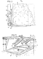
- the device shown in the figures mainly comprises a framework 1 provided on the underside with a carrying element 2 formed, for example, by a fork and on the top side with a guide 3, along which is guided a carriage 4 having a cutting member 5 adapted to move up and down in the direction of the arrow P1
- the framework 1 is movable up and down by means of a cylinder 6 along a frame 8 that can be coupled with an agricultural tractor 7.
- Fig. 2 is a perspective view of the lower part of the device of fig. 1; the corresponding parts are designated by the same reference numerals.
- a pressing member 15 is arranged above the carrying element 2, said member 15 being proviaea on tne unaersiae witn supports 16 extending across the carrying element (see also fig. 1).
- the pressing member 15 is fastened to the end of two coupling rods 17, 18 each of which is pivotally connected with two pivotal rods 19 and 20 respectively.
- the pivotal rods 19, 20 are each pivoted to the framework 1 in a manner such that a pivotal quadrangle is formed.
- a tensile spring 21 is arranged between the coupling rod 18 and one of the pivotal rods 19, 20.
- the pressing member 15 can be used as follows. By lowering the framework 1 along the guide 8 the supports 16 will touch the ground. While driving the tractor forwards, the supports 16 will remain on the ground, whilst the device is drawn on. Therefore, the pressing member 15 will perform a movement with respect to the carrying element 2 and will slip an ensilage slice S received on the carrying element 2 off said carrying element 2.
- the positions of the pivotal joints 17, 18, 19 and 20 are selected so that the rod-shaped pressing member 15 moves along a path substantially parallel to the top face of the carrying element 2, as a result of which the supports 16 continue extending across the tines of the carrying element 2 throughout the length of movement of the pressing member 15.
- the slice can be effectively slipped out of the device.
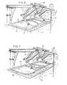
- Fig. 4 shows a similar rod system, but intended for a ram operating on the top side of an ensilage slice.
- the rod system comprises a coupling rod 25, the end of which is provided with the pushing ram 26.
- the coupling rod is connected with two pivotal rods 27 and 28, which is rotatably fastened to a support 29.
- the support 29 is held in place on the inner side of the guide rail 3 of the device.
- a hydraulic ram 30, operating between the support 29 and the ram 27, ensures an upward-downward movement of the pressing ram 26 in a manner such that this movement is substantially rectilinear.
- Figs. 5, 6 and 7 are perspective views of different embodiments of the rams to be used.
- Figs. 5, 6 and 7 show a ram in the form of a curved tubing 32, which is omnidirectionally pivoted at 32 to the coupling rod 25 of the rod system.
- the shape of the ram 31 substantially matches the cut of the cutting member 5 in the silo S.
- each ram has its own rod system and its own hydraulic ram 30.
- Fig. 6 shows an embodiment in which the pivotal rods 27 of two systems have arranged between them a more or less resilient coupling rod 33, which is engaged by a common hydraulic ram 30.
- the two rams 31 simultaneously move upwards or downwards.
- an omnidirectionally pivotable joint may be arranged between the rod 33 and the hydraulic ram 30 and the pivotal rods 27 respectively instead of using a resilient rod 33.
- Fig. 7 shows an embodiment in which the rod system having a common hydraulic ram corresponds with that of-fig. 6, though the pushing ram is constructed in the form of two parallel rods 34, 35 between which a leaf spring 36 is arranged.
- a leaf spring enhances the pushing effect of the ram on the top side of the ensilage.
Landscapes
- Life Sciences & Earth Sciences (AREA)
- Environmental Sciences (AREA)
- Shearing Machines (AREA)
- Nonmetal Cutting Devices (AREA)
- Processing Of Stones Or Stones Resemblance Materials (AREA)
Applications Claiming Priority (2)
| Application Number | Priority Date | Filing Date | Title |
|---|---|---|---|
| NL8101629 | 1981-04-01 | ||
| NL8101629A NL8101629A (nl) | 1981-04-01 | 1981-04-01 | Kuilvoersnijinrichting. |
Related Parent Applications (2)
| Application Number | Title | Priority Date | Filing Date |
|---|---|---|---|
| EP82200405A Division EP0062384A1 (fr) | 1981-04-01 | 1982-03-31 | Dispositif pour découper un bloc d'ensilage |
| EP82200405.7 Division | 1982-03-31 |
Publications (2)
| Publication Number | Publication Date |
|---|---|
| EP0139338A2 true EP0139338A2 (fr) | 1985-05-02 |
| EP0139338A3 EP0139338A3 (fr) | 1985-11-27 |
Family
ID=19837274
Family Applications (2)
| Application Number | Title | Priority Date | Filing Date |
|---|---|---|---|
| EP82200405A Ceased EP0062384A1 (fr) | 1981-04-01 | 1982-03-31 | Dispositif pour découper un bloc d'ensilage |
| EP84201520A Withdrawn EP0139338A3 (fr) | 1981-04-01 | 1982-03-31 | Désileuse à couteau |
Family Applications Before (1)
| Application Number | Title | Priority Date | Filing Date |
|---|---|---|---|
| EP82200405A Ceased EP0062384A1 (fr) | 1981-04-01 | 1982-03-31 | Dispositif pour découper un bloc d'ensilage |
Country Status (3)
| Country | Link |
|---|---|
| EP (2) | EP0062384A1 (fr) |
| DK (1) | DK146282A (fr) |
| NL (1) | NL8101629A (fr) |
Families Citing this family (1)
| Publication number | Priority date | Publication date | Assignee | Title |
|---|---|---|---|---|
| CN112753391A (zh) * | 2021-01-04 | 2021-05-07 | 刘怀丹 | 一种青贮料切割搬运装置 |
Citations (5)
| Publication number | Priority date | Publication date | Assignee | Title |
|---|---|---|---|---|
| FR2124224A1 (fr) * | 1971-02-02 | 1972-09-22 | Strautmann Bernhard Sohn | |
| FR2170276A1 (fr) * | 1972-02-04 | 1973-09-14 | Strautmann Et Sohne Bernhard | |
| DE2817901A1 (de) * | 1978-04-24 | 1979-10-25 | Duecker Gerhard Landmasch | Geraet zum entnehmen von futterportionen aus silos |
| DE2817433A1 (de) * | 1978-04-21 | 1979-10-31 | Krone Bernhard Gmbh Maschf | Fahrsilo-entnahmegeraet |
| FR2456464A1 (fr) * | 1979-05-18 | 1980-12-12 | Trioliet Silo Europ | Dispositif pour decouper et transporter un bloc d'ensilage et chassis presseur pour ce dispositif |
Family Cites Families (3)
| Publication number | Priority date | Publication date | Assignee | Title |
|---|---|---|---|---|
| US3780436A (en) * | 1971-05-24 | 1973-12-25 | Utica Cutlery Co | Device to cut or separate masses of frozen food |
| US4131996A (en) * | 1977-06-27 | 1979-01-02 | Janke William R | Blade for cutting wallboard |
| DE2929782C2 (de) * | 1979-02-21 | 1982-04-29 | Trioliet-Mullos Silo Nederland B.V., Losser | Vorrichtung zum Ausschneiden und Transportieren eines Gärfutterblockes |
-
1981
- 1981-04-01 NL NL8101629A patent/NL8101629A/nl not_active Application Discontinuation
-
1982
- 1982-03-31 EP EP82200405A patent/EP0062384A1/fr not_active Ceased
- 1982-03-31 EP EP84201520A patent/EP0139338A3/fr not_active Withdrawn
- 1982-03-31 DK DK146282A patent/DK146282A/da not_active Application Discontinuation
Patent Citations (5)
| Publication number | Priority date | Publication date | Assignee | Title |
|---|---|---|---|---|
| FR2124224A1 (fr) * | 1971-02-02 | 1972-09-22 | Strautmann Bernhard Sohn | |
| FR2170276A1 (fr) * | 1972-02-04 | 1973-09-14 | Strautmann Et Sohne Bernhard | |
| DE2817433A1 (de) * | 1978-04-21 | 1979-10-31 | Krone Bernhard Gmbh Maschf | Fahrsilo-entnahmegeraet |
| DE2817901A1 (de) * | 1978-04-24 | 1979-10-25 | Duecker Gerhard Landmasch | Geraet zum entnehmen von futterportionen aus silos |
| FR2456464A1 (fr) * | 1979-05-18 | 1980-12-12 | Trioliet Silo Europ | Dispositif pour decouper et transporter un bloc d'ensilage et chassis presseur pour ce dispositif |
Also Published As
| Publication number | Publication date |
|---|---|
| NL8101629A (nl) | 1982-11-01 |
| EP0062384A1 (fr) | 1982-10-13 |
| EP0139338A3 (fr) | 1985-11-27 |
| DK146282A (da) | 1982-10-02 |
Similar Documents
| Publication | Publication Date | Title |
|---|---|---|
| US5052098A (en) | Means for removing wires from bales in particular waste paper bales | |
| EP0091558A3 (fr) | Guide à réglage automatique pour machine à scier | |
| WO2004085115B1 (fr) | Machine pour grouper des produits tels que de l’herbe | |
| PT898877E (pt) | Dispositivo para o desfolhamento de videiras | |
| EP0139338A2 (fr) | Désileuse à couteau | |
| US4341354A (en) | Device for cutting out and transporting a silage block | |
| US4246816A (en) | Sheet cutting apparatus | |
| SE8201312L (sv) | Skogsavverkningsmaskin | |
| US3705481A (en) | Sugar cane topper for v-cutter harvester | |
| US4153087A (en) | Accumulator mechanism for tree harvesting apparatus | |
| FR2824699B1 (fr) | "machine pour le ramassage automatique des asperges" | |
| ES8205143A1 (es) | Perfeccionamientos en una cizalla para cortar material en forma de barra. | |
| US3856090A (en) | Sod cutter blade mounting | |
| WO1993018640A1 (fr) | Appareil permettant de decouper des balles | |
| US3529640A (en) | Tree harvesting and processing devices | |
| GB1569077A (en) | Device for slicing a block of cheese and the like | |
| JP2010104312A (ja) | 乗用型茶樹摘採機 | |
| US3530911A (en) | Mounting for shear | |
| US4455906A (en) | Gate shears | |
| EP0135228A1 (fr) | Procédé et appareil pour la récolte des champignons | |
| IE38932B1 (en) | Silage-cutting apparatus | |
| SU1140717A1 (ru) | Устройство дл обрезки веток и сучьев | |
| JPS6040105Y2 (ja) | コンバインにおける穀稈案内杆支持装置 | |
| GB2176684B (en) | Mowing apparatus | |
| GB1495537A (en) | Device for removing ensilage from trench silos |
Legal Events
| Date | Code | Title | Description |
|---|---|---|---|
| PUAI | Public reference made under article 153(3) epc to a published international application that has entered the european phase |
Free format text: ORIGINAL CODE: 0009012 |
|
| AC | Divisional application: reference to earlier application |
Ref document number: 62384 Country of ref document: EP |
|
| AK | Designated contracting states |
Designated state(s): BE DE FR GB NL |
|
| PUAL | Search report despatched |
Free format text: ORIGINAL CODE: 0009013 |
|
| AK | Designated contracting states |
Designated state(s): BE DE FR GB NL |
|
| STAA | Information on the status of an ep patent application or granted ep patent |
Free format text: STATUS: THE APPLICATION IS DEEMED TO BE WITHDRAWN |
|
| 18D | Application deemed to be withdrawn |
Effective date: 19860728 |
|
| RIN1 | Information on inventor provided before grant (corrected) |
Inventor name: PRINS, NICOLAAS Inventor name: WESTSTRATE, MARINUS Inventor name: VISSERS, HERMANUS HENDRIK |