EP0137432B1 - Form creating system - Google Patents
Form creating system Download PDFInfo
- Publication number
- EP0137432B1 EP0137432B1 EP84111629A EP84111629A EP0137432B1 EP 0137432 B1 EP0137432 B1 EP 0137432B1 EP 84111629 A EP84111629 A EP 84111629A EP 84111629 A EP84111629 A EP 84111629A EP 0137432 B1 EP0137432 B1 EP 0137432B1
- Authority
- EP
- European Patent Office
- Prior art keywords
- point
- line
- triangle
- points
- straight line
- Prior art date
- Legal status (The legal status is an assumption and is not a legal conclusion. Google has not performed a legal analysis and makes no representation as to the accuracy of the status listed.)
- Expired - Lifetime
Links
Images


Classifications
-
- G—PHYSICS
- G06—COMPUTING OR CALCULATING; COUNTING
- G06T—IMAGE DATA PROCESSING OR GENERATION, IN GENERAL
- G06T11/00—Two-dimensional [2D] image generation
-
- G—PHYSICS
- G05—CONTROLLING; REGULATING
- G05B—CONTROL OR REGULATING SYSTEMS IN GENERAL; FUNCTIONAL ELEMENTS OF SUCH SYSTEMS; MONITORING OR TESTING ARRANGEMENTS FOR SUCH SYSTEMS OR ELEMENTS
- G05B2219/00—Program-control systems
- G05B2219/30—Nc systems
- G05B2219/36—Nc in input of data, input key till input tape
- G05B2219/36372—Light, magnetic pen
Definitions
- the present invention relates to a form creating system, i.e. to an improved and advanced system which is capable of creating a desired form or modifying its created form in the field of CAD (Computer Aided Design) and/or CAM (Computer Aided Manufacturing), NC machine tool, computer graphics, computer vision and the like.
- CAD Computer Aided Design
- CAM Computer Aided Manufacturing
- CAD/CAM computer vision or the like
- three types of modellings to express a desired or predetermined form that is, a wire frame modeller, a surface modeller, and a solid modeller.
- the above kinds of forms can be expressed by using constracted points which are roughly populated as a finite type of a set which has lower density.
- these forms can be also expressed by the same type of a set which has higher density.
- the two modellers of the above type can be performed by the way of estimating the lacked points among the given points obtained so as to express the form, that is by means of interpolation operation based on the functional approximation.
- the solid modeller piles up simple or primitive forms obtained as the typical sets in which the points are densly populated in a manner similar to a building-blocks-work to express a predetermined form.
- Each of these three conventional methods features a function to express forms for solid bodies.
- the Article "A New Method for Vector Generation” by R.L.T. Cederberg from Computer Graphics and Image Processing, Vol. 9, pages 183-195 (1979) describes a method of approximating a straight line between two fixed points.
- the straight line is approximated by a series of short vectors, whereby the first and last vectors pass through the first and second fixed points respectively.
- the vectors are determined so that they are centred to the straight line i.e. they straddle the straight line uniformly.
- the disadvantage of this approach for operating an NC machine is that the zig-zag nature of the approximated line results in the NC tool being driven in along a zig-zag path rather than along a smooth line or around a smooth curve.
- a two-dimensional or three-dimensional form creating system comprising: a reference point setting means for setting a position of a point in a formative space, said reference point setting means setting each position of both a first point and a second point at arbitary but different positions, each said position being a constructive point lying on a contour of a forming solid or figure a reference line setting means for setting a reference straight line passing through said reference point, said reference line setting means setting a first and second straight line passing separately through said first point and said second point respectively, input means for determining the position of a plurality of intermediate reference points, which lie on a contour of said solid or figure between the first and second points, characterized by said reference line setting means setting said first and second straight lines in arbitrary directions but not parallel to each other; triangle form setting means for setting a triangular wire frame-like form which is formed by a constructive procedure in accordance with both the position of said second point and the direction of said second line as well as both the position of said first point and the direction of said
- Fig. 1 a general view of a system or a first embodiment of the invention is illustrated.
- the illustrated embodiment is provided with keyboard 1 and light pen 2 which cooperate to input positional information on a point that corresponds to the end of a form to be created, that is, the first point of the form to be created. It also incorporates an operation circuit 3 to perform a predetermined operation in accordance with input signals from input means such as keyboard 1 and light pen 2. It further includes a display unit to display the thus-created forms, a printer 5 to print such forms, and an external memory unit 6 which stores such forms in the form of predetermined signals such as magnetic signals or light signals.
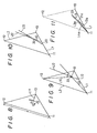
- Figs. 2 through 22 illustrate principles of the invention that are useful in creating a desired form and, in particular, Fig. 2 to 11 show the principles of the invention that can be used to obtain two-dimensional forms.
- heavy lines are used to express lines that are newly found in the respective figures.
- Fig. 2 there is shown the first setting step necessary to create a form.
- a first point 11 and a second point 12 both of which are set at their aribitrary but different positions respectively, as well as a first straight line L1 passing through the first point 11 and a second straight line L2 passing through the second point 12. All of these points and lines are present in the same plane, so that a desired form can be produced between these two points.
- light pen 2 may be placed at an aribitrary position on the display unit 4 to set the first point 11.
- the second point 12 can be established at an aribitrary position other than that of the first point 11.
- a straight line passing through the first point 11, or L1 is set, with its direction being determined by means of keyboard 1.
- a straight line passing through the second point 12, or L2 is set, with its direction determined by keyboard 1.
- a point where both lines L1 and L2 intersect with each other is set as an intersection point 13.
- Fig. 3 illustrates a fundamental triangle and an isosceles triangle both formed from the setting shown in Fig. 2.
- First and second points 11 and 12 are connected to draw a line segment, which is denoted by L3 and called a chord.
- L3 is called a chord
- the reason this line L3 is called a chord is that, when a part (a contour line) of a desired form is to be created between first and second points 11 and 12, if such contour line is considered as a circular arc, then line L3 corresponds to a chord thereof.
- a triangle enclosed by three lines L1, L2 and L3 is here called a fundamental triangle. In this case, a shorter one of the two sides other than the side formed by chord L3, among the three sides of this fundamental triangle, is one formed by line L1. This shorter side is a line segment connecting points 11 and 13.
- an isosceles triangle having two equilateral sides each equal to the above-mentioned shorter side is so formed as to be superposed on the fundamental triangle.
- a new point which is equi-distant from intersection point 13 as with line L1 is set on line L2.
- This new point is represented by 21.
- the other of the equilateral sides of this isosceles triangle is a line segment connecting point 21 and intersection point 13 in Fig. 2.
- a line segment between first point 11 and new point 21 is called L4.
- Fig. 4 illustrates how to determine a constant ⁇ necessary to find a third point constituting a part of a form to be created.
- a straight line bisecting an internal angle of an isosceles triangle at point 11 is denoted as L5, and such internal angle is denoted as ⁇ (13)(11)(21).
- ⁇ (13)(11)(21) expresses an angle included by a line segment between points 13 and 11, and a line segment between points 11 and 21. This way of expression on angles will be employed hereinafter as well.
- ⁇ ⁇ area of ⁇ (21)(11)(13) ⁇ / ⁇ area of ⁇ (12)(11)(22) ⁇
- ⁇ (21)(11)(13) denotes a triangle enclosed by points 21, 11 and 13. Also, this way of expression on triangles will be employed hereinafter as well.
- Fig. 5 illustrates how to find an incenter of the above-mentioned isosceles triangle.
- an incenter of a triangle is a point of bisectors of its respective internal angles and the three bisectors intersect at one point.
- a bisector of the internal angle of the isosceles triangle at point 21 is denoted by L6.
- a point of intersection of the two bisectors L5 and L6, or, the incenter of the isosceles triangle is represented by 23.
- a middle point between point 11 and incenter 23 is denoted as 24 and a middle point between point 21 and incenter 23 is denoted as 25.
- Fig. 6 illustrates how to find an incenter of the above-mentioned fundamental triangle.
- a bisector of the internal angle of the fundamental triangle at point 11 is represented by a straight line L7; a bisector of the same at point 12 by a straight line L8; and, an intersection point of the two bisectors L7 and L8 or the incenter of the fundamental triangle by point 14.
- Fig. 7 illustrates how to decide an unequilibrium amount S. Not only the parameter ⁇ but also a parameter ⁇ is necessary to find a third point constituting a part of the form to be created. To obtain this parameter ⁇ , it is necessary to decide the unequilibrium amount S, which depends on the difference between the attributes of the fundamental and isosceles triangles.
- Fig. 8 illustrates how to obtain a distance d between the internal center 14 of the fundamental triangle and a third point to be found now.
- Figs. 9 and 10 illustrate how to find a third straight line L13 at the third point 33.
- line L13 is a tangent to a form outline at point 33.
- a tangent to the outline at point 33 is the third straight line L13.
- line L13 is a straight line required to produce a new third point between points 33 and 11. This third straight line is found as follows:
- a straight line passing through both points 11 and 33 be L9
- a straight line passing through both points 12 and 33 be L10
- a bisector of the intersectional angle of lines L10 and L9 be L12.
- This bisector L12 is shown in Fig. 9.
- the thus-obtained straight line is the third straight line L13. If the operation described in Figs. 2 through 8 is executed using this third straight line L13, then the position of a new third point can be found.
- Fig. 11 illustrates how to find a new third point in the above-mentioned manner.
- Fig. 12 illustrates how the form can be modified when only the directions of lines L1 and L2 out of all the parameters are changed.
- form C has been created by considering the first and second straight lines as L1 and L2 respectively in accordance with the above -described technique. (Of course, this form C may be considered as an outline of a desired form, not as the desired form itself.)
- the form C is altered into a form represented by a two-dot chained line Cb.
- the feature of the form modified through change of the directions of the first and second lines L1 and L2 is that its convex portions are respectively shifted upwardly and downwardly with respect to the bisector L11.
- both lines L1 and L2 must not be parallel to each other after they have been respectively rotated. This is necessary to ensure that the form created has not inflection point at point 11 or 12. Therefore, when the form created may have an inflection point at either of point 11 or 12, no special restrictions are required on the rotational conditions between lines L1 and L2.
- Fig. 13 illustrates how a form can be modified when only the position control parameter ⁇ is changed.
- Change of the position control parameter ⁇ causes the degree of expansion of the entire form or the curvature of the form to vary.
- Fig. 13 there is shown the change of the form which occurs when the position control parameter ⁇ is changed to a negative value after it is set as a positive value and the form C is once created.
- Form Cc which is obtained after the parameter ⁇ is changed to a negative value, has a smaller degree of expansion than that of the form C and comes nearer the chord L3.
- position control parameter ⁇ if the position control parameter ⁇ is set as 0, then the form passes through the incenter 14 of the fundamental triangle. If the parameter ⁇ is set as a positive value, then the form expands out away from the internal center 14 to come closer to intersection point 13; the greater the parameter ⁇ , the closer the form comes to intersection point 13. Conversely, if the parameter is changed to a negative value, then the form contracts away from internal center 14 and approaches the chord L3; the greater the absolute value of the parameter, the closer it approaches chord L3, which means that the form C comes closer to a straight line.
- position included in "position control parameter” means a position at which the form to be created intersects with bisector L11. Thus, to change the position control parameter ⁇ means the change of this intersection point.
- the form is altered only in curvature. Also, when the form created prior to the change of the position control parameter ⁇ is contained within the fundamental triangle, even if the parameter is thereafter changed, the form created will not be bulged out of the fundamental triangle.
- Fig. 14 illustrates how a form can be changed when only the tangent control parameter ⁇ is varied.
- the degree of the expansion of the form can be changed between two points used to create a form (or to modify a created form)(that is, two points corresponding to the then first and second points).
- the form C is once created between the first and second points 11 and 12.
- the third straight line L13 is identical with a tangent to the form C at the third point 33.
- a new third point is decided between points 11 and 33 in accordance with the directions of this tangent L13 and line L1. In this way, the form is gradually determined or produced.
- tangent control parameter ⁇ is changed at point 33 to change line L13 into line L13d, for example, then a form being created is changed into one shown by a two-dot chained line Cd between points 33 and 11. That is, if line L13 is rotated clockwise by changing the tangent control parameter ⁇ , then a form being created is expanded out to the right in the drawing within the lower portion of bisector L11.
- the tangent control parameter is useful to enhance the degree of freedom of the operation for creating a form.
- the values of the above-mentioned position and tangent control parameters can be varied to create a form or modify a created form not only between points 33 and 11 or 33 and 12, but also between every point and any other point in the form C.
- Fig. 15 illustrates a principle to find a third straight line in a simple manner.
- the above-mentioned manner is usually used to create or modify a planar form.
- This manner can also be applied in creating or modifying a three-dimensional form. Specifically, the above manner is used to create a plurality of planar forms and then these planar forms are superposed on each other to produce a three-dimension form in the form of a so-called flexible wire frame or network.
- the three-dimensional form is not directly created, but a plurality of outlines or three-dimensional outlines of the form are first obtained and then these outlines are connected successively to create the desired form.
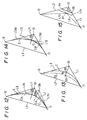
- Fig. 16 there are set a first point 51, a second point 52, a first straight line L51, and a second straight line L52.
- L51 is a line that passes through point 51
- L52 is a line that passes through point 52.
- Points 51 and 52 are interconnected to produce a chord 50. Why this line segment connecting these two points is expressed as a chord is the same reason as has been described in connection with Fig. 3.
- the extensions of the lines L51 and L52 are considered not to intersect with each other. That is, a form to be created here is a three-dimensional one and thus outlines to be drawn between points 51 and 52, in many cases, do not exist in one plane. Also, L51 should be a tangent to the outline at point 51, and L52 should be a tangent to the outline at point 52. For this reason, in most cases, lines L51 and L52 do not intersect with each other.
- Fig. 17 illustrates an orthographic view of the first line L51 projected in a plane composed of the chord 50 and the second line L52.
- the orthographically-projected line of the line L51 be L53. That is, when light is applied to a plane formed by chord 50 and line L52, the resultant shadow of line L51 is considered as line L53.
- Fig. 18 illustrates an orthographic view of the second line L52 projected in a plane composed of the chord 50 and the first line L51.
- the orthographic line of the line L52 be L54. That is, when light is applied to a plane formed by chord 50 and line L51, the resultant shadow of the second line L52 is considered as line L54.
- Fig. 19 illustrates how to form a fundamental triangular pyramid. Specifically, points 53 and 54 are connected to produce a line segment. Let this line segment be L55. As a result of this, four planes enclosed by line L50, L51, L52, L53, L54 and L55 can be produced, which in turn cooperate to enclose or form a triangular pyramid. This is interpreted as a fundamental triangular pyramid.
- Fig. 20 illustrates how to form a temporary triangle ⁇ .
- a torsion control parameter is used to find a point 55 on line segment L55.
- the torsion control parameter ⁇ may be obtained as a ratio of angles.
- Fig. 21 illustrates how to form a fundamental triangle within the above-mentioned temporary triangle ⁇ .
- a triangle that is enclosed by line L50 and the thus-obtained lines L58 and L59 is a three-dimensional, fundamental triangle necessary for creation of a three-dimensional form.
- This three-dimensional fundamental triangle corresponds to the fundamental triangle formed in Fig. 3 to create the two-dimensional form.
- Fig. 22 illustrates how to form an isoseles triangle from the above-mentioned three-dimensional fundamental triangle.
- the above-mentioned fundamental triangle can be operated similarly to the triangle in Fig. 3.
- the same idea as employed in the previously described two-dimensional form creation can be applied. That is, if the same operations as in Figs. 2 to 10 are performed based on the three-dimensional fundamental triangle ⁇ (52)(51)(56) and isosceles triangle ⁇ (59)(51)(56), then three-dimensional third point 71 and third straight line L73 can be found.
- a torsion control auxiliary parameter ⁇ must used to create a three-dimensional form. Specifically, a tangent to an outline of a form to be created at point 71 has a certain angle relative line L73 within the plane of the three-dimensional fundamental triangle, and this certain angle is called the torsion control auxiliary parameter ⁇ . This parameter must be taken into consideration so as to obtain a three-dimensional form.
- Line L72 is a straight (tangent) line that is obtained as a result of consideration of the torsion auxiliary parameter ⁇ .
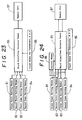
- FIG. 23 a block diagram of an embodiment of the invention is illustrated.
- This embodiment comprises a first point setting means 81 to set up a first point 11 at an aribitrary position as shown in Fig. 2, and a second point setting means 82 to set up a second point 12 at an arbitrary position different from that of point 11.
- a first straight line setting means 83 to set up a first line L1 passing through point 11 in an arbitrary direction
- a second straight line setting means 84 to set up a second line L2 passing through point 12 in an arbitrary direction.
- these setting means 81 - include input means such as keyboard 1 and light pen 2. As its principle is shown in Figs.
- a third point/straight line decision means 85 which, in accordance with the positions of points 11 and 12 as well as the directions of lines L1 and L2, decides the position of a third point 33 and the direction of a third straight line L13 containing this third point 33.
- An operation circuit 3 serves as the third point/straight line decision means 85.
- Third point/straight line decision means 85 is also provided with input means 86 for input of the parameters ⁇ , ⁇ , ⁇ , ⁇ , and the like. Keyboard 1 may be used as this input means 86. There is further provided a memory unit 87 which stores information on each point decided by the decision means 85.
- the embodiment in Fig. 23 is constructed such that, as a first step, it can find a third point from the first and second points 11 and 12 as well as the first and second lines L1 and L2.
- Fig. 24 illustrates a block diagram of another embodiment of the invention.
- This embodiment is provided with a control means 38 which controls each of means 81 - 84 repetitively, in accordance with previously set or decided points and directions of lines at such points as well as a new point decided by the decision means 85 and direction of a new line at this new point, to provide a large number of points between the first and second points 11 and 12.
- This control means 83 can be operated by the same principle as explained in connection with Fig. 11.
- Fig. 25 illustrates a block diagram of still another embodiment of the invention, especially used to create a two-dimensional form.
- a first point setting means 81 to set up a first point 11 at an arbitrary position, with its principle being illustrated in Fig. 2, and a second point setting means 82 to set up a second point 12 at a different arbitrary position from that of the first point 11.
- This embodiment also includes a first straight line setting means 83 to establish a first straight line L1 passing through point 11 in an arbitrary direction and a two-dimensional second straight line setting means 91 to establish a second straight line L2 passing through point 12 in an arbitrary direction within a plane formed by point 11 and line L1.
- an isosceles triangle forming means 92 In this forming means 92, at first a fundamental triangle is formed by a chord L3 between points 11 and 12, the first line L1 and the second line L2, and then an isosceles triangle having two equal sides each of which is equal to the shorter one of the fundamental triangle sides other than the side formed by the chord L3.
- this embodiment includes a third point operation means 93 which, as its principle is illustrated in Figs. 5 through 11 and 15, calculates the position of a third point as well as the direction of a third line containing this third point in accordance with the attributes of the above-mentioned fundamental and isosceles triangles.
- this third point operation means 93 comprises the following components: that is, an internal center position operation means 93a (which applies the principles in Figs. 5 and 6) to calculate the positions of the incenters of the fundamental and isosceles triangles; a first triangle area operation means 93b (which applies the principle in Fig.
- Third point operation means 93 further includes means for inputting the parameters ⁇ , ⁇ , ⁇ , ⁇ and a memory unit 87 to store information on each of points decided by the third point operation means 93 itself.
- Operation circuit 3 is adapted to be capable of performing functions of the above-mentioned fundamental and isosceles triangles forming means 92 as well as those of the third point operation means 93.
- the present invention is capable of creating a form or modifying a created form with ease.
- the invention can be effectively applied to a shape working machine, a form recognition device, an image processor, an auto-drawing instrument, an image creator and the like in NC machine tools or the like.
- the invention can perform not only two-dimensional operations but also three-dimensional operations.
- the present invention provides a single form creating system which provides for free access to a form to be created throughout the whole process ranging from its design step to its manufacturing step.
Landscapes
- Physics & Mathematics (AREA)
- General Physics & Mathematics (AREA)
- Engineering & Computer Science (AREA)
- Theoretical Computer Science (AREA)
- Processing Or Creating Images (AREA)
- Moulds For Moulding Plastics Or The Like (AREA)
- Numerical Control (AREA)
- Mounting, Exchange, And Manufacturing Of Dies (AREA)
- Molds, Cores, And Manufacturing Methods Thereof (AREA)
- Preparation Of Compounds By Using Micro-Organisms (AREA)
- Diaphragms For Electromechanical Transducers (AREA)
- Multi-Process Working Machines And Systems (AREA)
Priority Applications (1)
| Application Number | Priority Date | Filing Date | Title |
|---|---|---|---|
| AT84111629T ATE71230T1 (de) | 1983-09-30 | 1984-09-28 | Formerzeugungssystem. |
Applications Claiming Priority (2)
| Application Number | Priority Date | Filing Date | Title |
|---|---|---|---|
| JP58182495A JPS6074003A (ja) | 1983-09-30 | 1983-09-30 | 形状創成装置 |
| JP182495/83 | 1983-09-30 |
Publications (3)
| Publication Number | Publication Date |
|---|---|
| EP0137432A2 EP0137432A2 (en) | 1985-04-17 |
| EP0137432A3 EP0137432A3 (en) | 1986-01-22 |
| EP0137432B1 true EP0137432B1 (en) | 1992-01-02 |
Family
ID=16119283
Family Applications (1)
| Application Number | Title | Priority Date | Filing Date |
|---|---|---|---|
| EP84111629A Expired - Lifetime EP0137432B1 (en) | 1983-09-30 | 1984-09-28 | Form creating system |
Country Status (5)
| Country | Link |
|---|---|
| US (1) | US4864520A (enExample) |
| EP (1) | EP0137432B1 (enExample) |
| JP (1) | JPS6074003A (enExample) |
| AT (1) | ATE71230T1 (enExample) |
| DE (1) | DE3485406D1 (enExample) |
Families Citing this family (61)
| Publication number | Priority date | Publication date | Assignee | Title |
|---|---|---|---|---|
| JP2630605B2 (ja) * | 1987-07-29 | 1997-07-16 | 三菱電機株式会社 | 曲面創成方法 |
| US5140672A (en) * | 1988-02-23 | 1992-08-18 | Nec Corporation | Diagram generator having reference table which included reproducing and name assigning units for expanding circuit from lower to higher level |
| US5070534A (en) * | 1988-10-17 | 1991-12-03 | International Business Machines Corporation | Simplified cad parametric macroinstruction capability including variational geometrics feature |
| EP0382495B1 (en) * | 1989-02-08 | 2000-04-26 | Canon Kabushiki Kaisha | Figure processing apparatus |
| JPH02257309A (ja) * | 1989-03-30 | 1990-10-18 | Fanuc Ltd | Ncプログラムの描画方法 |
| US5838328A (en) * | 1989-05-19 | 1998-11-17 | Hewlett-Packard Company | Method for generating graphical models and computer aided design system |
| US5713034A (en) * | 1990-08-07 | 1998-01-27 | Oki Electric Industry Co., Ltd. | CAE system for preparing transmission network and analyzing load in mechanical system |
| JP2796016B2 (ja) * | 1992-06-30 | 1998-09-10 | 本田技研工業株式会社 | Cadシステム |
| FR2693567B1 (fr) * | 1992-07-10 | 1994-10-14 | Caso | Procédé et dispositif de fabrication d'éléments adhésifs destinés à être appliqués sur une surface tridimensionnelle en vue de sa décoration. |
| US5636338A (en) * | 1993-01-29 | 1997-06-03 | Silicon Graphics, Inc. | Method for designing curved shapes for use by a computer |
| US5467293A (en) * | 1993-07-01 | 1995-11-14 | Electronic Data Systems Corporation | System and method for associative solid sectioning during drafting of geometric models |
| US5649079A (en) * | 1994-02-28 | 1997-07-15 | Holmes; David I. | Computerized method using isosceles triangles for generating surface points |
| US5594852A (en) * | 1994-08-17 | 1997-01-14 | Laser Products, Inc. | Method for operating a curve forming device |
| US6014148A (en) * | 1994-08-17 | 2000-01-11 | Laser Products, Inc. | Method for generating two dimensional and three dimensional smooth curves and for driving curve forming devices |
| JPH09212675A (ja) * | 1996-02-06 | 1997-08-15 | Unix Soft:Kk | Cad装置 |
| US6441822B1 (en) * | 1999-04-02 | 2002-08-27 | Bruce H. Johnson | Drawing with circular arcs |
| US7620527B1 (en) | 1999-05-10 | 2009-11-17 | Johan Leo Alfons Gielis | Method and apparatus for synthesizing and analyzing patterns utilizing novel “super-formula” operator |
| JP4068319B2 (ja) * | 2001-09-19 | 2008-03-26 | 株式会社小糸製作所 | 車両用灯具の反射鏡の反射面設計方法 |
| JP2003162907A (ja) * | 2001-11-27 | 2003-06-06 | Koito Mfg Co Ltd | 反射面設計システム、反射面設計方法、記録媒体、及びコンピュータプログラム |
| DE102005050209A1 (de) * | 2005-10-20 | 2007-04-26 | Ott, Reinhold, Waterloo | Vorrichtung zur Einspeisung eines Videosignals in eine Anzeigevorrichtung und Betriebsverfahren hierfür |
| DE102005050205A1 (de) * | 2005-10-20 | 2007-04-26 | Mtu Aero Engines Gmbh | Verfahren und Vorrichtung zum Kompensieren von Lage-und Formabweichungen |
| US9417754B2 (en) | 2011-08-05 | 2016-08-16 | P4tents1, LLC | User interface system, method, and computer program product |
| CN104487930A (zh) | 2012-05-09 | 2015-04-01 | 苹果公司 | 用于移动和放置用户界面对象的设备、方法和图形用户界面 |
| WO2013169843A1 (en) | 2012-05-09 | 2013-11-14 | Yknots Industries Llc | Device, method, and graphical user interface for manipulating framed graphical objects |
| WO2013169865A2 (en) | 2012-05-09 | 2013-11-14 | Yknots Industries Llc | Device, method, and graphical user interface for moving a user interface object based on an intensity of a press input |
| EP2847659B1 (en) | 2012-05-09 | 2019-09-04 | Apple Inc. | Device, method, and graphical user interface for transitioning between display states in response to a gesture |
| CN104508618B (zh) | 2012-05-09 | 2018-01-05 | 苹果公司 | 用于针对在用户界面中执行的操作提供触觉反馈的设备、方法和图形用户界面 |
| JP6031186B2 (ja) | 2012-05-09 | 2016-11-24 | アップル インコーポレイテッド | ユーザインタフェースオブジェクトを選択するためのデバイス、方法及びグラフィカルユーザインタフェース |
| WO2013169846A1 (en) | 2012-05-09 | 2013-11-14 | Yknots Industries Llc | Device, method, and graphical user interface for displaying additional information in response to a user contact |
| WO2013169875A2 (en) | 2012-05-09 | 2013-11-14 | Yknots Industries Llc | Device, method, and graphical user interface for displaying content associated with a corresponding affordance |
| WO2013169845A1 (en) | 2012-05-09 | 2013-11-14 | Yknots Industries Llc | Device, method, and graphical user interface for scrolling nested regions |
| EP2847662B1 (en) | 2012-05-09 | 2020-02-19 | Apple Inc. | Device, method, and graphical user interface for providing feedback for changing activation states of a user interface object |
| WO2013169851A2 (en) | 2012-05-09 | 2013-11-14 | Yknots Industries Llc | Device, method, and graphical user interface for facilitating user interaction with controls in a user interface |
| WO2013169849A2 (en) | 2012-05-09 | 2013-11-14 | Industries Llc Yknots | Device, method, and graphical user interface for displaying user interface objects corresponding to an application |
| WO2013169842A2 (en) | 2012-05-09 | 2013-11-14 | Yknots Industries Llc | Device, method, and graphical user interface for selecting object within a group of objects |
| CA2885954A1 (en) | 2012-09-24 | 2014-03-27 | The Antenna Company International N.V. | Lens antenna, method of manufacturing and using such an antenna, and antenna system |
| AU2013368443B2 (en) | 2012-12-29 | 2016-03-24 | Apple Inc. | Device, method, and graphical user interface for transitioning between touch input to display output relationships |
| WO2014105279A1 (en) | 2012-12-29 | 2014-07-03 | Yknots Industries Llc | Device, method, and graphical user interface for switching between user interfaces |
| WO2014105274A1 (en) | 2012-12-29 | 2014-07-03 | Yknots Industries Llc | Device, method, and graphical user interface for navigating user interface hierarchies |
| CN107831991B (zh) | 2012-12-29 | 2020-11-27 | 苹果公司 | 用于确定是滚动还是选择内容的设备、方法和图形用户界面 |
| AU2013368441B2 (en) | 2012-12-29 | 2016-04-14 | Apple Inc. | Device, method, and graphical user interface for forgoing generation of tactile output for a multi-contact gesture |
| HK1215094A1 (zh) | 2012-12-29 | 2016-08-12 | Apple Inc. | 用於根據具有模擬三維特徵的控制圖標的外觀變化來移動光標的設備、方法和圖形用戶界面 |
| WO2015147635A1 (en) | 2014-03-26 | 2015-10-01 | The Antenna Company International N.V. | Patch antenna, method of manufacturing and using such an antenna, and antenna system |
| CN105446350B (zh) * | 2014-09-26 | 2018-05-29 | 科沃斯机器人股份有限公司 | 自移动机器人移动界限划定方法 |
| US9645732B2 (en) | 2015-03-08 | 2017-05-09 | Apple Inc. | Devices, methods, and graphical user interfaces for displaying and using menus |
| US9990107B2 (en) | 2015-03-08 | 2018-06-05 | Apple Inc. | Devices, methods, and graphical user interfaces for displaying and using menus |
| US10095396B2 (en) | 2015-03-08 | 2018-10-09 | Apple Inc. | Devices, methods, and graphical user interfaces for interacting with a control object while dragging another object |
| US10048757B2 (en) | 2015-03-08 | 2018-08-14 | Apple Inc. | Devices and methods for controlling media presentation |
| US9632664B2 (en) | 2015-03-08 | 2017-04-25 | Apple Inc. | Devices, methods, and graphical user interfaces for manipulating user interface objects with visual and/or haptic feedback |
| US9639184B2 (en) | 2015-03-19 | 2017-05-02 | Apple Inc. | Touch input cursor manipulation |
| US10152208B2 (en) | 2015-04-01 | 2018-12-11 | Apple Inc. | Devices and methods for processing touch inputs based on their intensities |
| US20170045981A1 (en) | 2015-08-10 | 2017-02-16 | Apple Inc. | Devices and Methods for Processing Touch Inputs Based on Their Intensities |
| US9860451B2 (en) | 2015-06-07 | 2018-01-02 | Apple Inc. | Devices and methods for capturing and interacting with enhanced digital images |
| US9830048B2 (en) | 2015-06-07 | 2017-11-28 | Apple Inc. | Devices and methods for processing touch inputs with instructions in a web page |
| US10200598B2 (en) | 2015-06-07 | 2019-02-05 | Apple Inc. | Devices and methods for capturing and interacting with enhanced digital images |
| US10346030B2 (en) | 2015-06-07 | 2019-07-09 | Apple Inc. | Devices and methods for navigating between user interfaces |
| US9891811B2 (en) | 2015-06-07 | 2018-02-13 | Apple Inc. | Devices and methods for navigating between user interfaces |
| US10416800B2 (en) | 2015-08-10 | 2019-09-17 | Apple Inc. | Devices, methods, and graphical user interfaces for adjusting user interface objects |
| US9880735B2 (en) | 2015-08-10 | 2018-01-30 | Apple Inc. | Devices, methods, and graphical user interfaces for manipulating user interface objects with visual and/or haptic feedback |
| US10248308B2 (en) | 2015-08-10 | 2019-04-02 | Apple Inc. | Devices, methods, and graphical user interfaces for manipulating user interfaces with physical gestures |
| US10235035B2 (en) | 2015-08-10 | 2019-03-19 | Apple Inc. | Devices, methods, and graphical user interfaces for content navigation and manipulation |
Family Cites Families (14)
| Publication number | Priority date | Publication date | Assignee | Title |
|---|---|---|---|---|
| US1661096A (en) * | 1927-05-09 | 1928-02-28 | Rowe Joseph Eugene | Mathematical instrument |
| US3872462A (en) * | 1955-06-14 | 1975-03-18 | Jerome H Lemelson | Form filling system and method |
| FR1390164A (fr) * | 1962-12-03 | 1965-02-26 | Renault | Procédé de génération d'une courbe et dispositif pour la mise en oeuvre de ce procédé |
| US3996673A (en) * | 1975-05-29 | 1976-12-14 | Mcdonnell Douglas Corporation | Image generating means |
| JPS5588129A (en) * | 1978-12-27 | 1980-07-03 | Fuji Photo Film Co Ltd | Form synthesizer-recorder |
| US4246580A (en) * | 1979-04-25 | 1981-01-20 | Eaton Corporation | Image processing for bistatic image radar |
| US4325065A (en) * | 1979-08-09 | 1982-04-13 | Eaton Corporation | Bistatic imaging radar processing for independent transmitter and receiver flightpaths |
| EP0052684B1 (en) * | 1980-11-26 | 1985-09-04 | International Business Machines Corporation | A method of testing a display apparatus |
| JPS57122441A (en) * | 1981-01-22 | 1982-07-30 | Toppan Printing Co Ltd | Screen for gravure and its production |
| JPS5872242A (ja) * | 1981-10-23 | 1983-04-30 | Fujitsu Ltd | 円孤表示方式 |
| US4507656A (en) * | 1982-09-13 | 1985-03-26 | Rockwell International Corporation | Character/vector controller for stroke written CRT displays |
| US4535328A (en) * | 1982-09-13 | 1985-08-13 | Rockwell International Corporation | Digitally controlled vector generator for stroke written CRT displays |
| US4620287A (en) * | 1983-01-20 | 1986-10-28 | Dicomed Corporation | Method and apparatus for representation of a curve of uniform width |
| US4608653A (en) * | 1984-03-30 | 1986-08-26 | Ryozo Setoguchi | Form creating system |
-
1983
- 1983-09-30 JP JP58182495A patent/JPS6074003A/ja active Granted
-
1984
- 1984-09-28 EP EP84111629A patent/EP0137432B1/en not_active Expired - Lifetime
- 1984-09-28 AT AT84111629T patent/ATE71230T1/de not_active IP Right Cessation
- 1984-09-28 DE DE8484111629T patent/DE3485406D1/de not_active Expired - Lifetime
-
1987
- 1987-07-20 US US07/077,088 patent/US4864520A/en not_active Expired - Fee Related
Also Published As
| Publication number | Publication date |
|---|---|
| EP0137432A2 (en) | 1985-04-17 |
| US4864520A (en) | 1989-09-05 |
| DE3485406D1 (de) | 1992-02-13 |
| EP0137432A3 (en) | 1986-01-22 |
| JPS6074003A (ja) | 1985-04-26 |
| ATE71230T1 (de) | 1992-01-15 |
| JPH0550030B2 (enExample) | 1993-07-27 |
Similar Documents
| Publication | Publication Date | Title |
|---|---|---|
| EP0137432B1 (en) | Form creating system | |
| Ronfard et al. | Full‐range approximation of triangulated polyhedra. | |
| EP0306989B1 (en) | 3D dimensioning in computer aided drafting | |
| EP0076327B1 (en) | Method of forming curved surface | |
| Beier et al. | Highlight-line algorithm for realtime surface-quality assessment | |
| US5159512A (en) | Construction of minkowski sums and derivatives morphological combinations of arbitrary polyhedra in cad/cam systems | |
| US10121279B1 (en) | Systems and methods for generating a mesh | |
| US20080036760A1 (en) | Method, Apparatus And Computer Program Product Enabling A Dynamic Global Parameterization Of Triangle Meshes Over Polygonal Domain Meshes | |
| US6553337B1 (en) | Parameterization of subdivision surfaces | |
| JPH03171303A (ja) | データ構造発生方法及び装置 | |
| KR100861161B1 (ko) | 3차원 표시 프로그램을 기록한 컴퓨터 판독 가능한 기록 매체, 3차원 표시 장치, 및 3차원 표시 방법 | |
| Hansen et al. | Fixed-axis tool positioning with built-in global interference checking for NC path generation | |
| CA2032847C (en) | Method and system for displaying a three-dimensional object | |
| US4608653A (en) | Form creating system | |
| US5353395A (en) | Pattern processing method | |
| EP0314115A2 (en) | Method and system for generating free curved surface | |
| US6516307B1 (en) | Next alternative generating apparatus using simulated annealing and method thereof | |
| JP3823596B2 (ja) | 動作シミュレーション用データの圧縮方法 | |
| EP0212774A2 (en) | Display system | |
| Toriya et al. | Intersection Calculations | |
| JPH0585933B2 (enExample) | ||
| JP2707781B2 (ja) | 三次元形状加工方法 | |
| Hong et al. | A fast procedure for computing incremental growth distances | |
| JPH07114592A (ja) | 配置決定システム | |
| KR100300455B1 (ko) | 다면체 모델의 nc가공경로 생성을 위한 곡선기반 방법 |
Legal Events
| Date | Code | Title | Description |
|---|---|---|---|
| PUAI | Public reference made under article 153(3) epc to a published international application that has entered the european phase |
Free format text: ORIGINAL CODE: 0009012 |
|
| AK | Designated contracting states |
Designated state(s): AT CH DE FR GB LI SE |
|
| 17P | Request for examination filed |
Effective date: 19850425 |
|
| PUAL | Search report despatched |
Free format text: ORIGINAL CODE: 0009013 |
|
| AK | Designated contracting states |
Designated state(s): AT CH DE FR GB LI SE |
|
| 17Q | First examination report despatched |
Effective date: 19881205 |
|
| GRAA | (expected) grant |
Free format text: ORIGINAL CODE: 0009210 |
|
| AK | Designated contracting states |
Kind code of ref document: B1 Designated state(s): AT CH DE FR GB LI SE |
|
| PG25 | Lapsed in a contracting state [announced via postgrant information from national office to epo] |
Ref country code: SE Effective date: 19920102 Ref country code: AT Effective date: 19920102 |
|
| REF | Corresponds to: |
Ref document number: 71230 Country of ref document: AT Date of ref document: 19920115 Kind code of ref document: T |
|
| REF | Corresponds to: |
Ref document number: 3485406 Country of ref document: DE Date of ref document: 19920213 |
|
| ET | Fr: translation filed | ||
| PLBE | No opposition filed within time limit |
Free format text: ORIGINAL CODE: 0009261 |
|
| STAA | Information on the status of an ep patent application or granted ep patent |
Free format text: STATUS: NO OPPOSITION FILED WITHIN TIME LIMIT |
|
| 26N | No opposition filed | ||
| PGFP | Annual fee paid to national office [announced via postgrant information from national office to epo] |
Ref country code: FR Payment date: 19930930 Year of fee payment: 10 |
|
| PGFP | Annual fee paid to national office [announced via postgrant information from national office to epo] |
Ref country code: CH Payment date: 19931027 Year of fee payment: 10 |
|
| PGFP | Annual fee paid to national office [announced via postgrant information from national office to epo] |
Ref country code: GB Payment date: 19940926 Year of fee payment: 11 |
|
| PGFP | Annual fee paid to national office [announced via postgrant information from national office to epo] |
Ref country code: DE Payment date: 19940928 Year of fee payment: 11 |
|
| PG25 | Lapsed in a contracting state [announced via postgrant information from national office to epo] |
Ref country code: LI Effective date: 19940930 Ref country code: CH Effective date: 19940930 |
|
| PG25 | Lapsed in a contracting state [announced via postgrant information from national office to epo] |
Ref country code: FR Effective date: 19950531 |
|
| REG | Reference to a national code |
Ref country code: CH Ref legal event code: PL |
|
| REG | Reference to a national code |
Ref country code: FR Ref legal event code: ST |
|
| PG25 | Lapsed in a contracting state [announced via postgrant information from national office to epo] |
Ref country code: GB Effective date: 19950928 |
|
| GBPC | Gb: european patent ceased through non-payment of renewal fee |
Effective date: 19950928 |
|
| PG25 | Lapsed in a contracting state [announced via postgrant information from national office to epo] |
Ref country code: DE Effective date: 19960601 |