EP0137347B1 - Dispositif de détection pour la mesure du courant élastique - Google Patents
Dispositif de détection pour la mesure du courant élastique Download PDFInfo
- Publication number
- EP0137347B1 EP0137347B1 EP84110994A EP84110994A EP0137347B1 EP 0137347 B1 EP0137347 B1 EP 0137347B1 EP 84110994 A EP84110994 A EP 84110994A EP 84110994 A EP84110994 A EP 84110994A EP 0137347 B1 EP0137347 B1 EP 0137347B1
- Authority
- EP
- European Patent Office
- Prior art keywords
- current
- sensing
- subwindings
- windings
- winding
- Prior art date
- Legal status (The legal status is an assumption and is not a legal conclusion. Google has not performed a legal analysis and makes no representation as to the accuracy of the status listed.)
- Expired
Links
Images
Classifications
-
- G—PHYSICS
- G01—MEASURING; TESTING
- G01R—MEASURING ELECTRIC VARIABLES; MEASURING MAGNETIC VARIABLES
- G01R15/00—Details of measuring arrangements of the types provided for in groups G01R17/00 - G01R29/00, G01R33/00 - G01R33/26 or G01R35/00
- G01R15/14—Adaptations providing voltage or current isolation, e.g. for high-voltage or high-current networks
- G01R15/18—Adaptations providing voltage or current isolation, e.g. for high-voltage or high-current networks using inductive devices, e.g. transformers
- G01R15/183—Adaptations providing voltage or current isolation, e.g. for high-voltage or high-current networks using inductive devices, e.g. transformers using transformers with a magnetic core
- G01R15/185—Adaptations providing voltage or current isolation, e.g. for high-voltage or high-current networks using inductive devices, e.g. transformers using transformers with a magnetic core with compensation or feedback windings or interacting coils, e.g. 0-flux sensors
-
- G—PHYSICS
- G01—MEASURING; TESTING
- G01R—MEASURING ELECTRIC VARIABLES; MEASURING MAGNETIC VARIABLES
- G01R19/00—Arrangements for measuring currents or voltages or for indicating presence or sign thereof
- G01R19/18—Arrangements for measuring currents or voltages or for indicating presence or sign thereof using conversion of DC into AC, e.g. with choppers
- G01R19/20—Arrangements for measuring currents or voltages or for indicating presence or sign thereof using conversion of DC into AC, e.g. with choppers using transductors, i.e. a magnetic core transducer the saturation of which is cyclically reversed by an AC source on the secondary side
Definitions
- This invention relates to a detector circuit to be used in current measurements.
- the circuit comprises two identically wound toroidal transformers, in which a main current, the primary current, induces magneto-motive forces, which in turn are neutralized by other magneto-motive forces induced therein by a compensation current, the secondary current.
- the detector circuit further includes sensing windings wound on each toroidal core, at least one of which sensing windings carries a magnetizing current, the sensing current, from an external current limited voltage source, which sensing current is conducted to a synchronous rectifier to provide a d.c. control signal for the compensation current.
- a zero-flux current transformer which is used for the measurement of the current supplied to an electromagnet in a particle accelerator. Since very heavy currents of several hundred amperes are involved, it is appropriate to convert the main (primary) current into a more handy measuring current of a reduced intensity and conduct this current through a measuring resistor. The voltage drop over this measuring resistor is then used as a measure of the intensity of the main current.
- the prior art zero-flux current transformers consist in a combination of a magnetic integrator and a 2nd-harmonic magnetic modulator.
- the magnetic integrator is in principle comprised by a ringshaped or toroidal core of a ferromagnetic material having a primary winding, a secondary winding and a sensing or indicating winding.
- the latter winding is connected to the input terminals of an amplifier, which drives the secondary current through a measuring resistor. Any change of the magnetic flux in the toroid will induce a voltage across the sensing winding, which voltage will influence the amplifier to provide a compensation current to neutralize the change of flux provided by the primary current.
- the magneto-motive forces induced by the current through the primary winding will thus be outbalanced by the magneto-motive forces induced by the current through the secondary winding, so that there exists a certain ratio between the current intensities in the primary and the secondary windings.
- the mean flux will differ from zero resulting in an asymmetric magnetizing current, which further contains even-harmonic components, of which the 2nd-harmonic is by far the dominating one. Its amplitude and phase depends on the magnitude and sign of the unbalance.
- a d.c. signal corresponding to the unbalance, which signal is used to control the amplifier in the secondary circuit in such a way that the balance between the magneto-motive forces induced by the primary and secondary currents is reestablished.
- the principle of the known device starts from the realization that the hysteresis cycle of each ferrite is effectively symmetrical with respect to its centre. Therefore, the voltages appearing at half a period of interval at the detecting circuit are taken as a measure for the main current in the conductor.
- a detector circuit which distinguishes itself from prior art circuits particularly in that said two sensing windings are wound on said two toroids or cores to magnetize them in mutually opposite senses by the sensing current, that each of said two sensing windings further may be divided into two substantially equal subwindings in such a manner that the ampere-turns of all subwindings are substantially equal, that the sensing windings or the subwindings are connected mutually and to said current limited voltage source in such a manner that the magnetizing currents through said windings are so controlled by means of gating or switching devices that the odd-harmonic components of the magnetizing currents are outbalanced whereas the even-harmonic components are added.
- the invention makes use of the fact, that the mean flux in the cores is zero when a balance exists between the fields induced by the primary and secondary currents.
- the magnetizing currents in the two sensing windings thus become symmetrical and therefore contains only odd-harmonic components. If, on the other hand, the mean flux differs from zero because of an unbalance between the induced fields, e.g., unbalance between the ampere-turns of the main current and of the compensation current, then the magnetizing currents in the sensing windings will contain even-harmonic components too, of which the 2nd-harmonic is the most important because its amplitude is proportional to the degree of unbalance.
- auxiliary transformer By connecting the subwindings, such as mentioned in claim 2, through an auxiliary transformer, the primary winding of which at a center tap thereof is connected to said current limited voltage source and at outer terminals thereof to said sensing windings in such manner that one of said outer terminals is connected to a plus-terminal of one of said subwindings on each toroid or core and the other one of said outer terminals to a minus-terminal of the other subwinding on each toroid or core, and wherein a secondary winding of said auxiliary transformer is incorporated as a part of said synchronous rectifier, whereas the remaining four terminals of said subwindings are connected through gating or switching devices to a control signal generator to supply a symmetric square wave voltage signal to selectively controlling of the magnetizing current through said sensing windings, there is provided a detector circuit which ensures a galvanic separation between the measuring circuitry and the measured object.
- Another embodiment of the detector circuit is according to the invention characterized in that the subwindings on each toroid respectively, are series connected with a minus-terminal to a plus-terminal thus forming a center tap of each sensing winding, the center tap of each sensing winding being connected mutually and directly to said synchronous rectifier via a summing resistor or a summing amplifier, and wherein each of said sensing windings are connected with one of their free terminals to a positive voltage source and with the remaining free terminal to a negative voltage source through suitable current limiting switch means to selectively supplying of magnetizing current to said four subwindings.
- the auxiliary transformer is saved, whereby it has become possible to produce the entire detector circuit in "solid state” technology, which further reduces the production costs and expands the potential applications.
- Another embodiment of the last mentioned detector circuit is according to the invention characterized in that all four subwindings are series connected in such a manner that the sensing windings at their junction are interconnected back-to-back in a magnetical sense, said junction being connected to said synchronous rectifier through a summing resistor or a summing amplifier, and the outer terminals of said series connected sensing windings each being connected to a positive and a negative voltage source, respectively, through individual sets of current limiting switch means to selectively supplying of magnetizing current to said two sensing windings.
- This embodiment involves the same possibilities as that mentioned above.
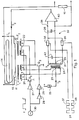
- Fig. 1 shows two identical toroidal transformers T, and T 2 respectively having cores 11 and 12, which are as identical as possible and made of a ferromagnetic material.
- the cores are wound in common with a primary winding 13 carrying the main current 1 1 to be measured, and a secondary winding 14 conducting a compensation current 1 2 ,
- a primary winding 13 carrying the main current 1 1 to be measured
- a secondary winding 14 conducting a compensation current 1 2
- the primary and secondary currents induces magnetic fields in the cores 11 and 12 in opposite directions. If the ampere-turns of the primary and secondary windings are equal, then the flux in the two cores will be zero and the ratio between the primary current and the secondary current is given by the ratio between the number of turns of the primary and the secondary windings. As this applies to d.c.
- the set-up works as a d.c.- transformer, in which the current on the primary side may be determined by measuring the current on the secondary side.
- This principle is inter alia used in measuring the heavy magnetizing currents, in the order of magnitude of kiloamperes, used for magnetic current supplies for particle accelerators.
- the secondary current 1 2 is conducted through a high precision measuring resistor 15, and the voltage drop across this resistor is used as an indication of the intensity of the secondary current 1 2 and thus indirectly the intensity of the primary current 1 1 .
- these are each wound with an individual sensing winding 21 and 22, respectively, through which is conducted a magnetizing current 1 3 supplied by a current limiting generator or current limited voltage source 23.
- a current limiting generator or current limited voltage source 23 In order to protect the following circuits, e.g., the synchronous rectifier, it is necessary to limit the current supplied to a certain maximum. This is conveniently indicated by the symbol for a constant current generator.
- the sensing windings 21 and 22 are wound so that the induced voltages are opposite in phase. This is indicated by the usual dot marking.
- each of the two sensing windings 21 and 22 are divided into two identical windings a and a' along with b and b', so that the ampere-turns thereof are substantially equal.
- Complete equality is impossible because the cores may not be manufactured identically.
- the cores will thus differ from one another e.g. on sintering and on sectional area. It would be necessary to include small adjusting means in each winding, in order to obtain the same ampere-turns in all four windings, but this is not shown on the drawing for reason of simplification, and because this is elementary for a skilled person.
- the current limited voltage source 23 supplies magnetizing current to the subwindings 21a, 21a', 22b and 22b' through the primary winding 24 of the auxiliary transformer T 3 , which primary winding at a center tap 25 thereof is connected to said source 23.
- the dot marked end of a winding will be named below as the plus-terminal and the opposite end thereof the minus-terminal.
- each of the sensing windings e.g., 21a' and 22b
- the opposite end of the said primary winding is connected to the two other subwindings. i.e., 21a and 22b', at their minus-terminal.
- the remaining four terminals are so connected, that the plus-terminal of subwinding a and the minus-terminal of subwinding b are connected to the source-drain junction of a first transistor Q l , while the minus-terminal of subwinding a' and the plus-terminal of subwinding b' are connected to the source-drain junction of a second transistor Q Z .
- the gate terminals of the two transistors Q 1 and Q 2 are via switch means 27, 28 and 29 respectively, connected to a signal generator 30 the output of which is a symmetrical square wave voltage at the frequency, f, the order of magnitude of which could be e.g. 1 MHz.
- a signal will be applied via the switch means 27 to the gating terminal of the first transistor Q 1 , so that magnetizing current is conducted through a subwinding of each sensing winding a and b, the induced fields of which counteract one another, whereas during the negative half periods, a signal will be applied via the switch means 28 and 29 to the gating terminal of the second transistor Q 2 , so that magnetizing current is conducted through the other subwindings a' and b' of each of the sensing windings, the fields of which also counteract one another.
- the flux induced in the first toroid T 1 by the magnetizing current through the primary coil or winding of the auxiliary transformer T 3 e.g. the flux provided by the subwinding a, or more correctly speaking, the electromotive forces induced by this flux will be neutralized completely by the corresponding flux induced in the second toroid T 2 by means of the subwinding b, as long as the system is in balance, i.e. as long as the main current 1 1 corresponds to the compensation current 1 2 as far as the ampere-turns is concerned.
- the secondary winding 31 is earthed or grounded via a centertap 33, while the outer terminals thereof via a pair of analog switch devices 34 and 35 are connected to an output terminal 36 of the rectifier.
- the analog switch devices 34 and 35 are controlled by a pair of square wave signals 37 and 38, which are in counterphase, and the frequency of which is twice the frequency of the control signal to the transistors Q 1 and Q 2 .
- This implies that the shown synchronous rectifier is embodied as a full wave rectifier and operates relative to the magnetizing currents in the sensing windings 21 and 22 according to the push-pull principle.
- the rectified signal is smoothed by a capacitor 39 so that the detector output on terminal 36 is a d.c.
- the detector signal at the output terminal 36 is applied to a compensation amplifier 40, which, according to the detector signal at the input terminal, in a known way adjusts the compensation current 1 2 to increase or decrease it in order to reestablish the balance, so that the mean flux of the cores is zeroed again.
- the magnetizing currents to the sensing windings not necessarily are to be supplied through a center tap on the primary winding of the auxiliary transformer T 3 but may just as well be supplied from a symmetrical voltage source of the same kind as described below and shown in Fig. 2.
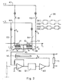
- FIG. 2 A second embodiment of the detector circuit is shown in Fig. 2.
- the toroidal cores 11 and 12 having the sensing windings 21 and 22 divided into subwindings a, a', b and b'.
- the dot markings are as above.
- the toroidal transformer having primary and secondary windings 13 and 14 along with the measuring resistor 15 positioned like in the first embodiment.
- each toroid is connected in series with a minus-terminal to a plus-terminal for the subwindings a and a', and with a plus-terminal to a minus-terminal for the subwindings b and b' which provide each sensing winding 21 and 22, respectively, with a center tap.
- These center taps are in turn connected to a common junction 45 which is connected to the synchronous rectifier 32 via a summing amplifier 46.
- the summing amplifier may of course be replaced by a summing resistor, which is indicated in dashed lines.
- the synchronous rectifier is in turn connected to the compensation amplifier 40.
- the four subwindings receive magnetizing currents from a dual voltage supply having a positive terminal 47 and a negative terminal 48 via four switch means 51, 52, 53 and 54, so that the plus-terminal of the first sensing winding 21 and minus-terminal of the second winding 22 are connected to the positive terminal 47 via the first and the third switch means 51 and 53 respectively, while the minus-terminal of the first sensing winding 21 and the plus-terminal of the second sensing winding 22 are connected to the negative terminal 48 via the second and fourth switch means 52 and 54, respectively.
- the signatures for constant current generators which here means that a sort of current limitation is provided.
- Such a current limiter may in its simpliest form consist of a resistor, but may just as well be a facility included in the shown switch device. Whether the current limiter is provided on the one or the other side of the switch is unimportant.
- the control signals for the opening and closing of the switches are generally indicated by reference numeral 55. It is shown, that the first and fourth switch means go together in counterphase with the second and third ones, so that odd-harmonic components here, as above, are outbalanced against each other, while the even-harmonic components are summed just as in the first described embodiment.
- This second embodiment distinguishes itself by not comprising any auxiliary transformer, which opens the possibility of designing a very compact and relatively inexpensive embodiment of the complete current detector employing integrated circuit technology, largely without giving away any of the advantages described above in connection with the first embodiment.
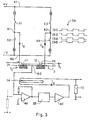
- FIG. 3 presents an alternative to the embodiment shown in Fig. 2.
- the reference numerals will consequently be the same, too.
- all four subwindings are connected in series, so that the sensing windings 21 and 22 are interconnected at their minus-terminal to form a common junction 60 which is connected to the input terminal of the summing amplifier 46.
- the summing amplifier be replaced by a summing resistor as indicated in dashed lines.
- the first and second switch means 51 and 52 are further connected in series between positive and negative terminals 47 and 48 of the voltage source, and with a common junction 61 thereof connected to the plus-terminal of the first sensing winding 21 while the third and fourth switch means 53 and 54 are connected in series between said voltage source terminals and with a common junction 62 thereof connected to the plus-terminal of the second sensing winding 22.
- the detector circuit is intended for d.c. measurements, but it should be added here, that it is suitable for a.c. current measurements as well. Neither are the application fields limited to magnetic current supplies for particle accelerators, but cover all areas, where there is a need for galvanic separation between the measuring circuit and the circuit to be measured on. Above a detector circuit for current measurements is disclosed. According to the invention for the measurement of large currents, d.c. as well as a.c., a so called zero-flux current transformer is used.
- It comprises two identically wound toroidal cores 11, 12, in which the magnetic flux induced by a main or primary current 1 1 is neutralized by a counter-flux induced by a compensation current 1 2 , which by means of an amplifier circuit 40 is passed through a compensation winding 14 common for both cores 11, 12 and having many turns.
- the compensation current 1 2 is adjusted by means of the amplifier 40 to such a value, that the mean flux in the cores 11, 12 is zero.
- the intensity of the compensation current 1 2 is measured by the voltage drop across a measuring resistor 15.
- any unbalances between the primary and secondary ampere-turns are sensed by a detecting circuit comprising a sensing winding 21, 22 wound on each core 11, 12 and divided into two subwindings which carries a magnetizing current 1 3 from a current limited voltage source 23 in such a way, that the odd-harmonic components contained in the magnetizing current are outbalanced, whilst the even-harmonic components contained therein are added and conducted to a synchronous rectifier 32 to provide a control signal to the amplifier 40 for the adjusting of the compensation current I 2 .
Landscapes
- Engineering & Computer Science (AREA)
- Power Engineering (AREA)
- Physics & Mathematics (AREA)
- General Physics & Mathematics (AREA)
- Measurement Of Current Or Voltage (AREA)
- Measuring Instrument Details And Bridges, And Automatic Balancing Devices (AREA)
- Investigating Or Analyzing Materials By The Use Of Electric Means (AREA)
- Investigating Or Analysing Materials By Optical Means (AREA)
- Transmission And Conversion Of Sensor Element Output (AREA)
- Measuring Volume Flow (AREA)
- Arrangements For Transmission Of Measured Signals (AREA)
Claims (4)
Priority Applications (1)
| Application Number | Priority Date | Filing Date | Title |
|---|---|---|---|
| AT84110994T ATE40604T1 (de) | 1983-09-15 | 1984-09-14 | Strommessdetektorschaltung. |
Applications Claiming Priority (2)
| Application Number | Priority Date | Filing Date | Title |
|---|---|---|---|
| DK421683A DK149238C (da) | 1983-09-15 | 1983-09-15 | Detektorkredslaeb til brug ved straemmaaling |
| DK4216/83 | 1983-09-15 |
Publications (2)
| Publication Number | Publication Date |
|---|---|
| EP0137347A1 EP0137347A1 (fr) | 1985-04-17 |
| EP0137347B1 true EP0137347B1 (fr) | 1989-02-01 |
Family
ID=8131391
Family Applications (1)
| Application Number | Title | Priority Date | Filing Date |
|---|---|---|---|
| EP84110994A Expired EP0137347B1 (fr) | 1983-09-15 | 1984-09-14 | Dispositif de détection pour la mesure du courant élastique |
Country Status (6)
| Country | Link |
|---|---|
| US (1) | US4616174A (fr) |
| EP (1) | EP0137347B1 (fr) |
| JP (1) | JPS60173477A (fr) |
| AT (1) | ATE40604T1 (fr) |
| DE (1) | DE3476586D1 (fr) |
| DK (1) | DK149238C (fr) |
Cited By (1)
| Publication number | Priority date | Publication date | Assignee | Title |
|---|---|---|---|---|
| DE3940932A1 (de) * | 1989-12-12 | 1991-06-13 | Ulrich Doerr | Messwandler |
Families Citing this family (49)
| Publication number | Priority date | Publication date | Assignee | Title |
|---|---|---|---|---|
| DE3521546A1 (de) * | 1985-06-15 | 1986-12-18 | LGZ Landis & Gyr Zug AG, Zug | Elektrischer ueberlastanzeiger |
| US4761605A (en) * | 1986-12-22 | 1988-08-02 | General Electric Company | Input switching in electronic watthour meter |
| US4749940A (en) * | 1986-12-22 | 1988-06-07 | General Electric Company | Folded bar current sensor |
| US4899103A (en) * | 1987-07-16 | 1990-02-06 | Brooktree Corporation | Current meter |
| US4841236A (en) * | 1988-03-22 | 1989-06-20 | Canadian Patents And Development Limited-Societe Canadienne Des Brevets Et D'exploitation Limitee | Current ratio device |
| US5008612A (en) * | 1988-08-24 | 1991-04-16 | Unisearch Systems Limited | Current sensor |
| US5041780A (en) * | 1988-09-13 | 1991-08-20 | California Institute Of Technology | Integrable current sensors |
| US5066904A (en) * | 1988-10-18 | 1991-11-19 | General Electric Company | Coaxial current sensors |
| US4970459A (en) * | 1988-12-02 | 1990-11-13 | General Electric Company | Electronic meter chopper stabilization |
| GB2244142A (en) * | 1990-05-16 | 1991-11-20 | Westinghouse Brake & Signal | Current transformer measuring circuits |
| CH684216A5 (fr) * | 1991-02-15 | 1994-07-29 | Lem Liaisons Electron Mec | Dispositif de mesure de courants. |
| FI90142C (fi) * | 1992-04-02 | 1993-12-27 | Abb Stroemberg Drives Oy | Enligt kompensationsprincip fungerande maetomvandlare foer stroem |
| FI98411C (fi) * | 1993-08-20 | 1997-06-10 | Picker Nordstar Oy | Parannettu virtalähde |
| EP0686850A1 (fr) * | 1994-06-09 | 1995-12-13 | Lem S.A. | Circuit de mesure de courants continus avec isolation de tension entre le circuit de courant et le circuit de mesure |
| US5568047A (en) * | 1994-08-10 | 1996-10-22 | General Electric Company | Current sensor and method using differentially generated feedback |
| FR2753594B1 (fr) * | 1996-09-17 | 1998-12-11 | Sagem | Telecopieur a interface de ligne a detecteur unique et detecteur de courant a circuits magnetiques de detection et de compensation |
| JP3583586B2 (ja) * | 1997-07-22 | 2004-11-04 | 株式会社東芝 | 電力変換装置の制御装置 |
| US6175255B1 (en) * | 1998-11-23 | 2001-01-16 | National Seniconductor Corporation | Line driver circuit for low voltage and low power applications |
| FR2788344B1 (fr) * | 1999-01-12 | 2001-03-30 | Peugeot Citroen Automobiles Sa | Dispositif de mesure d'un courant circulant dans un conducteur |
| US6522517B1 (en) | 1999-02-25 | 2003-02-18 | Thomas G. Edel | Method and apparatus for controlling the magnetization of current transformers and other magnetic bodies |
| US6246593B1 (en) * | 1999-05-06 | 2001-06-12 | Astec International Limited | Topology-independent synchronous rectifier commutation circuit |
| US6356421B1 (en) * | 1999-11-29 | 2002-03-12 | Schweitzer Engineering Labs., Inc. | System for power transformer differential protection |
| JP2001201521A (ja) * | 2000-01-18 | 2001-07-27 | Agilent Technologies Japan Ltd | 電流検出装置及びインピーダンス測定器及び電力測定装置 |
| DE60222594T2 (de) * | 2002-06-25 | 2008-06-19 | Grno, Ladislav, Dr. | Schaltung zum gleichzeitigen testen von elektrizitätszählern mit verbundenen strom- und spannungseingängen |
| AU2003265365A1 (en) * | 2002-08-05 | 2004-02-23 | Engineering Matters, Inc. | Self-powered direct current mitigation circuit for transformers |
| US6954060B1 (en) | 2003-03-28 | 2005-10-11 | Edel Thomas G | a-c current transformer functional with a d-c current component present |
| JP4842275B2 (ja) * | 2004-11-05 | 2011-12-21 | リエゾン エレクトロニク・メカニク レム ソシエテ アノニム | 電流測定のための検出回路 |
| DK200500029A (da) | 2005-01-07 | 2006-07-08 | Danfysik As | Detektorkredslöb til brug ved strömmåling |
| CN100432680C (zh) * | 2005-08-24 | 2008-11-12 | 珠海市科荟电器有限公司 | 钳形互感器、钳形电流表和钳形电流表自校正方法 |
| US8619443B2 (en) | 2010-09-29 | 2013-12-31 | The Powerwise Group, Inc. | System and method to boost voltage |
| US8085009B2 (en) | 2007-08-13 | 2011-12-27 | The Powerwise Group, Inc. | IGBT/FET-based energy savings device for reducing a predetermined amount of voltage using pulse width modulation |
| US8085010B2 (en) | 2007-08-24 | 2011-12-27 | The Powerwise Group, Inc. | TRIAC/SCR-based energy savings device for reducing a predetermined amount of voltage using pulse width modulation |
| US8120307B2 (en) | 2007-08-24 | 2012-02-21 | The Powerwise Group, Inc. | System and method for providing constant loading in AC power applications |
| US8698447B2 (en) | 2007-09-14 | 2014-04-15 | The Powerwise Group, Inc. | Energy saving system and method for devices with rotating or reciprocating masses |
| US8810190B2 (en) | 2007-09-14 | 2014-08-19 | The Powerwise Group, Inc. | Motor controller system and method for maximizing energy savings |
| US8823314B2 (en) | 2007-09-14 | 2014-09-02 | The Powerwise Group, Inc. | Energy saving system and method for devices with rotating or reciprocating masses |
| JP5340639B2 (ja) * | 2008-05-22 | 2013-11-13 | ローム株式会社 | キャパシタ充電装置およびその制御回路、制御方法、ならびにそれらを用いた発光装置および電子機器 |
| US8004255B2 (en) | 2008-08-07 | 2011-08-23 | The Powerwise Group, Inc. | Power supply for IGBT/FET drivers |
| US8159240B2 (en) * | 2009-01-09 | 2012-04-17 | Tdk Corporation | Bulk current injection (BCI) probe with multiple, symmetrically spaced feeds |
| US8698446B2 (en) | 2009-09-08 | 2014-04-15 | The Powerwise Group, Inc. | Method to save energy for devices with rotating or reciprocating masses |
| US9155585B2 (en) * | 2010-01-12 | 2015-10-13 | Syntheon, Llc | Battery-powered electrosurgical forceps with multi-turn selectable-ratio transformer |
| CN103901252B (zh) * | 2014-04-08 | 2018-11-02 | 烟台市华能电器有限公司 | 10kv输电线路零序电流检测系统 |
| JP6625395B2 (ja) * | 2015-10-26 | 2019-12-25 | 日置電機株式会社 | 電流センサおよび測定装置 |
| CN105510679A (zh) * | 2016-01-21 | 2016-04-20 | 江苏省电力公司电力科学研究院 | 高可靠性高精度电流测量方法及装置 |
| US9618541B1 (en) * | 2016-04-20 | 2017-04-11 | Neilsen-Kuljian, Inc. | Apparatus, method and device for sensing DC currents |
| WO2017214035A1 (fr) | 2016-06-06 | 2017-12-14 | Aerovironment, Inc. | Transformateur de détection de courant résiduel (rcd) et de surveillance d'impédance de masse et procédés de commande |
| FR3060757B1 (fr) * | 2016-12-19 | 2020-11-06 | Safran Electronics & Defense | Capteur de courant a vanne de flux |
| JP6829139B2 (ja) * | 2017-04-11 | 2021-02-10 | 日置電機株式会社 | 電流センサおよび測定装置 |
| FR3083321B1 (fr) * | 2018-06-27 | 2021-03-05 | Safran Electronics & Defense | Capteur de courant a vanne de flux |
Family Cites Families (4)
| Publication number | Priority date | Publication date | Assignee | Title |
|---|---|---|---|---|
| GB1345869A (en) * | 1971-11-30 | 1974-02-06 | Secr Defence | Electrical current measuring instruments |
| US3801907A (en) * | 1972-10-12 | 1974-04-02 | M Lilienstein | Direct current measurement |
| US4278939A (en) * | 1979-07-27 | 1981-07-14 | Bell Telephone Laboratories, Incorporated | Electromagnetic arrangement for measuring electrical current |
| US4274051A (en) * | 1979-07-27 | 1981-06-16 | Bell Telephone Laboratories, Incorporated | Electromagnetic arrangement for measuring electrical current |
-
1983
- 1983-09-15 DK DK421683A patent/DK149238C/da not_active IP Right Cessation
-
1984
- 1984-09-14 US US06/650,718 patent/US4616174A/en not_active Expired - Fee Related
- 1984-09-14 EP EP84110994A patent/EP0137347B1/fr not_active Expired
- 1984-09-14 AT AT84110994T patent/ATE40604T1/de not_active IP Right Cessation
- 1984-09-14 DE DE8484110994T patent/DE3476586D1/de not_active Expired
- 1984-09-17 JP JP59195624A patent/JPS60173477A/ja active Pending
Cited By (1)
| Publication number | Priority date | Publication date | Assignee | Title |
|---|---|---|---|---|
| DE3940932A1 (de) * | 1989-12-12 | 1991-06-13 | Ulrich Doerr | Messwandler |
Also Published As
| Publication number | Publication date |
|---|---|
| DK421683A (da) | 1985-03-16 |
| DK149238C (da) | 1987-01-19 |
| JPS60173477A (ja) | 1985-09-06 |
| ATE40604T1 (de) | 1989-02-15 |
| DE3476586D1 (en) | 1989-03-09 |
| DK149238B (da) | 1986-04-01 |
| DK421683D0 (da) | 1983-09-15 |
| EP0137347A1 (fr) | 1985-04-17 |
| US4616174A (en) | 1986-10-07 |
Similar Documents
| Publication | Publication Date | Title |
|---|---|---|
| EP0137347B1 (fr) | Dispositif de détection pour la mesure du courant élastique | |
| US5223789A (en) | AC/DC current detecting method | |
| US4596950A (en) | Compensated transducer | |
| US2338423A (en) | Apparatus for measuring direct currents or voltages | |
| RU2114439C1 (ru) | Устройство для измерения тока | |
| GB1032867A (en) | Improvements in or relating to magnetometers | |
| DK577588D0 (da) | Kredsloeb til detektering af asymmetri i magnetiseringsstroemmen i en magnetisk modulator | |
| GB2265722A (en) | Current measuring transducer operating on the compensation principle | |
| US3007106A (en) | Current meter and probe therefor | |
| US2760158A (en) | Method and apparatus for measuring electrical current | |
| US3818337A (en) | METHOD OF AND APPARATUS FOR IMPROVING THE LINEARITY OF THE CURREnT TRANSFORMATION OF A DC MEASURING TRANSDUCTOR | |
| US4163189A (en) | Transformer with a ferromagnetic core for d-c and a-c signals | |
| US6078172A (en) | Current-compensated current sensor for hysteresis-independent and temperature-independent current measurement | |
| JPS6395363A (ja) | 電流センサおよび被評価導体中の電流検出方法 | |
| US4461987A (en) | Current sensing circuit for motor controls | |
| US2996682A (en) | Variable inductance device | |
| EP0278635B1 (fr) | Appareil d'alimentation de puissance à contre-réaction | |
| US4467662A (en) | Signal rectifier, especially for magnetoelastic transducers | |
| US2917238A (en) | Saturable reactor computer | |
| US3333192A (en) | Second harmonic magnetic modulator measuring system | |
| EP0067153B1 (fr) | Detecteur a amplificateur magnetique a noyau double | |
| SU1620844A1 (ru) | Устройство дл измерени расхода жидких и газообразных сред | |
| FI67963B (fi) | Kopplingsarrangemang foer att reglera magnetiseringsstroem | |
| Leehey et al. | DC current transformer | |
| JPS631253Y2 (fr) |
Legal Events
| Date | Code | Title | Description |
|---|---|---|---|
| PUAI | Public reference made under article 153(3) epc to a published international application that has entered the european phase |
Free format text: ORIGINAL CODE: 0009012 |
|
| AK | Designated contracting states |
Designated state(s): AT BE CH DE FR GB IT LI LU NL SE |
|
| 17P | Request for examination filed |
Effective date: 19850920 |
|
| 17Q | First examination report despatched |
Effective date: 19861209 |
|
| GRAA | (expected) grant |
Free format text: ORIGINAL CODE: 0009210 |
|
| AK | Designated contracting states |
Kind code of ref document: B1 Designated state(s): AT BE CH DE FR GB IT LI LU NL SE |
|
| PG25 | Lapsed in a contracting state [announced via postgrant information from national office to epo] |
Ref country code: SE Effective date: 19890201 Ref country code: NL Effective date: 19890201 Ref country code: BE Effective date: 19890201 Ref country code: AT Effective date: 19890201 |
|
| REF | Corresponds to: |
Ref document number: 40604 Country of ref document: AT Date of ref document: 19890215 Kind code of ref document: T |
|
| ITF | It: translation for a ep patent filed |
Owner name: STUDIO CONS. BREVETTUALE S.R.L. |
|
| REF | Corresponds to: |
Ref document number: 3476586 Country of ref document: DE Date of ref document: 19890309 |
|
| ET | Fr: translation filed | ||
| NLV1 | Nl: lapsed or annulled due to failure to fulfill the requirements of art. 29p and 29m of the patents act | ||
| PG25 | Lapsed in a contracting state [announced via postgrant information from national office to epo] |
Ref country code: LU Free format text: LAPSE BECAUSE OF NON-PAYMENT OF DUE FEES Effective date: 19890930 |
|
| PLBE | No opposition filed within time limit |
Free format text: ORIGINAL CODE: 0009261 |
|
| STAA | Information on the status of an ep patent application or granted ep patent |
Free format text: STATUS: NO OPPOSITION FILED WITHIN TIME LIMIT |
|
| 26N | No opposition filed | ||
| ITTA | It: last paid annual fee | ||
| PGFP | Annual fee paid to national office [announced via postgrant information from national office to epo] |
Ref country code: GB Payment date: 19920911 Year of fee payment: 9 |
|
| PGFP | Annual fee paid to national office [announced via postgrant information from national office to epo] |
Ref country code: FR Payment date: 19920917 Year of fee payment: 9 |
|
| PGFP | Annual fee paid to national office [announced via postgrant information from national office to epo] |
Ref country code: CH Payment date: 19920928 Year of fee payment: 9 |
|
| PGFP | Annual fee paid to national office [announced via postgrant information from national office to epo] |
Ref country code: DE Payment date: 19921127 Year of fee payment: 9 |
|
| PG25 | Lapsed in a contracting state [announced via postgrant information from national office to epo] |
Ref country code: GB Effective date: 19930914 |
|
| PG25 | Lapsed in a contracting state [announced via postgrant information from national office to epo] |
Ref country code: LI Effective date: 19930930 Ref country code: CH Effective date: 19930930 |
|
| GBPC | Gb: european patent ceased through non-payment of renewal fee |
Effective date: 19930914 |
|
| PG25 | Lapsed in a contracting state [announced via postgrant information from national office to epo] |
Ref country code: FR Free format text: LAPSE BECAUSE OF NON-PAYMENT OF DUE FEES Effective date: 19940531 |
|
| REG | Reference to a national code |
Ref country code: CH Ref legal event code: PL |
|
| PG25 | Lapsed in a contracting state [announced via postgrant information from national office to epo] |
Ref country code: DE Effective date: 19940601 |
|
| REG | Reference to a national code |
Ref country code: FR Ref legal event code: ST |