EP0136390A1 - Apparatus for presenting the gore opening of panty hose without wrinkles to a gores sewing machine - Google Patents
Apparatus for presenting the gore opening of panty hose without wrinkles to a gores sewing machine Download PDFInfo
- Publication number
- EP0136390A1 EP0136390A1 EP83830181A EP83830181A EP0136390A1 EP 0136390 A1 EP0136390 A1 EP 0136390A1 EP 83830181 A EP83830181 A EP 83830181A EP 83830181 A EP83830181 A EP 83830181A EP 0136390 A1 EP0136390 A1 EP 0136390A1
- Authority
- EP
- European Patent Office
- Prior art keywords
- support
- machine according
- rods
- horizontal
- groove
- Prior art date
- Legal status (The legal status is an assumption and is not a legal conclusion. Google has not performed a legal analysis and makes no representation as to the accuracy of the status listed.)
- Granted
Links
Images


Classifications
-
- D—TEXTILES; PAPER
- D05—SEWING; EMBROIDERING; TUFTING
- D05B—SEWING
- D05B23/00—Sewing apparatus or machines not otherwise provided for
- D05B23/007—Sewing units for assembling parts of knitted panties or closing the stocking toe part
- D05B23/008—Line closers, i.e. sewing units for forming the body portion of the panty hose
-
- D—TEXTILES; PAPER
- D05—SEWING; EMBROIDERING; TUFTING
- D05D—INDEXING SCHEME ASSOCIATED WITH SUBCLASSES D05B AND D05C, RELATING TO SEWING, EMBROIDERING AND TUFTING
- D05D2207/00—Use of special elements
- D05D2207/02—Pneumatic or hydraulic devices
- D05D2207/04—Suction or blowing devices
-
- D—TEXTILES; PAPER
- D05—SEWING; EMBROIDERING; TUFTING
- D05D—INDEXING SCHEME ASSOCIATED WITH SUBCLASSES D05B AND D05C, RELATING TO SEWING, EMBROIDERING AND TUFTING
- D05D2303/00—Applied objects or articles
- D05D2303/20—Small textile objects e.g., labels, beltloops
Definitions
- the invention relates to a machine for sewing bellows on knitted garments of the sticky type with automated feeding.
- n ° 504.417 we know an automatic machine with which a knitted garment like the knitted tights or jerseys so-called is taken from a machine which performs the seams of two stockings to form the body of the garment, for the stiffened edge in the round of the zone left without seams and intended for a bellows by means of an annular clamp with radially separable elements and successively the garment is positioned, with the said stiffened edge, concentrically outside of the horizontal circular entry of the support of a machine which applies and sews the bellows fluff and consequently the said garment is transferred to the said support after which all the garment is sucked up inside the support leaving externally, on the lower area of the support, a sufficient amount of fabric for sewing the sufflet.
- the present invention proposes to eliminate this drawback. This result was achieved in accordance with the invention by adopting the idea of stretching the body and legs of the garment lengthwise, before and during the aspiration of the body inside the support, retaining stiffened in round the edge of the sewing fabrics with the bellows.
- the machine which is the subject of the invention essentially provides means for retaining and stiffening in a circle the edge of the fabric to be sewn with the bellows and means for stretching the body and the legs of the garment in length and for approaching said body, by keeping taut, at the entrance of the support during its aspiration inside the support itself, and possibly means for operating successively, from inside the support, a further stiffening of the edge of the tissue adhering to the support.
- the advantages obtained with the present invention consist essentially in the fact that the garment is moved on the gusset sewing machine without the formation of grimaces in the edge of the fabric to be gusseted with any type of fabric and thus m 'eme si very elastic; that said movement is automated and therefore very rapid.
- the operation is as follows.
- the cylinder 80 is activated so that the fork 90 by lifting the collar 50 causes the hooks 63 to spread apart with the effect, in combination with the lifting of the clamp 9, of taking and retaining on the rods 60 the garment by the stiffened edge round the fabric to be sewn on the gusset; successively, the legs 36 are sucked into the pipes 20, the buffer clamp 10-10 is closed, thereby obtaining hold of the body 35 of the garment and afterwards the said clamp 10-10 is lowered, thereby obtaining the lengthening of the body (as illustrated in FIG.2) after which the pneumatic suction is activated inside the support 40 and at the same time the clamp 10-10 is approached near the mouth 42 of the support 40 (as illustrated in FIG.
- the pad 12 is activated which, being introduced with a slight elastic forcing in the mouth 42 of the support 40, operates a complete and final flattening of the tissue which is located near said mouth 42 (as illustrated in FIG. 5) by putting its edge in order for a correct sewing of the bellows.
Abstract
Description
L'invention concerne une machine à coudre les soufflets sur vêtements en tricot du type collant avec alimentation automatisée.The invention relates to a machine for sewing bellows on knitted garments of the sticky type with automated feeding.
D'après le brevet espagnol n° 504.417 on connait une machine automatique avec lequel un vêtement en tricot comme les collants ou maillots en tricot ainsi-nommés est prélevé d'une machine qui effectue les coutures d'union de deux bas pour former le corps du vêtement, pour le bord raidi en rond de la zone laissée sans coutures et destinée à un sufflet au moyen d'une pince annulaire à éléments radialement écartables et successivement le vêtement est positionné, avec le dit bord raidi,concentriquement à l'extérieur de l'entrée circulaire horizontale du support d'une machine qui applique et coud les souf flets et en conséquence le dit vêtement est transféré sur le dit support après quoi tout le vêtement est aspiré vers le haut à l'intérieur du support en laissant extérieurement, sur la zone inférieure du support, une quantité de tissu suffisante pour la couture du sufflet.According to the Spanish patent n ° 504.417 we know an automatic machine with which a knitted garment like the knitted tights or jerseys so-called is taken from a machine which performs the seams of two stockings to form the body of the garment, for the stiffened edge in the round of the zone left without seams and intended for a bellows by means of an annular clamp with radially separable elements and successively the garment is positioned, with the said stiffened edge, concentrically outside of the horizontal circular entry of the support of a machine which applies and sews the bellows fluff and consequently the said garment is transferred to the said support after which all the garment is sucked up inside the support leaving externally, on the lower area of the support, a sufficient amount of fabric for sewing the sufflet.
On sait aussi que pendant cette dernière opération spécialement avec quelques types de tissu très élas tique, dans le bord à coudre se forment beaucoup de grimaces ou plis qui, avec la couture successive du sufflet, restent en permanence dans le vêtement fini, de sorte que sa qualité en resulte fortement préjudiciée.We also know that during this last operation especially with some very elastic types of fabric, in the sewing edge many grimaces or folds form which, with the successive sewing of the sufflet, remain permanently in the finished garment, so that its quality results strongly prejudiced.
La présente invention se propose d'éliminer cet inconvénient.
A ce résultat on est parvenu en conformité de l'invention en adoptant l'idée de tendre en longueur le corps et les jambes du v"etement, avant et pendant l'aspiration du corps à l'intérieur du support, en retenant raidi en rond le bord di tissus à coudre au soufflet.The present invention proposes to eliminate this drawback.
This result was achieved in accordance with the invention by adopting the idea of stretching the body and legs of the garment lengthwise, before and during the aspiration of the body inside the support, retaining stiffened in round the edge of the sewing fabrics with the bellows.
Dans ce but la machine objet de l'invention prévoit essentiellement des moyens pour retenir et raidir en rond le bord du tissu à coudre au soufflet et moyens pour tendre en longueur le corps et les iambes du vêtement et pour approcher le dit corps, en le gardant tendu, à l'entrée du support pendant son aspiration à l'intérieur du support lui-même, et éventuellement moyens pour opérer successivement, de l'intérieur du support, un ultérieur raidissage du bord du tissu adhérent au support.To this end, the machine which is the subject of the invention essentially provides means for retaining and stiffening in a circle the edge of the fabric to be sewn with the bellows and means for stretching the body and the legs of the garment in length and for approaching said body, by keeping taut, at the entrance of the support during its aspiration inside the support itself, and possibly means for operating successively, from inside the support, a further stiffening of the edge of the tissue adhering to the support.
Les avantages obtenus avec la présente invention consistent essentiellement en ce qu' on réalise le déplacement du vêtement sur la machine à coudre les soufflets sans formation de grimaces dans le bord du tissu à coudre au soufflet avec n'importe quel type de tissu et ainsi m'eme si très élastique; que le dit déplacement est automatisé et partant très rapide.The advantages obtained with the present invention consist essentially in the fact that the garment is moved on the gusset sewing machine without the formation of grimaces in the edge of the fabric to be gusseted with any type of fabric and thus m 'eme si very elastic; that said movement is automated and therefore very rapid.
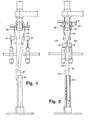
Ceux-ci et ultérieurs avantages et caractéristiques de l'invention serontcompris davantage et mieux par tout technicien de cette branche grâce à la descrip tion qui suit et à l'aide des dessins joints donnés comme explication au moyens d'exemples pratiques;où dans le TAB.1 la FIG.1 représente la vue schématique d'ensemble des moyens inactifs pour retenir le vêtement et pour tendre en longueur le corps et les jambes pour une machine suivant l'invention et pendant que le vêtement est encore retenu par le dispo sitif d'alimentation; la FIG.2 représente les dits moyens de la FIG.1 en phase active, immédiatement après la prise du vêtement;
- dans le TAB 2 la FIG.3 représente les dits moyens de FIG.1 en phase active pendant l'aspiration du corps à l'intérieur du support; la FIG.4 représente les dits moyens de FIG.1 après la complète aspiration du corps dans le support et pendant l'aspiration dans le dit support d'une des jambes;
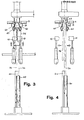
- dans le TAB.3 la FIG.5 représente inactifs les moyens supplémentaires de raidissage du bord du tissu adhérent au support après la complète aspiration du vêtement à l'intérieur du support; la FIG.6 représente les moyens alternatifs pour tendre le corps du vêtement avant son aspiration à 1' intérieur du support;
- dans le TAB.4 la FIG.7 représente en section verticale le détail de la tAete de la machine suivant l' invention et dans lequel la moitié de gauche montre le
collier 50 en position soulevée et la moitié de droite montre le mAeme collier 50 en position abaissée.
- in TAB 2 FIG.3 represents the said means of FIG.1 in active phase during the aspiration of the body inside the support; FIG.4 shows the said means of FIG.1 after the complete aspiration of the body in the support and during the aspiration in the said support of one of the legs;
- in TAB.3 FIG.5 shows inactive the additional means of stiffening the edge of the fabric adhering to the support after the complete suction of the garment inside the support; FIG. 6 represents the alternative means for stretching the body of the garment before it is drawn inside the support;
- in TAB.4 FIG.7 shows in vertical section the detail of the t A summer of the machine according to the invention and in which the left half shows the
collar 50 in the raised position and the right half shows the m A th collar 50 in the lowered position.
Réduite à l'essentiel, une machine suivant l'inven- vention comprend:
- (a) une tête composée
- - d'un support tubulaire 40 avec embouchure 42 horizontale et muni, extérieurement, d'une
première gorge 43 hémicirculaire continue et supérieurement à la dite gorge, d'unedeuxième gorge 44 continue à séction triangulaire; - - d'un
collier 50 avecgorge 53, placé fou sur ledit support 40, muni de plusieursfentés 51 longitu dinales, équidistantes, pour installer autant detiges 60 disposées en rond, rectilignes, approchables verticalement à la surface extérieure dusupport 40, angulairement équidistantes et oscillantes verticalement àcharnière 61 dans lagorge 43 préci tée et avec l'extrémité supérieure 62 pénétrant dans lagorge 44 susdite et en mAeme temps écartant radialement l'extrémité inférieure 63 crochue; les ditestiges 60 sont en outre mounies d'unecheville 64 saillante transversalement vers l'extérieur, des tinée à `etre interceptée par unebride 52 ducollier 50 lorsque celui-ci baisse, avec l'effet d'approcher lestiges 60 au support 40: et chaque tige étant pourvue, en face ducrochet 63, d'unesaillie 65 qui coopère au désenfilement duvêtement 37 de lapince 9 et à son transfert sur lestiges 60 lors que lapince 9 du dispositif d'alimentation est sou levée; - - d'un anneau élastique 70 fermé autour de l'extré mité supérieure 62 des dites
tiges 60 avec l'effet de soulever, c'est à dire écarter, l'extrémité crochue 63 destiges 60 dusupport 40 lorsque les diteschevilles 64 ne sont pas interceptées par labride 51 précitée; - - d'un cylindre pneumatique 80 supporté dans la partie fixe de la machine dont la tige verticale commande une
fourche 90 horizontale, dont le point d'appui est en 91 et avec l'extrémité libre engagée dans lagorge 53 précitée ducollier 50 avec l'effet de soulever et abaisser le collier et causer ainsi l'érection et l'baissement respectivement, de l'extrémité crochue 63 destiges 60.
- - d'un support tubulaire 40 avec embouchure 42 horizontale et muni, extérieurement, d'une
- (b) Une pince à tampons 10-10 au-dessous de la tête précitée, en deux éléments 10-10 en gomme, compénétrants, mobiles horizontalement en sens discordant avec l'effet, respectivement,de serrer ou libérer le
corps 35 du vêtement et en outre mobiles verticalement, en sens concordant, avec l'effet de s'approcher ou s'éloigner, respectivement, du support précité. En alternative à la dite pince est prévu un aspirateur pneumatique 11 vertical, positionné coaxialement sous lesupport 40 précité et mobile verticalement. - (c) Deux aspirateurs pneumatiques 20 verticaux pour aspirer et tendre en longueur les
jambes 36 du vête ment. - (d) Un
tampon 12 en gomme, en forme de tasse avec plusieurstrous 13, positionnable coaxialement sous lesupport 40 et qu'on peut introduire verticalement dans l'embouchure 42 avec un léger forcement élastique.
- (a) a compound head
- - A
tubular support 40 with horizontal mouth 42 and provided, externally, with a first continuoussemicircular groove 43 and above said groove, with a secondcontinuous groove 44 with triangular section; - a
collar 50 withgroove 53, placed idly on saidsupport 40, provided withseveral slits 51 longitu dinales, equidistant, to install asmany rods 60 arranged in a circle, rectilinear, vertically approachable on the external surface ofsupport 40, angularly equidistant and vertically oscillatinghinge 61 in thegroove 43 Préci tee and with thetop 62 extending into theaforesaid groove 44 and m th time radially deviating the lower end hookedend 63; saidrods 60 are further provided with adowel 64 projecting transversely outward, to be intercepted by aflange 52 of thecollar 50 when the latter drops, with the effect of approaching therods 60 to the support 40: and each rod being provided, opposite thehook 63, with aprojection 65 which cooperates in unthreading thegarment 37 of theclamp 9 and in its transfer to therods 60 when theclamp 9 of the supply device is penny raised; - - An
elastic ring 70 closed around theupper end 62 of saidrods 60 with the effect of lifting, that is to say spreading, thehooked end 63 of therods 60 of thesupport 40 when the saidpins 64 are not intercepted by theflange 51 above; - - a pneumatic cylinder 80 supported in the fixed part of the machine, the vertical rod of which controls a
horizontal fork 90, the fulcrum of which is at 91 and with the free end engaged in theaforementioned groove 53 of thecollar 50 with the effect of raising and lowering the collar and thus causing the erection and the lowering respectively, of thehooked end 63 of therods 60.
- - A
- (b) 10-10 buffer pliers below the above-mentioned head, in two 10-10 rubber elements, penetrating, movable horizontally in discordant direction with the effect, respectively, of tightening or releasing the
body 35 of the garment and also movable vertically, in a concordant direction, with the effect of approaching or moving away, respectively, from the aforementioned support. As an alternative to said clamp, a verticalpneumatic vacuum cleaner 11 is provided, positioned coaxially under theaforementioned support 40 and movable vertically. - (c) Two vertical
pneumatic vacuum cleaners 20 for sucking and stretching thelegs 36 of the garment lengthwise. - (d) A
rubber pad 12, cup-shaped withseveral holes 13, positioned coaxially under thesupport 40 and which can be introduced vertically into the mouth 42 with a slight elastic forcing.
Le fonctionnement est le suivant.The operation is as follows.
Après que la pince 9 du dispositif d'alimentation automatique s'est disposée concentriquement au support 40 avec le vêtement 37 retenu au moyen des petites barres 19 et pendant que la pince à tampons 10-10 est ouverte et le tiges crochues 60 sont retirées (comme illustré dans la FIG.1) le cylindre 80 est activé de sorte que la fourche 90 en soulevant le collier 50 cause l'écartement des crochets 63 avec l'effet, en combinaison avec le soulèvement de la pince 9, de prélever et retenir sur les tiges 60 le vêtement par le bord raidi en rond du tissu à coudre au soufflet; successivement on aspire les jambes 36 dans les tuyaux 20, on ferme la pince à tampons 10-10 en obtenant avec cela de saisir le corps 35 du vêtement et après on abaisse la dite pince 10-10 en obtenant avec cela de tendre en longueur le corps (comme illustré dans la FIG.2) après quoi on active l'aspiration pneumatique à l'intérieur du support 40 et en même temps on approche la pince 10-10 à proximité de l'embouchure 42 du support 40 (comme illustré dans la FIG.3) en obtenant avec cela d'aspirer progressivement le corps 35 à l'intérieur du support 40 avec le tissu tendu et en conséquence sans que dans la zone qui couvre l'embouchure 42 du support 40 il y ait la formation de grimaces; lorsque la pince 10-10 est à proximité de l'embouchure 42 du support 40 elle s'ouvre et lorsque tout le corps 35 a été aspiré dans le support 40 on rend inactifs les aspirateurs 20 l'un après l'autre, afin que les jambes 36 soient aspirées séparément dans le même support 40 (comme illustré dans la FIG.4). Lorsque pour tendre le corps 35 on utilize l'aspirateur pneumatique 11 au lieu de la pince 10-10, alors on approche le tuyau 11 vers le support 40 et après que le corps 35 a été aspiré dans celui-ci, on procède à l'aspiration des jambes 36 dans le même support 40.After the
Après que tout le vêtement a été aspiré dans le support 40 et seulement dans le cas où il y a encore la présence de quelque grimace sur le bord du tissu à coudre au soufflet, on active le tampon 12 qui, on s'introduisant avec un léger forcement élas tique dans l'embouchure 42 du support 40, opère un aplatissement complet et définitif du tissus qui se trouve près de la dite embouchure 42 (comme illustré dans la FIG.5)en mettant son bord en ordre pour une couture correcte du soufflet.After all the clothing has been sucked into the
Claims (8)
Priority Applications (2)
| Application Number | Priority Date | Filing Date | Title |
|---|---|---|---|
| EP19830830181 EP0136390B1 (en) | 1983-09-22 | 1983-09-22 | Apparatus for presenting the gore opening of panty hose without wrinkles to a gores sewing machine |
| DE8383830181T DE3369862D1 (en) | 1983-09-22 | 1983-09-22 | Apparatus for presenting the gore opening of panty hose without wrinkles to a gores sewing machine |
Applications Claiming Priority (1)
| Application Number | Priority Date | Filing Date | Title |
|---|---|---|---|
| EP19830830181 EP0136390B1 (en) | 1983-09-22 | 1983-09-22 | Apparatus for presenting the gore opening of panty hose without wrinkles to a gores sewing machine |
Publications (2)
| Publication Number | Publication Date |
|---|---|
| EP0136390A1 true EP0136390A1 (en) | 1985-04-10 |
| EP0136390B1 EP0136390B1 (en) | 1987-02-25 |
Family
ID=8191610
Family Applications (1)
| Application Number | Title | Priority Date | Filing Date |
|---|---|---|---|
| EP19830830181 Expired EP0136390B1 (en) | 1983-09-22 | 1983-09-22 | Apparatus for presenting the gore opening of panty hose without wrinkles to a gores sewing machine |
Country Status (2)
| Country | Link |
|---|---|
| EP (1) | EP0136390B1 (en) |
| DE (1) | DE3369862D1 (en) |
Cited By (1)
| Publication number | Priority date | Publication date | Assignee | Title |
|---|---|---|---|---|
| EP0611262A1 (en) * | 1993-02-09 | 1994-08-17 | SOLIS S.r.l. | Method and device for automatically stretching a tubular knitted product which is loaded onto a support form |
Citations (5)
| Publication number | Priority date | Publication date | Assignee | Title |
|---|---|---|---|---|
| FR2443523A1 (en) * | 1978-12-06 | 1980-07-04 | Aznar Sa | METHOD AND MACHINE FOR THE AUTOMATIC SEWING OF REINFORCEMENTS ON CLOTHING |
| FR2444105A1 (en) * | 1978-12-12 | 1980-07-11 | Flude & Hinckley | IMPROVEMENTS IN METHODS AND DEVICES FOR SEWING FOBS ON CLOTHING AND CLOTHING THUS COMPLETE |
| GB2040157A (en) * | 1979-01-09 | 1980-08-28 | Solis Srl | Method of fitting a gusset to tubular articles such as women's tights and apparatus for performing the method |
| EP0070813A1 (en) * | 1981-07-17 | 1983-01-26 | SOLIS S.r.l. | Method and device for transferring pantyhose from a sewing station to a crotch-sewing unit |
| GB2103257A (en) * | 1981-08-05 | 1983-02-16 | Savio & C Spa | A device for transferring tubular fabrics from support hangers to a rigid body by overturning thereof onto the latter |
-
1983
- 1983-09-22 EP EP19830830181 patent/EP0136390B1/en not_active Expired
- 1983-09-22 DE DE8383830181T patent/DE3369862D1/en not_active Expired
Patent Citations (5)
| Publication number | Priority date | Publication date | Assignee | Title |
|---|---|---|---|---|
| FR2443523A1 (en) * | 1978-12-06 | 1980-07-04 | Aznar Sa | METHOD AND MACHINE FOR THE AUTOMATIC SEWING OF REINFORCEMENTS ON CLOTHING |
| FR2444105A1 (en) * | 1978-12-12 | 1980-07-11 | Flude & Hinckley | IMPROVEMENTS IN METHODS AND DEVICES FOR SEWING FOBS ON CLOTHING AND CLOTHING THUS COMPLETE |
| GB2040157A (en) * | 1979-01-09 | 1980-08-28 | Solis Srl | Method of fitting a gusset to tubular articles such as women's tights and apparatus for performing the method |
| EP0070813A1 (en) * | 1981-07-17 | 1983-01-26 | SOLIS S.r.l. | Method and device for transferring pantyhose from a sewing station to a crotch-sewing unit |
| GB2103257A (en) * | 1981-08-05 | 1983-02-16 | Savio & C Spa | A device for transferring tubular fabrics from support hangers to a rigid body by overturning thereof onto the latter |
Cited By (1)
| Publication number | Priority date | Publication date | Assignee | Title |
|---|---|---|---|---|
| EP0611262A1 (en) * | 1993-02-09 | 1994-08-17 | SOLIS S.r.l. | Method and device for automatically stretching a tubular knitted product which is loaded onto a support form |
Also Published As
| Publication number | Publication date |
|---|---|
| EP0136390B1 (en) | 1987-02-25 |
| DE3369862D1 (en) | 1987-04-02 |
Similar Documents
| Publication | Publication Date | Title |
|---|---|---|
| EP0136391B1 (en) | Sewing of panty hose on a transfer machine with a plurality of cooperating turrets | |
| CN105189845B (en) | For performing the automatic method and apparatus for carrying out the process being closed and be used to unload tubulose manufacture parts from inside-out of the axial end of tubulose manufacture parts | |
| US20200308759A1 (en) | Method and device for reversing a tubular knitted article in a circular knitting machine | |
| CZ298434B6 (en) | Method for seaming edges of a tubular knitted article and apparatus for making the same | |
| EP0135644B1 (en) | Device for putting panty hose on turning appliances | |
| US5651483A (en) | Apparatus and method of delivering hosiery blanks or pantyhose in proper orientation for further processing | |
| RU2388859C2 (en) | Automatic sewing device for stocking knitting machines | |
| FR2464212A1 (en) | AUTOMATIC APPARATUS FOR OVERLAPPING, FOLDING AND TRANSFERRING BASE PAIRS TO A COLLECTION STATION | |
| EP0136390B1 (en) | Apparatus for presenting the gore opening of panty hose without wrinkles to a gores sewing machine | |
| EP0430900A2 (en) | Method and apparatus for turning socks inside out outside the corresponding processing machine | |
| EP1118700B1 (en) | Method and device for producing tubular knitted articles and for closing their toes | |
| EP0584050B1 (en) | Method and apparatus for transfering a panty from a panty sewing machine to a toe closing sewing machine | |
| EP0119370B1 (en) | Panty-hose transferring device | |
| EP0070813B1 (en) | Method and device for transferring pantyhose from a sewing station to a crotch-sewing unit | |
| US4609419A (en) | Hosiery toe closing method and apparatus | |
| US4664044A (en) | Machine for sewing gussets on knitted garments of the "pantyhose" type with automatic feed | |
| EP0654554B1 (en) | Method and apparatus for the automatic loading of a machine for sewing gussets on knitted garments of the "pantyhose" type | |
| US6390003B2 (en) | Feeding a sock tip to a sewing machine | |
| EP0134876B1 (en) | Upturning of panty hose | |
| EP0882829B1 (en) | Apparatus for the spreading of an end portion of a tubular article | |
| EP0887453A1 (en) | Apparatus and method for positioning textile articles | |
| FR2494567A1 (en) | METHOD AND DEVICE FOR RETURNING WITHOUT ASPIRATION | |
| FR2550557A3 (en) | Device for separating the legs of tights, in particular of significant length, in a machine which transfers the tights from a machine for seamed tights to a machine for stitching the gussets | |
| US2005960A (en) | Garment finishing apparatus | |
| FR2813323A1 (en) | Knitted tubular garment especially hosiery has second supporting section that can be placed below or folded over first |
Legal Events
| Date | Code | Title | Description |
|---|---|---|---|
| PUAI | Public reference made under article 153(3) epc to a published international application that has entered the european phase |
Free format text: ORIGINAL CODE: 0009012 |
|
| 17P | Request for examination filed |
Effective date: 19841211 |
|
| AK | Designated contracting states |
Designated state(s): DE FR GB |
|
| GRAA | (expected) grant |
Free format text: ORIGINAL CODE: 0009210 |
|
| AK | Designated contracting states |
Kind code of ref document: B1 Designated state(s): DE FR GB |
|
| REF | Corresponds to: |
Ref document number: 3369862 Country of ref document: DE Date of ref document: 19870402 |
|
| PLBE | No opposition filed within time limit |
Free format text: ORIGINAL CODE: 0009261 |
|
| STAA | Information on the status of an ep patent application or granted ep patent |
Free format text: STATUS: NO OPPOSITION FILED WITHIN TIME LIMIT |
|
| 26N | No opposition filed | ||
| ITF | It: translation for a ep patent filed |
Owner name: ING. ZINI MARANESI & C. S.R.L. |
|
| PGFP | Annual fee paid to national office [announced via postgrant information from national office to epo] |
Ref country code: FR Payment date: 19940726 Year of fee payment: 12 |
|
| PGFP | Annual fee paid to national office [announced via postgrant information from national office to epo] |
Ref country code: GB Payment date: 19940801 Year of fee payment: 12 |
|
| PGFP | Annual fee paid to national office [announced via postgrant information from national office to epo] |
Ref country code: DE Payment date: 19941129 Year of fee payment: 12 |
|
| PG25 | Lapsed in a contracting state [announced via postgrant information from national office to epo] |
Ref country code: GB Effective date: 19950922 |
|
| GBPC | Gb: european patent ceased through non-payment of renewal fee |
Effective date: 19950922 |
|
| PG25 | Lapsed in a contracting state [announced via postgrant information from national office to epo] |
Ref country code: FR Effective date: 19960531 |
|
| PG25 | Lapsed in a contracting state [announced via postgrant information from national office to epo] |
Ref country code: DE Effective date: 19960601 |
|
| REG | Reference to a national code |
Ref country code: FR Ref legal event code: ST |