EP0430900A2 - Method and apparatus for turning socks inside out outside the corresponding processing machine - Google Patents
Method and apparatus for turning socks inside out outside the corresponding processing machine Download PDFInfo
- Publication number
- EP0430900A2 EP0430900A2 EP90830500A EP90830500A EP0430900A2 EP 0430900 A2 EP0430900 A2 EP 0430900A2 EP 90830500 A EP90830500 A EP 90830500A EP 90830500 A EP90830500 A EP 90830500A EP 0430900 A2 EP0430900 A2 EP 0430900A2
- Authority
- EP
- European Patent Office
- Prior art keywords
- sock
- elastic band
- turning
- chamber
- machine
- Prior art date
- Legal status (The legal status is an assumption and is not a legal conclusion. Google has not performed a legal analysis and makes no representation as to the accuracy of the status listed.)
- Withdrawn
Links
Images


Classifications
-
- D—TEXTILES; PAPER
- D04—BRAIDING; LACE-MAKING; KNITTING; TRIMMINGS; NON-WOVEN FABRICS
- D04B—KNITTING
- D04B35/00—Details of, or auxiliary devices incorporated in, knitting machines, not otherwise provided for
-
- D—TEXTILES; PAPER
- D06—TREATMENT OF TEXTILES OR THE LIKE; LAUNDERING; FLEXIBLE MATERIALS NOT OTHERWISE PROVIDED FOR
- D06G—MECHANICAL OR PRESSURE CLEANING OF CARPETS, RUGS, SACKS, HIDES, OR OTHER SKIN OR TEXTILE ARTICLES OR FABRICS; TURNING INSIDE-OUT FLEXIBLE TUBULAR OR OTHER HOLLOW ARTICLES
- D06G3/00—Turning inside-out flexible tubular or other hollow articles
- D06G3/04—Turning inside-out flexible tubular or other hollow articles pneumatically
Definitions
- the present invention relates to a method and a device for turning the socks off and at a distance from the corresponding processing machine.
- the present invention aims to eliminate the aforementioned drawbacks.
- This result was achieved in accordance with the invention by adopting a treatment method which successively comprises the following phases: - vacuum the sock from the corresponding treatment machine and transport it out of and away from it, oriented with the elastic band in front; - stop the sock thus transported, in a vertical position and with the elastic band facing upwards; - grasp from the outside and at several points the elastic band of the sock thus positioned, and apply at said points a traction in horizontal centrifugal direction so as to open the band in the round; - tighten the elastic band thus opened in the round from the outside; - turn the sock over itself by passing it through the elastic band thus open and tight, proceeding from the elastic band to and up to the point of the toe; - release the elastic band from the sock thus turned over and unload the oriented sock with your toes forward.
- - a turning station comprising: a chamber with a vertical axis, with an internal mesh partition, articulated to intercept and position the sock in a vertical position and with the elastic band at the top; means for gripping the elastic band from the outside, which are subjected to centrifugal traction to open it in the round; means external to the sock and subjected to a vertical upward thrust to clamp the entire elastic band against the seat of said partition; a turning tube coaxial with said chamber, passing through said cup and into the opening of said partition and in which the sock is housed, which is subjected to an alternating vertical movement whose upward stroke, with the partition open, causes the reversal of the sock on itself, from the elastic band to the
- said means for gripping the elastic band of the sock consist of several coplanar clips, distributed around said chamber, angularly equidistant and movable horizontally in the radial direction with pneumatic control.
- Said means for ensuring the blocking of the elastic band of the sock in the open position in the round are advantageously constituted by a cup, slidably threaded on the turn-up tube and urged elastically against the head thereof.
- the advantages obtained thanks to the present invention essentially consist in the fact that the turning of the sock is carried out outside and at a distance from the corresponding processing machine, both a circular knitting machine for hosiery and a sewing machine. the spikes, and therefore without interfering with its operation; that the upturn itself is obtained completely mechanically by acting axially on the entire circumference of the sock and gradually on each row of stitches corresponding; that it is possible to obtain the correct and reliable turnaround and, moreover, in a time less than that necessary for the production of the sock on the part of a circular machine, so that several circular machines can be served by a single turning device.
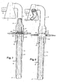
- FIG. 1 shows an overall view in vertical section, of a device for turning the socks in accordance with the invention, in the service of a circular knitting machine for hosiery and with the sock being formed
- FIG. 2 shows the detailed view of a clamp of the device of FIG. 1 to open the elastic band of the sock in the round in the turning station
- FIGS. 3 to 9 represent the different phases of the turning of the sock with the device of FIG. 1.
- a device for turning the socks out of the corresponding treatment machine includes: - A conduit 2, rigidly connected to the outlet of the machine 1, to collect the sock 3 after it has been detached from it, and for are pneumatic transport, with the interposition of a movable tube 5, to a turning station 4 which is connected, downstream, to a pneumatic suction duct 8 with the interposition of a connector 6 and a expulsion bell 7; a turning station 4 with a cylindrical chamber 40 with a vertical axis, connected from above to said connector 6 and from below to an operating cylinder 9.
- a mesh partition 41 Inside said chamber 40 is a mesh partition 41, articulated on its seat 42 with circular opening 43 and provided with a return spring in the horizontal position, that is to say with the opening 43 closed. ; said partition being intended to intercept the sock 3, sucked into the chamber 4, stopping it in the vertical position with the elastic band 30 at the top.
- several (for example four or six) clips 44 are provided, sliding in corresponding horizontal seats 45, arranged radially and angularly equidistant around the chamber and communicating with it to allow, at the end of the centripetal and respectively centrifugal travel of the clamps, to grasp and respectively to open in round the elastic band of the sock which is in the chamber 4.
- each of said clamps 44 is mounted on the movable body 45 of a double-acting pneumatic cylinder 46 and is slaved to a spacer element 47 which is mounted on said body 45 at the rear of the clamp 44 and whose displacement forwards, pneumatically controlled, causes its closure, while a ring spring 48 - with the retractor 47 retracted - causes it to open.
- the bottom of said chamber 4 is provided with an axial circular opening to allow the passage of the aforementioned tube 5 which constitutes the movable body of a pneumatic cylinder 9 aligned with the chamber 40 and with double effect, so as to be able to take two positions , one lowered, in which the foot 50 engages the outlet of the conduit 2 and the head 51 is located in the chamber 40 at a height less than that of the clamps 44 (see Fig. 1) and the other raised , in which the head 51 of the tube 5 passes through the opening 43 of the partition 41 until it reaches the connector 6 (see Fig. 7).
- Said tube 5 has the function of turning over the sock 3 which is in the chamber 40; in fact, in the lowered position of the tube 5, the sock 3 is partially housed hanging inside the tube and, after the elastic band 30 has been opened in the round by the clamps 44 and correctly held thus, the head 51 of the tube 5, by lifting, is able to gradually turn the sock upwards by passing it through the elastic band 30 open.
- annular cup-shaped element 52 which is retained at its base by the flanged end 51 of the tube 5 and which is pushed towards the top by a cylindrical helical spring 53 located below and threaded on the tube 5 itself.
- the operation is as follows.
- the sock 3, once finished and detached from the circular machine 1, is sucked into the conduit 2 and transported to the interior of the chamber 40 where the partition 41, which is lowered, stops it in the vertical position and with the elastic band 30 at the top (see FIG. 3); after which, the clamps 44, preferably closed, are pushed fully into the chamber 40 and then open so as to receive the elastic band 30 at as many points (see FIG. 4); then the clamps 44 are closed and retracted so as to widen, that is to say open in the round, the strip 30 (see FIG. 5).
Abstract
Description
La présente invention concerne un procédé et un dispositif pour retourner les chaussettes hors et à distance de la machine de traitement correspondante.The present invention relates to a method and a device for turning the socks off and at a distance from the corresponding processing machine.
Il est connu qu'au terme de la production avec une machine à tricoter circulaire, les chaussettes pour homme, appelées par la suite "chaussettes", doivent être retournées pour permettre d'autres opérations de finition, comme par exemple la couture invisible de la pointe.
Il est également connu qu'après ladite couture de la pointe, les chaussettes doivent être de nouveau retournées afin de les remettre à l'endroit.
Actuellement, l'opération de retournement est effectuée au moyen d'un dispositif retourneur, uniquement sur les machines à tricoter circulaire pour la bonneterie, sur lesquelles il est fixé coaxialement avec le cylindre des aiguilles et en effectuant le retournement par voie pneumatique.
Mais ce dispositif connu présente certains inconvénients importants. Un premier inconvénient consiste en ce qu'il est monté à l'intérieur de la machine circulaire de sorte qu'il nécessite une adaptation différente en fonction du type de machine auquel il est destiné. Un autre inconvénient dépend du fonctionnement pneumatique qui présente une fiabilité limitée due en partie à la rigidité propre des chaussettes et en partie aux impuretés aspirées inévitablement par la machine qui imposent son arrêt avec une certaine fréquence en diminuant ainsi sa capacité de production.It is known that at the end of production with a circular knitting machine, men's socks, hereinafter called "socks", must be turned over to allow other finishing operations, such as invisible stitching of the point.
It is also known that after said stitching of the tip, the socks must be turned over again in order to put them back on the right side.
Currently, the turning operation is carried out by means of a turning device, only on circular knitting machines for hosiery, on which it is fixed coaxially with the needle cylinder and by turning it pneumatically.
However, this known device has certain significant drawbacks. A first drawback is that it is mounted inside the circular machine so that it requires a different adaptation depending on the type of machine for which it is intended. Another drawback depends on the pneumatic operation which has limited reliability due in part to the inherent rigidity of the socks and in part to the impurities inevitably sucked in by the machine which impose its stopping with a certain frequency thereby reducing its production capacity.
Pour ce qui concerne le retournement après la couture de la pointe, les chaussettes sont encore retournées à la main.Regarding the turning after sewing the point, the socks are still turned by hand.
La présente invention a pour but d'éliminer les inconvénients précités.
Ce résultat a été atteint conformément à l'invention en adoptant un procédé de traitement qui comprend, successivement, les phases suivantes:
- aspirer la chaussette à partir de la machine de traitement correspondante et la transporter hors et à distance de celle-ci, orientée avec la bande élastique en avant;
- arrêter la chaussette ainsi transportée, en position verticale et avec la bande élastique tournée vers le haut;
- saisir de l'extérieur et en plusieurs points la bande élastique de la chaussette ainsi positionnée, et appliquer au niveau desdits points une traction en direction horizontale centrifuge de manière à ouvrir la bande en rond;
- serrer de l'extérieur la bande élastique ainsi ouverte en rond;
- retourner la chaussette sur elle-même en la faisant passer à travers la bande élastique ainsi ouverte et serrée, en procédant de la bande élastique vers et jusqu'à la pointe du pied;
- libérer la bande élastique de la chaussette ainsi retournée et décharger la chaussette orientée avec la pointe du pied en avant.
Et pour mettre en oeuvre ledit procédé, il est prévu d'utiliser:
- des moyens pour extraire la chaussette de la machine de traitement correspondante en l'aspirant dans un conduit qui la transporte jusqu'à une station de retournement placée à distance de la machine et, après le retournement, pour l'envoyer au dispositif de déchargement;
- une station de retournement comprenant: une chambre à axe vertical, avec une cloison interne grillagée, articulée pour intercepter et positionner la chaussette en position verticale et avec la bande élastique en haut; des moyens pour saisir la bande élastique de l'extérieur, lesquels sont soumis à une traction centrifuge pour en effectuer l'ouverture en rond; des moyens externes à la chaussette et soumis à une poussée verticale vers le haut pour serrer toute la bande élastique contre le siège de ladite cloison; un tube de retournement coaxial avec ladite chambre, passant dans ladite tasse et dans l'ouverture de ladite cloison et dans lequel est logée la chaussette, lequel est soumis à un mouvement vertical alternatif dont la course vers le haut, avec la cloison ouverte, provoque le retournement de la chaussette sur elle-même, de la bande élastique jusqu'à la pointe du pied, et son passage simultané à travers l'ouverture de la cloison;
- une cloche d'expulsion de la chaussette retournée et avec la pointe en avant.The present invention aims to eliminate the aforementioned drawbacks.
This result was achieved in accordance with the invention by adopting a treatment method which successively comprises the following phases:
- vacuum the sock from the corresponding treatment machine and transport it out of and away from it, oriented with the elastic band in front;
- stop the sock thus transported, in a vertical position and with the elastic band facing upwards;
- grasp from the outside and at several points the elastic band of the sock thus positioned, and apply at said points a traction in horizontal centrifugal direction so as to open the band in the round;
- tighten the elastic band thus opened in the round from the outside;
- turn the sock over itself by passing it through the elastic band thus open and tight, proceeding from the elastic band to and up to the point of the toe;
- release the elastic band from the sock thus turned over and unload the oriented sock with your toes forward.
And to implement said method, it is planned to use:
- Means for extracting the sock from the corresponding treatment machine by sucking it up in a duct which transports it to a turning station located at a distance from the machine and, after turning, to send it to the unloading device ;
- a turning station comprising: a chamber with a vertical axis, with an internal mesh partition, articulated to intercept and position the sock in a vertical position and with the elastic band at the top; means for gripping the elastic band from the outside, which are subjected to centrifugal traction to open it in the round; means external to the sock and subjected to a vertical upward thrust to clamp the entire elastic band against the seat of said partition; a turning tube coaxial with said chamber, passing through said cup and into the opening of said partition and in which the sock is housed, which is subjected to an alternating vertical movement whose upward stroke, with the partition open, causes the reversal of the sock on itself, from the elastic band to the tip of the foot, and its simultaneous passage through the opening of the partition;
- an expulsion bell of the sock turned upside down and with the point forward.
Avantageusement, lesdits moyens pour saisir la bande élastique de la chaussette sont constitués par plusieurs pinces coplanaires, réparties autour de ladite chambre, angulairement équidistantes et mobiles horizontalement dans la direction radiale avec commande pneumatique.Advantageously, said means for gripping the elastic band of the sock consist of several coplanar clips, distributed around said chamber, angularly equidistant and movable horizontally in the radial direction with pneumatic control.
Lesdits moyens pour assurer le blocage de la bande élastique de la chaussette en position ouverte en rond sont avantageusement constitués par une tasse, enfilée coulissante sur le tube de retournement et sollicitée élastiquement contre la tête de celui-ci.Said means for ensuring the blocking of the elastic band of the sock in the open position in the round are advantageously constituted by a cup, slidably threaded on the turn-up tube and urged elastically against the head thereof.
Les avantages obtenus grâce à la présente invention consistent essentiellement dans le fait que le retournement de la chaussette est effectué à l'extérieur et à distance de la machine de traitement correspondante, aussi bien une machine à tricoter circulaire pour bonneterie qu'une machine à coudre les pointes, et, par conséquent, sans interférer sur son fonctionnement; que le retournement proprement dit est obtenu complètement par voie mécanique en agissant axialement sur toute la circonférence de la chaussette et progressivement sur chaque rang de mailles correspondant; qu'il est possible d'obtenir le retournement correct et fiable et, en outre, en un temps inférieur à celui nécessaire pour la production de la chaussette de la part d'une machine circulaire, de sorte que plusieurs machines circulaires peuvent être servies par un seul dispositif de retournement.The advantages obtained thanks to the present invention essentially consist in the fact that the turning of the sock is carried out outside and at a distance from the corresponding processing machine, both a circular knitting machine for hosiery and a sewing machine. the spikes, and therefore without interfering with its operation; that the upturn itself is obtained completely mechanically by acting axially on the entire circumference of the sock and gradually on each row of stitches corresponding; that it is possible to obtain the correct and reliable turnaround and, moreover, in a time less than that necessary for the production of the sock on the part of a circular machine, so that several circular machines can be served by a single turning device.
Ces avantages et caractéristiques ainsi que d'autres seront plus et mieux compris de chaque homme du métier à la lumière de la description qui va suivre et à l'aide des dessins annexés donnés à titre d'exemplification pratique de l'invention, mais à ne pas considérer dans le sens limitatif; dessins sur lesquels la FIG. 1 représente une vue d'ensemble en coupe verticale, d'un dispositif de retournement des chaussettes conformément à l'invention, au service d'une machine à tricoter circulaire pour bonneterie et avec la chaussette en formation; la FIG. 2 représente la vue détaillée d'une pince du dispositif de la Fig. 1 pour ouvrir en rond la bande élastique de la chaussette dans la station de retournement; les FIG. 3 à 9 représentent les différentes phases du retournement de la chaussette avec le dispositif de la Fig. 1.These advantages and characteristics as well as others will be more and better understood by each person skilled in the art in the light of the description which follows and with the aid of the appended drawings given by way of practical example of the invention, but to do not consider in the limiting sense; drawings in which FIG. 1 shows an overall view in vertical section, of a device for turning the socks in accordance with the invention, in the service of a circular knitting machine for hosiery and with the sock being formed; FIG. 2 shows the detailed view of a clamp of the device of FIG. 1 to open the elastic band of the sock in the round in the turning station; FIGS. 3 to 9 represent the different phases of the turning of the sock with the device of FIG. 1.
De manière plus détaillée et en référence aux Fig. 3 à 9 des dessins annexés, le procédé pour retourner les chaussettes conformément à l'invention comprend les opérations suivantes:
- (a) aspirer la chaussette, qui a été exécutée et détachée de la précédente et de la suivante, à partir de la machine à tricoter circulaire et la transporter dans une station de retournement, placée hors et à distance de ladite machine;
- (b) arrêter la chaussette dans ladite station de retournement, en position verticale et avec la bande élastique vers le haut;
- (c) saisir la bande élastique ainsi positionnée, en plusieurs points angulairement équidistants, et appliquer au niveau desdits points une traction centrifuge de manière à obtenir l'écartement, c'est-à-dire l'ouverture en rond, de la bande élastique;
- (d) serrer de l'extérieur la bande élastique ainsi ouverte en rond, le long de toute sa circonférence;
- (e) retourner la chaussette sur elle-même en la faisant passer à travers la bande élastique ainsi ouverte en rond, en procédant de la bande élastique vers et jusqu'à la pointe du pied;
- (f) libérer la bande élastique de la chaussette ainsi retournée et transporter la chaussette orientée avec la pointe du pied en avant vers une chambre d'évacuation.
- (a) vacuum the sock, which has been run and detached from the previous and the next, from the circular knitting machine and transported to a turning station, placed outside and at a distance from said machine;
- (b) stopping the sock in said turning station, in a vertical position and with the elastic band up;
- (c) grasp the elastic band thus positioned, at several angularly equidistant points, and apply at said points a centrifugal pull so as to obtain the spacing, that is to say the opening in the round, of the elastic band ;
- (d) tighten the elastic band thus opened in the round from the outside, along its entire circumference;
- (e) turn the sock over itself by passing it through the elastic band thus opened in the round, proceeding from the elastic band to and up to the point of the toe;
- (f) release the elastic band from the sock thus turned over and transport the sock oriented with the point of the toe forward towards an evacuation chamber.
Selon une forme de réalisation préférée, un dispositif pour retourner les chaussettes hors de la machine de traitement correspondante suivant ledit procédé, conformément à l'invention et en référence aux Fig. 1 et 2 des dessins annexés, comprend:
- un conduit 2, relié rigidement à la sortie de la machine 1, pour recueillir la chaussette 3 après qu'elle ait été détachée de celle-ci, et pour sont transport pneumatique, avec l'interposition d'un tube mobile 5, jusqu'à une station de retournement 4 qui est reliée, en aval, à un conduit 8 d'aspiration pneumatique avec l'interposition d'un raccord 6 et d'une cloche d'expulsion 7;
- une station de retournement 4 avec une chambre cylindrique 40 à axe vertical, reliée par le haut audit raccord 6 et par le bas à un cylindre opérateur 9.
A l'intérieur de ladite chambre 40 se trouve une cloison grillagée 41, articulée sur son siège 42 avec ouverture circulaire 43 et pourvue d'un ressort de rappel dans la position horizontale, c'est-à-dire avec l'ouverture 43 fermée; ladite cloison étant destinée à intercepter la chaussette 3, aspirée dans la chambre 4, en l'arrêtant dans la position verticale avec la bande élastique 30 en haut.
A l'extérieur de ladite chambre 4 et à une hauteur à peine inférieure à celle de ladite cloison 41, plusieurs (par exemple quatre ou six) pinces 44 sont prévues, coulissantes dansd des sièges horizontaux 45 correspondants, disposés radialement et angulairement équidistants autour de la chambre et communicant avec celle-ci pour permettre, en fin de course centripète et respectivement centrifuge des pinces, de saisir et respectivement d'ouvrir en rond la bande élastique de la chaussette qui se trouve dans la chambre 4.
Conformément à l'invention, chacune desdites pinces 44 est montée sur le corps mobile 45 d'un cylindre pneumatique 46 à double effet et est asservie à un elément écarteur 47 qui est monté sur ledit corps 45 à l'arrière de la pince 44 et dont le déplacement en avant, à commande pneumatique, en provoque la fermeture, alors qu'un ressort à anneau 48 - avec l'écarteur 47 escamoté - en provoque l'ouverture.
Le fond de ladite chambre 4 est pourvu d'une ouverture circulaire axiale pour permettre le passage du tube 5 précité qui constitue le corps mobile d'un cylindre pneumatique 9 aligné avec la chambre 40 et à double effet, de manière à pouvoir prendre deux positions, l'une abaissée, dans laquelle le pied 50 s'engage sur la sortie du conduit 2 et la tête 51 se trouve dans la chambre 40 à une hauteur inférieure à celle des pinces 44 (voir Fig. 1) et l'autre élevée, dans laquelle la tête 51 du tube 5 passe à travers l'ouverture 43 de la cloison 41 jusqu'à atteindre le raccord 6 (voir Fig. 7).
Ledit tube 5 a pour fonction de retourner la chaussette 3 qui se trouve dans la chambre 40; en effet, dans la position abaissée du tube 5, la chaussette 3 se trouve en partie logée pendante à l'intérieur du tube et, après que la bande élastique 30 a été ouverte en rond par les pinces 44 et correctement maintenue ainsi, la tête 51 du tube 5, en se soulevant, est en mesure de retourner progressivement la chaussette vers le haut en la faisant passer à travers la bande élastique 30 ouverte.
Dans le but de bloquer la bande élastique 30 pendant le retournement de la chaussette 3, il est prévu, conformément à l'invention, de monter sur l'extrémité supérieure du tube 5 un élément annulaire en forme de tasse 52 qui est retenue au niveau de sa base par l'extrémité a bride 51 du tube 5 et qui est poussée vers le haut par un ressort à hélice cylindrique 53 situé au-dessous et enfilé sur le tube 5 lui-même.
Conformément à l'invention, il est prévu que le conduit 2 puisse amener séparément à la chambre 40 les chaussettes 3 produites par plusieurs machine à tricoter circulaire 1.According to a preferred embodiment, a device for turning the socks out of the corresponding treatment machine according to said method, in accordance with the invention and with reference to FIGS. 1 and 2 of the accompanying drawings, includes:
- A
a
Inside said
Outside said
According to the invention, each of said
The bottom of
Said
In order to block the
According to the invention, provision is made for the
Le fonctionnement est le suivant. La chaussette 3, une fois terminée et détachée de la machine circulaire 1, est aspirée dans le conduit 2 et transportée jusqu'à l'intérieur de la chambre 40 où la cloison 41, qui est abaissée, l'arrête en position verticale et avec la bande élastique 30 en haut (voir Fig. 3); après quoi, les pinces 44, de préférences fermées, sont poussées à fond dans la chambre 40 et ensuite ouvertes de manière à recevoir la bande élastique 30 en autant de points (voir Fig. 4); ensuite les pinces 44 sont refermées et escamotées de manière à élargir, c'est-à-dire à ouvrir en rond, la bande 30 (voir Fig. 5). A ce stade, en actionnant le cylindre 9 par l'intermédiaire de l'entrée 91, le tube de retournement 5 se soulève et, après le blocage de la bande 30 contre le siège 42 de la cloison 41 par la tasse 52 sous l'effet de la poussée du ressort 53, l'extrémité à bride 51 du tube 5, en poursuivant sa course vers le haut, soulève la cloison 41 et entra ne vers le haut la chaussette 3 en la retournant (voir Fig. 6). Une fois le retournement terminé, en actionnant le cylindre 9 au moyen de l'entrée 92, le tube 5 revient en arrière et, durant sa course de descente, rabaisse la tasse 52 (voir Fig. 7); enfin, en ouvrant le pinces 44, la chaussette retournée 3′ est libérée et aspirée dans la cloche 7 d'expulsion, et la cloison 41 redescend immédiatement en refermant l'ouverture 43 (voir Fig. 8).The operation is as follows. The
Claims (8)
- des moyens pour extraire la chaussette (3) de la machine correspondante (1) en l'aspirant dans un conduit (2) qui la transporte jusqu'à une station de retournement (4) placée à distance de la machine (1) et, après le retournement, pour l'envoyer au dispositif de déchargement;
- une station de retournement (4) comprenant: une chambre (40) à axe vertical, avec une cloison grillagée (41) articulée, pour intercepter et positionner la chaussette (3) en position verticale et avec la bande élastique (30) en haut; des moyens pour saisir la bande élastique (30) de l'extérieur et effectuer son ouverture en rond; des moyens en forme de tasse (52) pour bloquer la bande élastique (30) ainsi ouverte en rond; un tube de retournement (5) coaxial avec la chambre (40), passant dans ladite tasse (52) et dans l'ouverture (43) de ladite cloison (41), lequel est asservi à un cylindre pneumatique (9) à double effet, en alignement avec la chambre (40) et dans lequel (5) la chaussette (3) se trouve en partie logée pendante de manière à ce que la course vers le haut du tube (5) provoque l'actionnement de la tasse (52), l'ouverture de la cloison (41) et le retournement de la chaussette (3) sur elle-même, de la bande élastique jusqu'à la pointe du pied, en la faisant passer à travers l'ouverture (43) de la cloison (41);
- une cloche (7) d'expulsion de la chaussette (3′) retournée et avec la pointe en avant.3) Device for turning the socks out of the corresponding treatment machine according to the method according to claims 1 and 2, characterized in that it comprises:
means for extracting the sock (3) from the corresponding machine (1) by sucking it up in a conduit (2) which transports it to a turning station (4) placed at a distance from the machine (1) and , after turning, to send it to the unloading device;
- a turning station (4) comprising: a chamber (40) with vertical axis, with a hinged mesh partition (41), for intercepting and positioning the sock (3) in the vertical position and with the elastic band (30) at the top ; means for gripping the elastic band (30) from the outside and opening it in the round; cup-shaped means (52) for locking the elastic band (30) thus opened in the round; a turning tube (5) coaxial with the chamber (40), passing through said cup (52) and into the opening (43) of said partition (41), which is controlled by a double-acting pneumatic cylinder (9) , in alignment with the chamber (40) and in which (5) the sock (3) is partially housed hanging so that the upward stroke of the tube (5) causes the actuation of the cup (52 ), the opening of the partition (41) and the turning of the sock (3) on itself, from the elastic band to the ball of the foot, by passing it through the opening (43) of the partition (41);
- a bell (7) for expelling the sock (3 ′) turned upside down and with the tip forward.
Applications Claiming Priority (2)
| Application Number | Priority Date | Filing Date | Title |
|---|---|---|---|
| IT9560A IT1236086B (en) | 1989-11-03 | 1989-11-03 | METHOD AND DEVICE FOR REVERSING MEN'S SOCKS OUT OF THE RELEVANT OPERATING MACHINE |
| IT956089 | 1989-11-03 |
Publications (2)
| Publication Number | Publication Date |
|---|---|
| EP0430900A2 true EP0430900A2 (en) | 1991-06-05 |
| EP0430900A3 EP0430900A3 (en) | 1992-03-04 |
Family
ID=11132208
Family Applications (1)
| Application Number | Title | Priority Date | Filing Date |
|---|---|---|---|
| EP19900830500 Withdrawn EP0430900A3 (en) | 1989-11-03 | 1990-10-30 | Method and apparatus for turning socks inside out outside the corresponding processing machine |
Country Status (7)
| Country | Link |
|---|---|
| US (1) | US5127558A (en) |
| EP (1) | EP0430900A3 (en) |
| JP (1) | JPH03260161A (en) |
| KR (1) | KR910009990A (en) |
| CA (1) | CA2028356A1 (en) |
| CZ (1) | CZ528390A3 (en) |
| IT (1) | IT1236086B (en) |
Cited By (3)
| Publication number | Priority date | Publication date | Assignee | Title |
|---|---|---|---|---|
| EP0526429A2 (en) * | 1991-07-31 | 1993-02-03 | Francesco Turini | Pneumatic suction apparatus for tensioning, reversing and conveying away a tubular knitted article |
| WO1999055947A1 (en) * | 1998-04-24 | 1999-11-04 | Giuseppe De Giovanni | Device for turning tubular textile products inside out |
| WO2003018903A1 (en) * | 2001-08-28 | 2003-03-06 | Golden Lady S.P.A. | Device and method for opening the edge of a tubular knitted article or similar |
Families Citing this family (10)
| Publication number | Priority date | Publication date | Assignee | Title |
|---|---|---|---|---|
| US5507421A (en) * | 1993-12-06 | 1996-04-16 | Keeton; Herbert | Turn and cut machine for reverse-folding tubular textile material and methods of operation |
| CZ103395A3 (en) * | 1994-04-26 | 1995-11-15 | Sangiacomo Spa | Method of transferring stockings from a stocking knitting machine to a sewing machine and apparatus for taking off and transfer of stockings |
| US5699942A (en) * | 1995-07-21 | 1997-12-23 | Sara Lee Corporation | Automatic sleeve invertor |
| CA2259812A1 (en) * | 1999-01-20 | 2000-07-20 | Andre M. Drisdelle | Sock turning device |
| US6638202B2 (en) | 2001-04-20 | 2003-10-28 | Autotex, Sa | Bag turning device |
| US6519980B1 (en) | 2002-04-03 | 2003-02-18 | Sara Lee Corporation | Hosiery dewrinkling system and method for circular knitting machines |
| CN103451847B (en) * | 2013-08-27 | 2015-06-24 | 海宁阳光袜业有限公司 | Full-automatic hosiery machine |
| EP3715511B1 (en) * | 2019-03-26 | 2022-08-31 | Stäubli Italia S.p.A. | Method and device for reversing a tubular knitted article in a circular knitting machine |
| CN111876980B (en) * | 2020-07-16 | 2022-07-12 | 安徽中科智能高技术有限责任公司 | Automatic turn-over device for long-roll sock leg and control method |
| CN113862889B (en) * | 2021-11-03 | 2022-11-11 | 绍兴绿地针织有限公司 | Hosiery knitter convenient to different model socks ejection of compact |
Citations (7)
| Publication number | Priority date | Publication date | Assignee | Title |
|---|---|---|---|---|
| GB1055701A (en) * | 1962-08-30 | 1967-01-18 | Lewis Henry Colton | An improved suction take down apparatus for use with knitting machines |
| FR1523778A (en) * | 1967-05-19 | 1968-05-03 | Feinstrumpfwerke Esda Veb | Device for pneumatic turning of tubular raw articles, for example circular knitting ladies' bottom |
| DE1907167A1 (en) * | 1968-03-09 | 1969-10-02 | Arrigo Micheletti | Pneumatic device for stretching out socks and similar items |
| GB1186384A (en) * | 1966-05-20 | 1970-04-02 | Francesco Lonati | Device for Turning a Tubular Knitted Piece Inside Out |
| FR2130836A5 (en) * | 1971-03-23 | 1972-11-10 | Heliot Maurice Ets | Handling device - for feeding stockings onto a former comprises clamps carried on endless conveyor |
| US3738123A (en) * | 1969-07-14 | 1973-06-12 | Solis Sil | Pneumatic knit fabric tensioning devices for use with circular knitting machines |
| US4487546A (en) * | 1981-08-05 | 1984-12-11 | Savio & C. S.P.A. | Device for transferring tubular fabrics from support hangers to a rigid body and inverting the fabric |
Family Cites Families (17)
| Publication number | Priority date | Publication date | Assignee | Title |
|---|---|---|---|---|
| DE243948C (en) * | ||||
| US2657841A (en) * | 1950-07-25 | 1953-11-03 | Charnwood Engineering Company | Apparatus for turning stockings and the like |
| US2999618A (en) * | 1959-08-06 | 1961-09-12 | Marvel Specialty | Hosiery inspecting, stacking and bundling apparatus |
| DE1585301A1 (en) * | 1964-04-22 | 1970-04-09 | Werner Roessler | Method for aligning and longitudinally stacking socks knitted on the circular knitting machine |
| US3941285A (en) * | 1974-08-30 | 1976-03-02 | Americal Corporation | Apparatus for producing panty hose |
| US3949913A (en) * | 1974-11-26 | 1976-04-13 | Marvel Specialty Company | Hosiery handling system with u-shaped form |
| GB2029470B (en) * | 1978-08-18 | 1982-10-20 | Ogm Trading Aps | Device and a method for everting tubular garment portions and like |
| US4281781A (en) * | 1979-01-15 | 1981-08-04 | Pope William H | Hose everting method and apparatus therefor |
| GB2057527B (en) * | 1979-08-30 | 1983-03-30 | Safeguard Ltd | Apparatus for turning trouser legs inside out |
| FR2475591A1 (en) * | 1980-02-08 | 1981-08-14 | Inst Textile De France | CONTINUOUS METHOD AND SLEEVE FOLDING DEVICE FOLDED |
| JPS59160492A (en) * | 1982-11-16 | 1984-09-11 | 中平 智丈 | Automatic apparatus for turning back, cutting and stitching continuously knitted sock cloth |
| IT1205383B (en) * | 1983-04-11 | 1989-03-15 | Rosso Ind Spa | STOCKING DEVICE |
| JPS6014879A (en) * | 1983-07-06 | 1985-01-25 | 住友ゴム工業株式会社 | Composition for covering golf ball |
| IT1176349B (en) * | 1984-06-29 | 1987-08-18 | Savio Spa | DEVICE AND DRAWING PROCEDURE WITH REVERSE FOR CIRCULAR KNITTING MACHINES |
| JPS6194592A (en) * | 1984-10-12 | 1986-05-13 | Matsushita Electric Works Ltd | Damping circuit for stepping motor |
| SU1234482A1 (en) * | 1984-12-28 | 1986-05-30 | Центральный Ордена Трудового Красного Знамени Научно-Исследовательский Институт Швейной Промышленности | Device for turning out tubular articles |
| JPS6461565A (en) * | 1987-08-28 | 1989-03-08 | Terumitsuku Kk | Reversal method and apparatus of socks in socks toe sewing machine |
-
1989
- 1989-11-03 IT IT9560A patent/IT1236086B/en active IP Right Grant
-
1990
- 1990-10-19 KR KR1019900016723A patent/KR910009990A/en not_active Application Discontinuation
- 1990-10-23 CA CA002028356A patent/CA2028356A1/en not_active Abandoned
- 1990-10-29 CZ CS905283A patent/CZ528390A3/en unknown
- 1990-10-30 EP EP19900830500 patent/EP0430900A3/en not_active Withdrawn
- 1990-10-30 US US07/605,927 patent/US5127558A/en not_active Expired - Fee Related
- 1990-11-02 JP JP2298777A patent/JPH03260161A/en active Pending
Patent Citations (7)
| Publication number | Priority date | Publication date | Assignee | Title |
|---|---|---|---|---|
| GB1055701A (en) * | 1962-08-30 | 1967-01-18 | Lewis Henry Colton | An improved suction take down apparatus for use with knitting machines |
| GB1186384A (en) * | 1966-05-20 | 1970-04-02 | Francesco Lonati | Device for Turning a Tubular Knitted Piece Inside Out |
| FR1523778A (en) * | 1967-05-19 | 1968-05-03 | Feinstrumpfwerke Esda Veb | Device for pneumatic turning of tubular raw articles, for example circular knitting ladies' bottom |
| DE1907167A1 (en) * | 1968-03-09 | 1969-10-02 | Arrigo Micheletti | Pneumatic device for stretching out socks and similar items |
| US3738123A (en) * | 1969-07-14 | 1973-06-12 | Solis Sil | Pneumatic knit fabric tensioning devices for use with circular knitting machines |
| FR2130836A5 (en) * | 1971-03-23 | 1972-11-10 | Heliot Maurice Ets | Handling device - for feeding stockings onto a former comprises clamps carried on endless conveyor |
| US4487546A (en) * | 1981-08-05 | 1984-12-11 | Savio & C. S.P.A. | Device for transferring tubular fabrics from support hangers to a rigid body and inverting the fabric |
Cited By (5)
| Publication number | Priority date | Publication date | Assignee | Title |
|---|---|---|---|---|
| EP0526429A2 (en) * | 1991-07-31 | 1993-02-03 | Francesco Turini | Pneumatic suction apparatus for tensioning, reversing and conveying away a tubular knitted article |
| EP0526429A3 (en) * | 1991-07-31 | 1993-06-16 | Francesco Turini | Pneumatic suction apparatus for tensioning, reversing and conveying away a tubular knitted article |
| WO1999055947A1 (en) * | 1998-04-24 | 1999-11-04 | Giuseppe De Giovanni | Device for turning tubular textile products inside out |
| US6296159B1 (en) | 1998-04-24 | 2001-10-02 | Giuseppe De Giovanni | Device for turning tubular textile products inside out |
| WO2003018903A1 (en) * | 2001-08-28 | 2003-03-06 | Golden Lady S.P.A. | Device and method for opening the edge of a tubular knitted article or similar |
Also Published As
| Publication number | Publication date |
|---|---|
| CZ528390A3 (en) | 1993-12-15 |
| KR910009990A (en) | 1991-06-28 |
| US5127558A (en) | 1992-07-07 |
| IT8909560A0 (en) | 1989-11-03 |
| EP0430900A3 (en) | 1992-03-04 |
| JPH03260161A (en) | 1991-11-20 |
| CA2028356A1 (en) | 1991-05-04 |
| IT1236086B (en) | 1992-12-22 |
Similar Documents
| Publication | Publication Date | Title |
|---|---|---|
| EP0430900A2 (en) | Method and apparatus for turning socks inside out outside the corresponding processing machine | |
| CA2961308C (en) | Device for transferring moving parts | |
| FR2715642A1 (en) | Device for rotating parts lying flat during their advance. | |
| EP0818570B1 (en) | Apparatus for collecting and moving tubular products | |
| FR2503105A1 (en) | METHOD AND DEVICE FOR THE HANDLING OF HOSES | |
| EP0584050B1 (en) | Method and apparatus for transfering a panty from a panty sewing machine to a toe closing sewing machine | |
| FR2553969A1 (en) | Device for felling trees | |
| EP0654554B1 (en) | Method and apparatus for the automatic loading of a machine for sewing gussets on knitted garments of the "pantyhose" type | |
| FR2571070A1 (en) | AUTOMATIC MACHINE FOR TURNING BOTTOMS WITH MOBILE ROLLERS. | |
| FR2566635A1 (en) | Device for automatic transfer of a shoe between machines | |
| EP1367167B1 (en) | Device and apparatus for transferring tubular knitted articles between a stockpile station and at least one blank of a forming or sewing or ironing station | |
| CH467176A (en) | Device for detaching tire beads from a wheel rim | |
| FR3106586A1 (en) | Device for automatically feeding a robot for threading socks oriented in the right direction on a former without stopping by trays filled with loose socks | |
| CH496132A (en) | Method for automatically closing the end of a tubular fabric article and apparatus for carrying out this method | |
| FR2766334A1 (en) | Broccoli trimming machine for separating florets | |
| EP0882829B1 (en) | Apparatus for the spreading of an end portion of a tubular article | |
| EP0887453A1 (en) | Apparatus and method for positioning textile articles | |
| EP0299036A1 (en) | Method and device for taking one by one bags from a pile of bags and for placing them in a predetermined position | |
| FR2520339A1 (en) | DEVICE FOR THE CONTINUOUS PRODUCTION AND DEPOSITION OF YARN LOOPS | |
| FR2598336A1 (en) | MANIPULATOR FOR THE AUTOMATIC FEEDING OF MACHINES FOR THE CENTRIFUGATION OF WIRE REELS | |
| FR2702694A1 (en) | Device for loading and unloading lapping and honing machines. | |
| FR2492852A1 (en) | MOUNTING DEVICE SWIVELING A PIN, IN PARTICULAR FOR DEVICE FOR SPUNNING A WIRE ENVELOPE | |
| EP0146435B1 (en) | Device for turning the pages of a book | |
| EP0268537A1 (en) | Device for the continuous manufacture of sausages and similar products from the conception of the sausages to the tying of their extremities | |
| FR2643348A1 (en) | Device for conveying components with or without turning-over with a view to stacking them in at least one container |
Legal Events
| Date | Code | Title | Description |
|---|---|---|---|
| PUAI | Public reference made under article 153(3) epc to a published international application that has entered the european phase |
Free format text: ORIGINAL CODE: 0009012 |
|
| AK | Designated contracting states |
Kind code of ref document: A2 Designated state(s): AT BE CH DE DK ES FR GB GR IT LI NL SE |
|
| RBV | Designated contracting states (corrected) |
Designated state(s): DE ES FR GB IT |
|
| PUAL | Search report despatched |
Free format text: ORIGINAL CODE: 0009013 |
|
| AK | Designated contracting states |
Kind code of ref document: A3 Designated state(s): AT BE CH DE DK ES FR GB GR IT LI NL SE |
|
| 17P | Request for examination filed |
Effective date: 19920427 |
|
| STAA | Information on the status of an ep patent application or granted ep patent |
Free format text: STATUS: THE APPLICATION IS DEEMED TO BE WITHDRAWN |
|
| 18D | Application deemed to be withdrawn |
Effective date: 19940503 |