EP0136040A2 - Rundes ummanteltes elektrisches Kabel - Google Patents
Rundes ummanteltes elektrisches Kabel Download PDFInfo
- Publication number
- EP0136040A2 EP0136040A2 EP84305602A EP84305602A EP0136040A2 EP 0136040 A2 EP0136040 A2 EP 0136040A2 EP 84305602 A EP84305602 A EP 84305602A EP 84305602 A EP84305602 A EP 84305602A EP 0136040 A2 EP0136040 A2 EP 0136040A2
- Authority
- EP
- European Patent Office
- Prior art keywords
- cable
- conductors
- insulation
- electrical cable
- round
- Prior art date
- Legal status (The legal status is an assumption and is not a legal conclusion. Google has not performed a legal analysis and makes no representation as to the accuracy of the status listed.)
- Withdrawn
Links
- 239000004020 conductor Substances 0.000 claims abstract description 47
- 238000009413 insulation Methods 0.000 claims abstract description 41
- 238000006073 displacement reaction Methods 0.000 description 7
- 239000000463 material Substances 0.000 description 4
- 229920000915 polyvinyl chloride Polymers 0.000 description 3
- 239000004800 polyvinyl chloride Substances 0.000 description 3
- 238000004519 manufacturing process Methods 0.000 description 2
- 238000005065 mining Methods 0.000 description 2
- 239000004698 Polyethylene Substances 0.000 description 1
- 239000004809 Teflon Substances 0.000 description 1
- 229920006362 Teflon® Polymers 0.000 description 1
- 239000000853 adhesive Substances 0.000 description 1
- 230000001070 adhesive effect Effects 0.000 description 1
- 238000010276 construction Methods 0.000 description 1
- 238000013500 data storage Methods 0.000 description 1
- 238000000034 method Methods 0.000 description 1
- 238000012986 modification Methods 0.000 description 1
- 230000004048 modification Effects 0.000 description 1
- 230000000737 periodic effect Effects 0.000 description 1
- -1 polyethylene Polymers 0.000 description 1
- 229920000573 polyethylene Polymers 0.000 description 1
- 238000002360 preparation method Methods 0.000 description 1
- 238000000926 separation method Methods 0.000 description 1
Images

Classifications
-
- H—ELECTRICITY
- H01—ELECTRIC ELEMENTS
- H01B—CABLES; CONDUCTORS; INSULATORS; SELECTION OF MATERIALS FOR THEIR CONDUCTIVE, INSULATING OR DIELECTRIC PROPERTIES
- H01B7/00—Insulated conductors or cables characterised by their form
- H01B7/17—Protection against damage caused by external factors, e.g. sheaths or armouring
- H01B7/18—Protection against damage caused by wear, mechanical force or pressure; Sheaths; Armouring
-
- H—ELECTRICITY
- H01—ELECTRIC ELEMENTS
- H01B—CABLES; CONDUCTORS; INSULATORS; SELECTION OF MATERIALS FOR THEIR CONDUCTIVE, INSULATING OR DIELECTRIC PROPERTIES
- H01B7/00—Insulated conductors or cables characterised by their form
- H01B7/08—Flat or ribbon cables
- H01B7/0892—Flat or ribbon cables incorporated in a cable of non-flat configuration
-
- H—ELECTRICITY
- H01—ELECTRIC ELEMENTS
- H01B—CABLES; CONDUCTORS; INSULATORS; SELECTION OF MATERIALS FOR THEIR CONDUCTIVE, INSULATING OR DIELECTRIC PROPERTIES
- H01B7/00—Insulated conductors or cables characterised by their form
- H01B7/08—Flat or ribbon cables
- H01B7/0853—Juxtaposed parallel wires, fixed to each other without a support layer
Definitions
- the present invention relates generally to electrical cable and more particularly to round jacketed electrical cable, particularly with facility for mass termination.
- Electrical cable is utilized to interconnect telecommunication equipments in order to complete a data or voice link.
- these equipments include telephones, computers, data storage units, facsimile devices and combinations of these equipments.
- a "round jacketed" cable has been used for this purpose.
- a round jacketed cable presents advantages in terms of ease of routing, reduced space required, and mechanical flexibility in all directions.
- These round jacketed cables are usually composed of individual wires or separate twisted wire pairs which must be individually terminated. Individual termination of these conductors is a very time consuming process.
- Ribbon cable has also been utilized in the telecommunications field.
- a ribbon cable a plurality of insulated conductors are joined together in a known spaced relationship in a single plane.
- An example of this type of ribbon cable is Scotchflex 3365 cable, manufactured by Minnesota Mining and Manufacturing Company, Saint Paul, Minnesota. Ribbon cable offers the ability to mass terminate the cable using insulation displacement connectors as well as offering a large number of conductors in a small space.
- This cable which combines the mass terminability aspects of ribbon cable with the geometric advantages of a round jacketed cable.
- This cable is marketed under the tradename "Okiflex” by Oki Electric Cable Company, Ltd.
- This cable consists of a ribbon cable which has been spirally wrapped to form a generally circular cross-section and then jacketed to form a round jacketed cable. While this cable can be mass terminated, a substantial amount of jacketed material must be stripped back from the termination point in order for the ribbon cable to be "unwound" from the spiral and to lay reasonably flat for mass termination.
- the present invention provides a round jacketed electrical cable having a plurality of longitudinally extending conductors with insulation encasing each of the conductors.
- the conductors have bonded longitudinal portions in which the insulation of the conductors are bonded together forming a unitary ribbon cable and has separated longitudinal portions in which the insulation of the conductors are laterally separate.
- the insulation in the bonded longitudinal portions form lateral alignment grooves.
- the ribbon cable in the bonded longitudinal portions is folded over onto itself forming a plurality of pleats.
- a jacket surrounds the pleated ribbon cable forming an electrical cable which has physical characteristics of being round and flexible as well as being mass terminable.
- the conductors are of uniform cross-sectional area.
- the bonded longitudinal portions are equally spaced and lie in a single plane.
- the plurality of pleats are wider at the center of the ribbon cable than at the edges of the ribbon cable.
- an electrical conductor is interposed between the pleated ribbon cable and the jacket forming a shielded round jacketed mass terminable electrical cable.
- the folding of the ribbon cable into pleats offers a distinct advantage in use over the spirally wrapped "Okiflex" cable.
- the amount of (length of) jacket which must be stripped back from the termination point is much less for the cable of the present invention than the spirally wrapped cable. In fact, it is estimated that only one-half of unjacketed cable from the termination point is required to be stripped as compared to a spirally wrapped round jacketed ribbon cable.
- the cross-sectional area of the spirally wrapped cable is generally larger than the cable of the present invention because the spirally wrapped cable is loosely wrapped to account for termination stripping length. If wound as tightly, the spirally wrapped cable would have an even greater termination stripping length.
- the cable of the present invention is one which can be made flexible in all directions in a shorter distance from the termination point, allows a much neater appearance and is less susceptible to damage from external objects while still providing all of the advantages of a round jacketed ribbon cable.
- the individual conductors of the ribbon cable are slit apart periodically, or joined periodically, depending upon your perspective, within the cable.
- the periodicity of bonded longitudinal portions with separated longitudinal portions provides mass terminability at closely spaced portions of cable where the individual conductors are not separated, and aids in maintaining cable flexibility.
- FIG. 1 illustrates a ribbon cable 10 from which the rounded jacketed electrical cable of the present invention may be constructed.
- the ribbon cable 10 comprises a plurality of insulation encased conductors 12 with a known transverse spaced relationship lying in a single plane.
- the ribbon cable 10 has periodic bonded longitudinal portions 14 interspersed with separated longitudinal portions 16.
- the insulation encased conductors 12 maintain their transversely fixed spaced relationship through the bonding of the insulation encased conductors 12 to each other.
- the ribbon cable 10 acts and looks like a standard ribbon cable such as Scotchflex 3365 cable, manufactured by Minnesota Mining and Manufacturing Company, Saint Paul, Minnesota.
- each bonded longitudinal portion 14 is at least as long as the length required to connect to the insulation displacement connector being utilized.
- a termination area of Lwo-thirds of one inch (16.9 millimeters) is required.
- each of the bonded longitudinal portions 14 are at least two-thirds of one inch long (16.9 millimeters) enabling a mass termination at each bonded longitudinal portion 14.
- each separated longitudinal portion 16 some or all of the insulation encased conductors 12 are separated from each other. Such separation is done to enable the completed round jacketed electrical cable to be more flexible when the ribbon cable 10 is subsequently pleated and encased in a jacket.
- the separated longitudinal portions 16 can be achieved either by separating an already joined ribbon cable 10 as in the case of slitting insulation encased conductors in the Scotchflex 3365 cable, or by bonding, either by use of an adhesive or by thermal bonding, separate insulation encased conductors 12 to form the bonded longitudinal portions 14.
- the bonded longitudinal portions 14 and separated longitudinal portions 16 are formed by taking separate insulation encased conductors 12 and utilizing a separate support structure to form the bonded longitudinal section 14.
- each insulation encased conductor 12 are of uniform cross-sectional area. Typically such conductors are in the range of from 24 AWG to 30 AWG.
- a typical material which can be utilized for the insulation covering the insulation encased conductors 12 is polyvinylchloride.
- the bonded longitudinal portions 14 contain longitudinal grooves providing lateral alignment which enable the insulation displacement connectors to be aligned with each individual insulation encased conductor 12 in order to properly mass terminate the ribbon cable'10.
- FIG 2 shows a cross-section of a ribbon cable 10 of Figure 1 taken along Section Line 2-2.
- Each insulation encased conductor 12 contains a conductor 18 surrounded by insulation 20.
- Figure 2 which is a cross-section taken across a bonded longitudinal portion 14, that all of the insulation encased conductors 12 are held together in a transversely fixed spaced relationship enabling easy mass termination.
- the insulation 20 encasing conductors 18 form a plurality of ridges over the conductors 18, creating a plurality of alignment grooves 22 to enable easy alignment of the insulation displacement connectors.
- Figure 3 is a cross-section of the same ribbon cable 10 taken along a Section Line 3-3 during a separated longitudinal portion 16.
- a plurality of conductors 18 are encased in insulation 20.
- insulation encased conductors 12 are separated from their adjacent counterpart.
- FIG 4 illustrates the ribbon cable 10 of Figure 1 which has been pleated and covered with a jacket 24 to form a round jacketed electrical cable 26 of the present invention.
- the ribbon cable 10 has been pleated by folding the ribbon cable 10 back and forth upon itself as illustrated in Figure 4 to form a compact structure of approximately circular cross-section.
- the pleated ribbon cable 10 is then covered by jacket 24 maintaining the circular cross-section.
- An example of a material suitable for use as a jacket 24 is polyvinylchloride, polyethylene or Teflon (a registered Trademark of DuPont).
- polyvinylchloride is preferred as material for jacket 24.
- the interior pleats 28 are wider than the edge pleats 30. The variation in widths of the interior pleats 28 and edge pleats 30 enable the pleated ribbon cable 10 to more closely resemble a circular cross-section.
- the round jacketed electrical cable 26 illustrated in Figure 5 also contains a pleated ribbon cable 10 to form a circular cross-section and is also encased within a jacket 24. Again, interior pleats 28 are preferred to be wider than edge pleats 30 to enable a more complete circular cross-section.
- the round jacketed electrical cable 26 of Figure 5 contains a conductive shield 32 interposed between the pleated ribbon cable 10 and jacket 24. With the use of a suitable conductive shield 32, a round jacketed mass terminable electrical cable can be constructed which is also shielded and flexible.
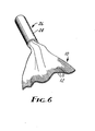
- FIG. 6 illustrates the round jacketed electrical cable 26 being unfolded to enable the ribbon cable 10 to be mass terminated.
- ribbon cable 10 has been pleated and contained within jacket 24.
- Jacket 24 has been stripped away from the end of the round jacketed electrical cable 26 so that ribbon cable 10 may be unfolded to conform to a single plane so that the ribbon cable 10 could be mass terminated using standard available insulation displacement connectors.
- the amount of jacket 24 which must be stripped from the end of the round jacketed electrical cable 26 depends upon the manner in which the ribbon cable 10 is folded within jacket 24.
- Prior art cables have utilized a spiral wrap in which the ribbon cable 10 is rolled up to form a circular cross-section.
- FIG. 6 illustrates that with the pleating of the ribbon cable 10 in the round jacketed electrical ribbon cable 26 of the present invention that only half as much jacket 24 need to be stripped back to enable the ribbon cable 10 to lie flat.
- the edge insulation encased conductors 12 lie at the outer extremities of the folded ribbon cable 10. As the unfolding occurs the cable can be unfolded from both sides of the ribbon cable 10 at once, enabling the ribbon cable 10 of the present invention to lie flat in half or less of the longitudinal space required in prior art spirally wound cables.
Landscapes
- Insulated Conductors (AREA)
- Communication Cables (AREA)
Applications Claiming Priority (2)
| Application Number | Priority Date | Filing Date | Title |
|---|---|---|---|
| US52799883A | 1983-08-31 | 1983-08-31 | |
| US527998 | 1983-08-31 |
Publications (2)
| Publication Number | Publication Date |
|---|---|
| EP0136040A2 true EP0136040A2 (de) | 1985-04-03 |
| EP0136040A3 EP0136040A3 (de) | 1987-04-22 |
Family
ID=24103838
Family Applications (1)
| Application Number | Title | Priority Date | Filing Date |
|---|---|---|---|
| EP84305602A Withdrawn EP0136040A3 (de) | 1983-08-31 | 1984-08-17 | Rundes ummanteltes elektrisches Kabel |
Country Status (4)
| Country | Link |
|---|---|
| EP (1) | EP0136040A3 (de) |
| JP (1) | JPS6062008A (de) |
| KR (1) | KR850001624A (de) |
| BR (1) | BR8404173A (de) |
Cited By (7)
| Publication number | Priority date | Publication date | Assignee | Title |
|---|---|---|---|---|
| GB2176926A (en) * | 1985-06-22 | 1987-01-07 | Kabelmetal Electro Gmbh | Electric cable |
| DE3721085A1 (de) * | 1987-06-26 | 1989-01-05 | Kabelmetal Electro Gmbh | Verfahren zur herstellung eines elektrischen kabels |
| EP0272211A3 (de) * | 1986-12-18 | 1989-07-05 | Maillefer S.A. | Electrisches Kabel, Kabelherstellungsverfahren und Einrichtung zur Durchführung des Verfahrens |
| WO2003052772A1 (en) | 2001-12-18 | 2003-06-26 | The Ludlow Company Lp | Flexible interconnect cable with ribbonized ends and method of manufacturing |
| US8013252B2 (en) | 2001-03-30 | 2011-09-06 | Larry Daane | Flexible interconnect cable with ribbonized ends |
| EP2728588A1 (de) * | 2009-06-19 | 2014-05-07 | 3M Innovative Properties Company | Abgeschirmtes stromkabel und verfahren zu seiner herstellung |
| US9685259B2 (en) | 2009-06-19 | 2017-06-20 | 3M Innovative Properties Company | Shielded electrical cable |
Families Citing this family (6)
| Publication number | Priority date | Publication date | Assignee | Title |
|---|---|---|---|---|
| JPH06225871A (ja) * | 1993-02-05 | 1994-08-16 | Toshiba Corp | Ct撮影用被検体載置天板 |
| JPH0672119U (ja) * | 1993-03-19 | 1994-10-07 | 沖電線株式会社 | 信号及び電源線入り複合ケーブル |
| JPH07220528A (ja) * | 1993-08-12 | 1995-08-18 | Riichi Fujii | 導電用のジグザグに屈曲収束したケーブル |
| US5834698A (en) * | 1995-08-30 | 1998-11-10 | Mitsuba Corporation | Composite cable with built-in signal and power cables |
| KR100517157B1 (ko) * | 1997-12-26 | 2005-09-26 | 후루가와 덴끼 고교 가부시키가이샤 | 케이블 및 그 제조방법 |
| JP3682366B2 (ja) * | 1997-12-26 | 2005-08-10 | 古河電気工業株式会社 | ワイヤハーネス及びその製造方法 |
Family Cites Families (4)
| Publication number | Priority date | Publication date | Assignee | Title |
|---|---|---|---|---|
| US2004612A (en) * | 1933-09-14 | 1935-06-11 | Western Electric Co | Cable and method of making same |
| DE2260844A1 (de) * | 1972-12-13 | 1974-06-20 | Kabel Metallwerke Ghh | Verfahren zur herstellung eines nachrichtenkabels |
| GB2029629B (en) * | 1978-08-15 | 1983-04-27 | Lucas Industries Ltd | Ribbon cable |
| DE3037561A1 (de) * | 1980-10-04 | 1982-05-19 | Sartorius GmbH, 3400 Göttingen | Anschlusskabel fuer elektrische geraete |
-
1984
- 1984-08-13 JP JP59169195A patent/JPS6062008A/ja active Pending
- 1984-08-17 EP EP84305602A patent/EP0136040A3/de not_active Withdrawn
- 1984-08-22 BR BR8404173A patent/BR8404173A/pt unknown
- 1984-08-30 KR KR1019840005321A patent/KR850001624A/ko not_active Withdrawn
Cited By (17)
| Publication number | Priority date | Publication date | Assignee | Title |
|---|---|---|---|---|
| GB2176926A (en) * | 1985-06-22 | 1987-01-07 | Kabelmetal Electro Gmbh | Electric cable |
| EP0272211A3 (de) * | 1986-12-18 | 1989-07-05 | Maillefer S.A. | Electrisches Kabel, Kabelherstellungsverfahren und Einrichtung zur Durchführung des Verfahrens |
| DE3721085A1 (de) * | 1987-06-26 | 1989-01-05 | Kabelmetal Electro Gmbh | Verfahren zur herstellung eines elektrischen kabels |
| US8013252B2 (en) | 2001-03-30 | 2011-09-06 | Larry Daane | Flexible interconnect cable with ribbonized ends |
| WO2003052772A1 (en) | 2001-12-18 | 2003-06-26 | The Ludlow Company Lp | Flexible interconnect cable with ribbonized ends and method of manufacturing |
| US9324477B2 (en) | 2009-06-19 | 2016-04-26 | 3M Innovative Properties Company | Shielded electrical cable |
| US8946558B2 (en) | 2009-06-19 | 2015-02-03 | 3M Innovative Properties Company | Shielded electrical cable |
| US9035186B2 (en) | 2009-06-19 | 2015-05-19 | 3M Innovative Properties Company | Shielded electrical cable |
| EP2728588A1 (de) * | 2009-06-19 | 2014-05-07 | 3M Innovative Properties Company | Abgeschirmtes stromkabel und verfahren zu seiner herstellung |
| US9686893B2 (en) | 2009-06-19 | 2017-06-20 | 3M Innovative Properties Company | Shielded electrical cable |
| US9685259B2 (en) | 2009-06-19 | 2017-06-20 | 3M Innovative Properties Company | Shielded electrical cable |
| US9715951B2 (en) | 2009-06-19 | 2017-07-25 | 3M Innovative Properties Company | Shielded electrical cable |
| US9763369B2 (en) | 2009-06-19 | 2017-09-12 | 3M Innovative Properties Company | Shielded electrical cable |
| US9883620B2 (en) | 2009-06-19 | 2018-01-30 | 3M Innovative Properties Company | Shielded electrical cable |
| US10080319B2 (en) | 2009-06-19 | 2018-09-18 | 3M Innovative Properties Company | Shielded electrical cable |
| US10306819B2 (en) | 2009-06-19 | 2019-05-28 | 3M Innovative Properties Company | Shielded electrical cable |
| US10448547B2 (en) | 2009-06-19 | 2019-10-15 | 3M Innovative Properties Company | Shielded electrical cable |
Also Published As
| Publication number | Publication date |
|---|---|
| BR8404173A (pt) | 1985-07-16 |
| EP0136040A3 (de) | 1987-04-22 |
| JPS6062008A (ja) | 1985-04-10 |
| KR850001624A (ko) | 1985-03-30 |
Similar Documents
| Publication | Publication Date | Title |
|---|---|---|
| US4800236A (en) | Cable having a corrugated septum | |
| US4920234A (en) | Round cable having a corrugated septum | |
| KR0142877B1 (ko) | 연선용 넓적 케이블 | |
| JP3394041B2 (ja) | 電気ケーブル | |
| US4588852A (en) | Stable impedance ribbon coax cable | |
| US5834698A (en) | Composite cable with built-in signal and power cables | |
| US7098404B2 (en) | Multiconductor cable and method of producing the cable | |
| US4453031A (en) | Multi-compartment screened telephone cables | |
| EP0542819A4 (de) | ||
| WO1990000302A1 (en) | Round transmission line cable | |
| JPS6062008A (ja) | 円形被覆ケーブル | |
| US4731506A (en) | Signal cable assembly | |
| US20020033271A1 (en) | Multiple cable | |
| US716155A (en) | Electric cable. | |
| JP3039281B2 (ja) | シールド付きワイヤーハーネス | |
| JPS59212813A (ja) | 光フアイバ入り電力ケ−ブルの接続部 | |
| EP0084258B1 (de) | Flachkabel-Anordnung mit Kupplungsteilen | |
| SE462773B (sv) | Elektrisk flerledarkabel foersedd med styrledningar | |
| JP2579020B2 (ja) | 一括圧接コネクタ対応同軸フラットケーブル及びその一括圧接接続方法 | |
| JPH0416322Y2 (de) | ||
| EP0514113B1 (de) | Kabel angeschlossen am modularen Stecker mit verbesserter Verbindung zwischen Kontakt und Leiter | |
| JP2538250Y2 (ja) | ツイストフラットケーブル | |
| JPS5998409A (ja) | フラツトケ−ブル | |
| JPH0945148A (ja) | 丸型多芯ケーブル | |
| JPS58100311A (ja) | 多芯ケ−ブル |
Legal Events
| Date | Code | Title | Description |
|---|---|---|---|
| PUAI | Public reference made under article 153(3) epc to a published international application that has entered the european phase |
Free format text: ORIGINAL CODE: 0009012 |
|
| AK | Designated contracting states |
Designated state(s): DE FR GB IT SE |
|
| PUAL | Search report despatched |
Free format text: ORIGINAL CODE: 0009013 |
|
| AK | Designated contracting states |
Kind code of ref document: A3 Designated state(s): DE FR GB IT SE |
|
| STAA | Information on the status of an ep patent application or granted ep patent |
Free format text: STATUS: THE APPLICATION IS DEEMED TO BE WITHDRAWN |
|
| 18D | Application deemed to be withdrawn |
Effective date: 19870303 |
|
| RIN1 | Information on inventor provided before grant (corrected) |
Inventor name: DA COSTA LIMAO GATTA, JOSE ANTONIOC/O MINNESOTA |