EP0135731B1 - Marquise avec moteur à accouplement flexible - Google Patents
Marquise avec moteur à accouplement flexible Download PDFInfo
- Publication number
- EP0135731B1 EP0135731B1 EP84109163A EP84109163A EP0135731B1 EP 0135731 B1 EP0135731 B1 EP 0135731B1 EP 84109163 A EP84109163 A EP 84109163A EP 84109163 A EP84109163 A EP 84109163A EP 0135731 B1 EP0135731 B1 EP 0135731B1
- Authority
- EP
- European Patent Office
- Prior art keywords
- awning
- winding shaft
- hub
- coupling element
- output shaft
- Prior art date
- Legal status (The legal status is an assumption and is not a legal conclusion. Google has not performed a legal analysis and makes no representation as to the accuracy of the status listed.)
- Expired
Links
Images


Classifications
-
- E—FIXED CONSTRUCTIONS
- E04—BUILDING
- E04F—FINISHING WORK ON BUILDINGS, e.g. STAIRS, FLOORS
- E04F10/00—Sunshades, e.g. Florentine blinds or jalousies; Outside screens; Awnings or baldachins
- E04F10/02—Sunshades, e.g. Florentine blinds or jalousies; Outside screens; Awnings or baldachins of flexible canopy materials, e.g. canvas ; Baldachins
- E04F10/06—Sunshades, e.g. Florentine blinds or jalousies; Outside screens; Awnings or baldachins of flexible canopy materials, e.g. canvas ; Baldachins comprising a roller-blind with means for holding the end away from a building
- E04F10/0644—Sunshades, e.g. Florentine blinds or jalousies; Outside screens; Awnings or baldachins of flexible canopy materials, e.g. canvas ; Baldachins comprising a roller-blind with means for holding the end away from a building with mechanisms for unrolling or balancing the blind
- E04F10/0648—Sunshades, e.g. Florentine blinds or jalousies; Outside screens; Awnings or baldachins of flexible canopy materials, e.g. canvas ; Baldachins comprising a roller-blind with means for holding the end away from a building with mechanisms for unrolling or balancing the blind acting on the roller tube
-
- E—FIXED CONSTRUCTIONS
- E06—DOORS, WINDOWS, SHUTTERS, OR ROLLER BLINDS IN GENERAL; LADDERS
- E06B—FIXED OR MOVABLE CLOSURES FOR OPENINGS IN BUILDINGS, VEHICLES, FENCES OR LIKE ENCLOSURES IN GENERAL, e.g. DOORS, WINDOWS, BLINDS, GATES
- E06B9/00—Screening or protective devices for wall or similar openings, with or without operating or securing mechanisms; Closures of similar construction
- E06B9/56—Operating, guiding or securing devices or arrangements for roll-type closures; Spring drums; Tape drums; Counterweighting arrangements therefor
- E06B9/68—Operating devices or mechanisms, e.g. with electric drive
- E06B9/72—Operating devices or mechanisms, e.g. with electric drive comprising an electric motor positioned inside the roller
-
- E—FIXED CONSTRUCTIONS
- E06—DOORS, WINDOWS, SHUTTERS, OR ROLLER BLINDS IN GENERAL; LADDERS
- E06B—FIXED OR MOVABLE CLOSURES FOR OPENINGS IN BUILDINGS, VEHICLES, FENCES OR LIKE ENCLOSURES IN GENERAL, e.g. DOORS, WINDOWS, BLINDS, GATES
- E06B9/00—Screening or protective devices for wall or similar openings, with or without operating or securing mechanisms; Closures of similar construction
- E06B9/56—Operating, guiding or securing devices or arrangements for roll-type closures; Spring drums; Tape drums; Counterweighting arrangements therefor
- E06B9/80—Safety measures against dropping or unauthorised opening; Braking or immobilising devices; Devices for limiting unrolling
- E06B9/82—Safety measures against dropping or unauthorised opening; Braking or immobilising devices; Devices for limiting unrolling automatic
-
- E—FIXED CONSTRUCTIONS
- E04—BUILDING
- E04F—FINISHING WORK ON BUILDINGS, e.g. STAIRS, FLOORS
- E04F10/00—Sunshades, e.g. Florentine blinds or jalousies; Outside screens; Awnings or baldachins
- E04F10/02—Sunshades, e.g. Florentine blinds or jalousies; Outside screens; Awnings or baldachins of flexible canopy materials, e.g. canvas ; Baldachins
- E04F10/06—Sunshades, e.g. Florentine blinds or jalousies; Outside screens; Awnings or baldachins of flexible canopy materials, e.g. canvas ; Baldachins comprising a roller-blind with means for holding the end away from a building
- E04F10/0644—Sunshades, e.g. Florentine blinds or jalousies; Outside screens; Awnings or baldachins of flexible canopy materials, e.g. canvas ; Baldachins comprising a roller-blind with means for holding the end away from a building with mechanisms for unrolling or balancing the blind
- E04F10/0659—Control systems therefor
-
- E—FIXED CONSTRUCTIONS
- E06—DOORS, WINDOWS, SHUTTERS, OR ROLLER BLINDS IN GENERAL; LADDERS
- E06B—FIXED OR MOVABLE CLOSURES FOR OPENINGS IN BUILDINGS, VEHICLES, FENCES OR LIKE ENCLOSURES IN GENERAL, e.g. DOORS, WINDOWS, BLINDS, GATES
- E06B9/00—Screening or protective devices for wall or similar openings, with or without operating or securing mechanisms; Closures of similar construction
- E06B9/56—Operating, guiding or securing devices or arrangements for roll-type closures; Spring drums; Tape drums; Counterweighting arrangements therefor
- E06B9/68—Operating devices or mechanisms, e.g. with electric drive
- E06B2009/6809—Control
- E06B2009/6872—Control using counters to determine shutter position
- E06B2009/6881—Mechanical counters
Definitions
- the invention relates to an awning with the features of the preamble of claim 1.
- Such an awning known from FR-A-2 431 022 contains one for driving its tubular winding shaft.
- Geared motor which is housed in the winding shaft.
- the output shaft of the geared motor protrudes, which is connected to the drive shaft via a frictional coupling member.
- a torsion bar is attached coaxially to the winding shaft, which connects the motor housing to a wall bracket on which the winding shaft is rotatably mounted.
- This torsion bar forms a flexible coupling element which lies in the force path from the wall holder to the winding shaft and via which the torque is transmitted which occurs when the awning fabric is wound up or unwound with the aid of the geared motor.
- the torsion bar is twisted to a greater or lesser extent depending on how large the torque is when winding up the awning fabric.
- This rotation of the flexible coupling element is used in the known awning to actuate a limit switch, namely when the torque exerted by the motor causes such a flexible adjustment of the flexible coupling element that an actuating pin attached to the motor housing can actuate the limit switch.
- the purpose of this measure is to stop the motor without special adjustment of limit switches only when the awning's extension bar is actually fully against the awning box when retracting.
- the awning fabric in the retracted state is under considerable tension, which results from the spring hardness of the flexible coupling element.
- the spring hardness must be large enough to prevent a limit switch from being actuated when the awning is to be retracted from the fully extended state, since high tensile forces then occur in the awning fabric because of the almost fully extended articulated arms.
- This form of limit switch actuation means that without having to readjust the limit switch, the awning is no longer fully retracted if the awning cover has lengthened over time.
- the incomplete retracting of the awning not only looks ugly, but also results in increased soiling of the awning fabric in the area that is not retracted.
- the object of the invention is therefore to develop the awning mentioned in such a way that even during long operation without changing the setting of the limit switches, a complete retraction of the awning fabric can be achieved without exerting excessive tension on the awning fabric in the retracted state.
- the flexible coupling element also excludes other influences that can otherwise lead to a possible overloading of the motor because the drop rod strikes the fabric slot of the awning box prematurely. If the awning cloth swells due to air humidity, the winding diameter increases per revolution and this means that the awning is already fully wound up before the revolutions of the motor shaft to be taken into account by the limit switch are reached. In this case, the drive motor cannot be overloaded because the difference in length is absorbed by the flexible coupling element.
- the coupling element expediently has a form-fitting stop device, through which a positive connection effective in the direction of rotation corresponding to the unwinding the winding shaft and the output shaft is produced. It is understandable that the positive connection can also be used in the case of the frictional coupling element.
- a very simple assembly of the coupling element is achieved if the coupling element is positively connected to the winding shaft or the output shaft on the output and input side. If the winding shaft is designed as a tube with a bead projecting radially inwards and extending over the entire length of the winding shaft, while at least the coupling element is accommodated in its interior, the output side of the coupling element is expediently in positive engagement with the bead.
- a very simply constructed coupling element contains a hub forming the input side, on which at least one driver having a recess that is open at the edge is rotatably and axially secured, while a spring-elastic member is arranged gearingly between the hub and the driver.
- the edge open recess can encompass the bead in the winding shaft.
- the resilient member can be formed by a leaf spring wound around the hub with several turns, which is anchored at one end to the hub and at the other end to the driver, similar to the winding spring of a watch.
- the coupling element expediently contains two identical circular disks which are arranged parallel and at a distance from one another and which can be rotated in a fixed manner on the hub and which accommodate the spring-elastic member between them.
- Another possibility for the resilient member is a helical spring which is anchored on one end to the hub and the other end on the driver rotatably mounted on the hub. In this case, the helical spring can either coaxially surround the hub, or extend in the circumferential direction of the hub and bend with its axis around the circumferential surface of the hub.
- the above-mentioned positive stop device can be realized very simply in that a sector disk is connected to the hub in a rotationally fixed manner, which runs parallel to the driver rotatably mounted on the hub and whose central angle is the supplementary angle to the angle corresponding to the relative rotary movement at 360 °. This sector disk then comes into engagement with the bead of the winding shaft when the hub is correspondingly further rotated relative to the driver.
- the coupling element is expediently formed by a torsion bar running coaxially with the winding shaft.
- This torsion bar can then at one end carry a coupling device for receiving the output shaft and at the other end rotatably the driver which is coupled to the winding shaft.
- the driver expediently has a recess which is open at the edge and via which the winding shaft is coupled to the driver.
- the end of the torsion bar coupled to the output shaft of the drive motor rotatably supports a sector disk which is dimensioned as stated above.
- the assembly of the arrangement becomes very simple if the coupling element only needs to be inserted into the winding shaft, the recess of the driver which is open on the edge taking over the form-fitting coupling with the winding shaft without further fastening means.
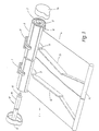
- an articulated arm awning 1 is illustrated with a tubular winding shaft 3 rotatably mounted in an awning box 2, on which an awning fabric 4 attached to it is partially wound into a bale 5.
- the awning box 2 consists of a tubular piece cut to length from an endless extruded profile, for example an extruded aluminum profile, which has a slot 6 which extends over the entire length and serves as an outlet slot for the awning fabric 4.
- the awning box 2 is seated in wall brackets 7 and 8 anchored to a wall of a building (not further illustrated), which surround the awning box 2 in a C-shaped and form-fitting manner and at the same time carry the wall-side joints 9 and 11 of articulated arms 12 and 13.
- a drop rod 14 with a circular cylindrical cross section is articulated in a known manner, to which the awning fabric 4 is attached.
- the end of the awning box 2 is closed by two caps 15 and 16, of which the cap 16 carries in a known manner a bearing device for the tubular fabric shaft 3, which is not visible in detail because of the representation of FIG. 1.
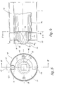
- the cap 15, on the other hand, carries the abbreviated drive motor 17, which is in the assembled state in the winding shaft 3, for which purpose its cylindrical housing 18 is designed to be correspondingly slim. From the inside end face of the housing 18 of the drive motor 17 an output shaft 19 provided with an external square looks out, which is to be described in detail below Coupling element 21 is coupled to the winding shaft 3.
- the housing 18 of the drive motor 17 contains, at its end illustrated in FIG. 2 on the left in a known manner, a transmission, the output shaft of which is the output shaft 19.
- the actual electric motor is located in the central region of the housing 18, while a limit switch device 20 is provided in the housing section shown broken open on the right.
- the limit switch device 20 contains a threaded spindle 22, which is mounted in the housing 18 and extends longitudinally, onto which an actuating piece 23 is screwed, which in a longitudinal guide (not shown in detail in FIG. 2) is held parallel to the threaded spindle 22 in a longitudinally displaceable and non-rotatable manner.
- a spur gear 24 is connected in a rotationally fixed manner, which protrudes from a corresponding opening provided on the circumferential side of the housing 18 with a part of its circumferential surface and engages there with an internal gear 25.
- the internal gear 25 is inserted in a tubular coupling piece 26, which is rotatably supported at its end 27 in the area of the end of the winding shaft 3 via a plastic bushing 28 on the cylindrical outer surface of the housing 18.
- the tubular coupling piece 26 extends coaxially between the winding shaft 3 and the housing 18 of the drive motor 17, namely that it extends, as shown in FIG. 2, to the inner end face of the housing 18 of the drive motor 17, where it is closed by a plate 29 , which is integrally connected to the tubular coupling piece 26.
- the end plate 29 contains a square-shaped opening 31, which is arranged coaxially to the tubular coupling piece 26 or the axis of the winding shaft 3 and through which the output shaft 19 passes in a form-fitting manner.
- the winding shaft 3 is in turn rotatably supported on the tubular coupling piece 26 by means of an inserted plastic bushing 32, so that a relative rotary movement is possible between the tubular coupling piece 26 and the winding shaft 3.
- two adjustable single-pole switch contacts 33 and 34 are to be actuated, via which the current can be supplied to the drive motor 17 in a known manner, namely the one switch 33 in the circuit through which the drive motor 17 is located
- the switch set 34 is arranged in a circuit via which the drive motor 17 can be switched on in the sense of unwinding or extending the awning fabric 4.
- the wiring required for this as well as the external switches to be operated by the operator for controlling the awning movement are known and are therefore not further illustrated in detail.
- the limit switches are actuated in this way depending on the number of revolutions of the output shaft 19.
- the output shaft 19 of the drive motor 17 begins to rotate in the sense of winding up the awning fabric 4, the torque generated by the output shaft 19 via the elastic coupling element 21 in the rotatably mounted winding shaft 3 is introduced, which then pulls the awning fabric 4 through the outlet slot 6, against the force exerted by the articulated arms 12 and 13 on the extension rod 14 on the awning fabric 4 in the sense of being pulled out of the outlet slot 6.
- the coupling tube 26, which is positively connected to the output shaft 19 is simultaneously set in corresponding rotations, and thus also the internal gear 25, which is connected in a rotationally fixed manner to the coupling tube 26.
- the internal gear 25 in turn drives the spur gear 24, which is in engagement therewith, so that the threaded spindle 22 rotates with the corresponding transmission ratio with the coupling tube 26.
- the actuating piece 23 secured against rotation gradually screws to the left, i.e. H. in the direction of the switch 33, which is adjusted so that it is opened after about an additional quarter turn of the winding shaft 3, after the drop rod 14 has applied the entire length to the mouth of the outlet slot 6, and thus the motor current in the sense of a further winding of the awning fabric 4 interrupts.
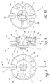
- the elastic coupling element 21 contains a circular cylindrical hub 35 with a coaxial square opening 36, by means of which the hub 35 can be placed on the output shaft 19 of the drive motor 17.
- Two circular disks 37 and 38 sit rotatably on the hub 35, but are secured in the axial direction, and have a corresponding concentric opening for this purpose, with which they are pushed onto the hub 35.
- the two disks 37 and 38 run parallel and at a distance from one another and are rigidly connected to one another by two rivets 39 and 41 which are diametrically opposite with respect to the square opening 36.
- Both disks 37 and 38 form the output side of the flexible coupling element 21 and are designed as drivers, for which purpose each of the two disks 37 and 38 contains a recess 42 which is open on the edge and which, in alignment with one another, engages around a bead 43 projecting inwards from the winding shaft 3, as can be seen in FIGS. 3 and 5.
- a leaf spring 44 wound in the manner of a clockwork spring, which is anchored with its inner end 45 in a rotationally fixed manner to the hub 35 and with its outer end 46 to the rivet 41.
- the flexible coupling element 21 also has a positive stop device 48.
- the form-fitting stop device contains a sector disk 51, which is fixed in a rotationally fixed manner, for example by means of welding spots, to the end face of the hub 35 facing the drive motor 17.
- the sector disk 51 has the shape shown in FIGS.
- the central angle is preferably at least greater than 90 °.
- the axial securing of the two driving disks 37 and 38 on the hub 35 takes place at one end by means of the sector disk 51 attached to the hub 35 and at the other end by means of a snap ring 55 inserted into a corresponding groove of the hub 35, while the hub 35 on the output shaft 19 by means of a spring sleeve 56 is axially secured, which is seated in a corresponding transverse bore at the free end of the output shaft 19, so that the hub 35 is fixed between the spring sleeve 56 and the end plate 29 of the tubular coupling piece 26.
- the flexible coupling element 21 with its hub 35 is pushed onto the square-shaped output shaft 19 and secured by means of the spring sleeve 56. Then, the two interconnected disks 37 and 38 of the flexible coupling element 21 are rotated in the shown winding direction of the leaf spring 44 against the direction of the arrow 47 so as to bias the spring 44 while the hub 35 is held. As soon as a sufficient pre-tensioning of the spring 44 is achieved, the drive motor 17 is pushed into the winding shaft 3 with the flexible coupling element 21 in front, the recesses 42 of the two disks 37 and 38 engaging around the inwardly projecting bead 43 of the winding shaft 3.
- the bead 43 can, as shown in the figures, be hollow and serve to fasten the inner edge of the awning fabric 4.
- the stop surface 53 of the sector disk 51 which is connected to the hub 35 in a rotationally fixed manner, is pulled against the bead 43 due to the pretensioning force of the spring 44.
- This pretensioning force is dimensioned such that the position shown in FIGS. 3 and 5 is maintained, even if the awning fabric 4 is pulled out of the outlet slot 6 by the force of the articulated arms 12 and 13 and the gravity of the extension rod 14, as a result of which - 5 - the winding shaft 3 against the biasing force of the spring 44, d. H. against the direction of arrow 47, would be rotated.
- the biasing force of the spring 44 prevents the winding shaft 3 from rotating relative to the sector disk 51 rigidly coupled to the output shaft 19 and from being released from the stop surface 53.
- the output shaft 19 begins in the direction of the arrow 47, i.e. counterclockwise to rotate, whereby the awning cloth attached to the winding shaft 3 with the inner edge is wound up into the ball 5.
- the relative position shown in FIGS. 3 and 5 between the sector disk 51 and the winding shaft 3 is maintained until the drop rod 14 comes into positive contact with the mouth of the outlet slot 6.
- the winding shaft 3 is positively held by means of the awning fabric 4 so that it can no longer rotate while the output shaft 19 of the drive motor 17 is still running, since the corresponding switch 33 has not yet interrupted the motor current.
- the sector disk 51 rotates further relative to the winding shaft 3 in the direction of the arrow 47, as a result of which the stop edge 53 is released from the bead 43 of the winding shaft 3.
- the switch 33 of the limit switch device 20 is expediently adjusted such that the switch 33 is opened by the actuating piece 23, if after the drop bar 14 has been placed against the mouth of the outlet slot 6, the sector disk 51 has made a quarter turn with respect to the winding shaft 3.
- the motor current is interrupted via the switch 33 and the output shaft 19 is stopped immediately. Since the transmission of the drive motor 17 is self-locking in a known manner, the drop rod 14 is always held under tension on the mouth of the outlet slot 6, the flow of force via the awning fabric 4, the winding shaft 3, the bead 43, the disks positively coupled to the bead 43 37 and 38, the leaf spring 41 to the hub 35 and from there to the locked output shaft 19. A renewed starting of the drive motor 17 for further winding of the awning fabric 4 is no longer possible because of the open switch 33 Lich. The drive motor 17 is only to be switched on in the opposite direction, ie in the sense of unwinding the awning cover, because the switch 34 is closed.
- the actuating piece 23 screws along the rotating screw spindle 22 from the switch 33 in the direction of the switch 34, which it opens - if the circuit is switched on by the operator - when the awning 1 is fully extended, for which the switch 34 is adjusted accordingly.
- the switch 34 is adjusted accordingly.
- the flexible coupling element 21 can compensate for the length when winding the awning fabric 4 onto the winding shaft 3. If it is assumed that the awning fabric 4 has lengthened by less than a quarter of the circumference in the course of time, then there is a correspondingly lower relative rotation between the output shaft 19, i. H. the hub 35 of the flexible coupling element 21 and the winding shaft 3, d. H. the sector disk 51 moves less from the basic position illustrated in FIG. 5, in which the stop surface 53 abuts the bead 43.
- the drop rod 14 comes to rest against the mouth of the outlet slot 6 with a smaller number of revolutions of the winding shaft 3, i.e. the winding shaft 3 comes to a standstill which lies before the point reached in the normal state, with length compensation up to a quarter winding circumference again being possible in the exemplary embodiment described.
- the unwinding takes place by means of a positive coupling from the output shaft 19 via the sector disk 51 to the bead 43 of the winding shaft 3, while during winding there is a non-positive connection from the winding shaft via the spring 44 to the output shaft 19, the spring 44 thus is strongly biased that between the sector disk 51 on the one hand and the two sides 37 and 38 or the winding shaft 3 no relative rotations occur until the drop bar 14 does not abut the mouth of the outlet slot 6.
- a further embodiment of a flexible coupling element 21 is illustrated, which differs from the previous embodiment essentially in that a cylindrical coil spring 61 is used as the elastic spring member instead of the leaf spring 44. Otherwise, the same reference numerals designate the same components as in the previous exemplary embodiment and are therefore not described again.
- the hub 35 is again provided, on which the sector disk 51 forming the stop device 48 is integrally formed on one end.
- the shape of the sector disk 51 corresponds to the shape as described for FIGS. 3, 4 and 5.
- a circular driving disk 37 is rotatably mounted, which, as before, engages around the bead 43 of the winding shaft 3 with its recess 42, which is open at the edge.
- the coil spring 61 is provided between the sector disk 51 and the drive plate 37, which coaxially surrounds the hub 35 or the square-shaped output shaft 19 with a corresponding radial clearance. Both ends 62 and 63 of the helical spring 61 are angled axially parallel to the output shaft 19 and are inserted in corresponding axially parallel bores 64 and 65 of the sector disk 51 and the driving disk 37.
- the drive plate 37 is secured in the axial direction in the direction of the sector plate 51 by the helical spring 61 and in the opposite direction by the snap ring 55 inserted in a corresponding groove of the hub 35, which, relative to the drive plate 37, lies opposite the helical spring 61 .
- the assembly is again carried out as before with a correspondingly preloaded helical spring 61, so that the rest position shown in FIG. 1 results, in which the stop surface 53 abuts the bead 43.
- the power transmission from the output shaft 19 follows the hub 35 from there to the integrally connected sector disk 51, from where the power is transmitted to the drive disk 37 via the helical spring 61.
- the driving plate 37 in turn drives the winding shaft 3.
- the winding shaft 3 stops and the continuing output shaft 19 pulls the coil spring 61 in the direction of arrow 47 until the switch 33 interrupts the current flow to the drive motor 17.
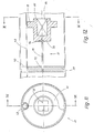
- a tension spring 71 is used, which winds with its longitudinal axis in the circumferential direction around the output shaft 19 and does not, like the helical spring 61, run coaxially with the output shaft 19.
- the sector disk 51 which in turn has the recess 52 open at the edge, is integrally formed on the hub 35. With the corresponding square opening 36, the hub 35 is positively coupled to the square output shaft 19, while the circular driving disk 37 lies flat on the sector disk 51, as can best be seen from FIG. 9. So that the drive plate 37 cannot migrate radially with respect to the sector disk 51, both the sector disk 51 and the drive plate 37 contain, on their mutually facing end faces, bores 72 and 73, in which an annular sleeve 74 is inserted, which places the two plates radially against one another specifies.
- the two disks 37 and 51 are held together by a disk 74 seated on the output shaft 19, which is axially secured by a dowel pin or spring sleeve 56 seated in a corresponding transverse bore in the output shaft 19, while another dowel pin 75 inserted in the output shaft 19 on the outer end face of the sector disk 51 prevents axial migration in the opposite direction.
- the two opposing plane surfaces of the driving plate 37 and the sector plate 51 each contain a further recess 76 and 77, which is radially more external to the recesses 72 and 73. Both recesses 76 and 77 align with one another and form an approximately square-shaped cavity which is circular and concentrically surrounds the output shaft 19.
- the tension spring 71 is arranged, which carries eyelets 79 and 81 on both ends and is thus suspended in corresponding pins 82 and 83.
- the two pins 82 and 83 are located in the cavity 78, namely the pin 82 is axially parallel to the drive plate 37 and the pin 83 is axially parallel to the sector disk 51 in each case in the cavity 78.
- the tension spring 71 extending between the two pins 82 and 83 is, when the flexible coupling element 21 is mounted together with the drive motor 17 in the winding shaft, biased again and attempts to turn the sector disk 51 with respect to the driving disk 37 against the direction of arrow 47 .
- the bead 43 of the winding shaft 3 is clamped between the recess 42 of the drive plate 37 and the stop edge 53 of the sector disk 61, which leads to the fact that when the drive motor 17 is started up in the sense of a winding up of the awning cloth 4, that emitted by the drive motor 17 Torque is transmitted from the output shaft 19 to the hub 35, which is in turn rotatably coupled therewith, and the sector disk 51 connected in one piece to the hub 35 to the tension spring 71. From the tension spring 71, the force is transmitted to the pin 82 and thus to the drive plate 37, which in turn drives the winding shaft.
- a length compensation of the awning fabric 4 is possible via the flexible coupling element 21, and the switch 33 can be adjusted to a middle position, which ensures that the extension rod 14 lies sealingly against the mouth of the outlet slot 6 under all operating conditions.
- the torque for unwinding the awning fabric 4 from the winding shaft 3 is transmitted to the winding shaft via the stop edge 53 of the sector disk 51.
- the exemplary embodiment of the flexible coupling element 21 illustrated in FIGS. 11 and 12 contains, as an elastic coupling member, a torsion bar 91 formed from a flat bar.
- the flat bar 91 is positively inserted at one end in a correspondingly designed opening 92 in the driving disk 37 and is also form-fitting with the hub 35 at the other end connected.
- the hub 35 contains the square opening 36, which is now in the form of a blind hole, for receiving the output shaft 19.
- the end of the torsion bar 91 facing away from the driving disk 37 is inserted in the end wall 93 of the hub 35 thus obtained, in a corresponding opening 94.
- the driving plate 37 was located in the immediate vicinity of the hub 35 or was rotatably mounted thereon, in the exemplary embodiment according to FIGS. 11 and 12 the hub 35 and the driving plate 37 are axially spaced from one another , ie by the length of the torsion bar 91, apart from each other, both with the Drive plate 37 and fixedly connected to the hub 35; the drive plate 37 fits into the winding shaft 3 with little play.
- the elastic coupling element 21 according to FIGS. 11 and 12 is fastened with the hub 35 to the square-shaped output shaft 19 of the drive motor 17 by suitable means, not shown in more detail, and the arrangement of elastic coupling element 21 and drive motor 17 thus obtained is included of the tubular coupling piece 26 inserted into the winding shaft 3, the edge-side recess 42 of the driving plate 37 engaging around the bead 43.
- the use of the torsion bar 91 has the advantage over the previous exemplary embodiments that the arrangement can be mounted stress-free because torques 91 which run coaxially to the winding shaft 3 or the output shaft 19 can transmit torques in both directions of rotation, i. H. Both the torque for winding and the dimming torque for unwinding can be introduced into the winding shaft 3 via the torsion bar 91.
- the sector disk 51 described above is therefore unnecessary; moreover, the torsion bar 91 again allows a relative rotation between the drive shaft 19 and the winding shaft 3 in order to achieve a length compensation between the adjustment of the limit switch 33 and the actual winding length of the awning fabric 4.
- the number of revolutions of the output shaft of the drive motor is the criterion for actuating the two switches 33 and 34.
Landscapes
- Engineering & Computer Science (AREA)
- Architecture (AREA)
- Structural Engineering (AREA)
- Civil Engineering (AREA)
- Building Awnings And Sunshades (AREA)
- Tents Or Canopies (AREA)
- Operating, Guiding And Securing Of Roll- Type Closing Members (AREA)
Claims (17)
Priority Applications (1)
| Application Number | Priority Date | Filing Date | Title |
|---|---|---|---|
| AT84109163T ATE47452T1 (de) | 1983-09-23 | 1984-08-02 | Markise mit nachgiebiger motorkupplung. |
Applications Claiming Priority (2)
| Application Number | Priority Date | Filing Date | Title |
|---|---|---|---|
| DE19833334416 DE3334416A1 (de) | 1983-09-23 | 1983-09-23 | Markise mit nachgiebiger motorkupplung |
| DE3334416 | 1983-09-23 |
Publications (3)
| Publication Number | Publication Date |
|---|---|
| EP0135731A2 EP0135731A2 (fr) | 1985-04-03 |
| EP0135731A3 EP0135731A3 (en) | 1986-07-30 |
| EP0135731B1 true EP0135731B1 (fr) | 1989-10-18 |
Family
ID=6209846
Family Applications (1)
| Application Number | Title | Priority Date | Filing Date |
|---|---|---|---|
| EP84109163A Expired EP0135731B1 (fr) | 1983-09-23 | 1984-08-02 | Marquise avec moteur à accouplement flexible |
Country Status (4)
| Country | Link |
|---|---|
| US (1) | US4615371A (fr) |
| EP (1) | EP0135731B1 (fr) |
| AT (1) | ATE47452T1 (fr) |
| DE (2) | DE3334416A1 (fr) |
Families Citing this family (62)
| Publication number | Priority date | Publication date | Assignee | Title |
|---|---|---|---|---|
| EP0230476B1 (fr) * | 1985-10-25 | 1989-03-29 | Carlo Maurizio Pozzi | Dispositif de sécurité pour marquise pour véhicules, caravanes ou similaires |
| CA1260025A (fr) * | 1985-11-14 | 1989-09-26 | M & I Door Systems Limited | Mecanisme de manoeuvre (ouverture et fermeture) d'une porte de complexe industriel |
| DE3546093A1 (de) * | 1985-12-24 | 1987-07-02 | Hassinger Gmbh Co Kg | Antriebsvorrichtung fuer bewegliche stoffabdeckungen |
| WO1988009856A1 (fr) * | 1987-06-11 | 1988-12-15 | Belanga Pty. Ltd. | Auvent ameliore |
| US5056839A (en) * | 1988-05-30 | 1991-10-15 | Yoon Yi C | Automobile cover assembly |
| US4974658A (en) * | 1989-02-22 | 1990-12-04 | Komatsu Denki Sangyo Kabushiki Kaisha | Sheet shutter |
| FR2653160B1 (fr) * | 1989-10-18 | 1992-01-17 | Simu | Dispositif d'enroulement de fermeture du genre a mecanisme d'entrainement loge dans le tambour de manóoeuvre. |
| DE4140607C2 (de) * | 1991-12-10 | 1994-09-01 | Clauss Markisen | Reihenanlage aus Gegenzugmarkisen |
| DE4209972C2 (de) * | 1992-03-27 | 1994-05-19 | Mhz Sonnenschutztech Gmbh | Markise |
| US5307856A (en) * | 1992-11-27 | 1994-05-03 | Carefree/Scott Fetzer Company | Automatically retractable awning |
| US5407007A (en) * | 1993-05-27 | 1995-04-18 | Robert S. Lowery | Motorized canister awning |
| DE4318436A1 (de) * | 1993-06-03 | 1995-02-16 | Rau Metall Gmbh & Co | Markise mit einer Tragstange |
| DE4318437A1 (de) * | 1993-06-03 | 1994-12-08 | Rau Metall Gmbh & Co | Markise mit einem Tragprofil |
| DE4333996A1 (de) * | 1993-10-06 | 1995-04-13 | Geiger Gerhard Gmbh & Co | Einstellvorrichtung für Markisen und Rolläden |
| DE19519440A1 (de) * | 1995-05-26 | 1996-11-28 | Theodor Kuhlmann | Rolladen für Fenster und Fenstertüren |
| FR2741900B1 (fr) * | 1995-10-23 | 1998-05-07 | Franciaflex | Banne equipee d'un motoreducteur sans installation electrique externe a la banne |
| CH688006A5 (fr) * | 1995-10-30 | 1997-04-15 | Somfy | Dispositif de manoeuvre d'un élément de fermeture se déplacant au moins approximativement verticalement. |
| US6273172B1 (en) | 1998-08-20 | 2001-08-14 | White Consolidated Industries, Inc. | Motor operated awning |
| US6095221A (en) | 1998-08-20 | 2000-08-01 | White Consolidated Industries, Inc. | Awning extension and retraction mechanism |
| US6142209A (en) * | 1999-11-19 | 2000-11-07 | Girard Systems, Inc. | Closed box motorized window awning |
| DE10035796A1 (de) * | 2000-07-22 | 2002-01-31 | Schmitz Werke | Markise |
| CA2323843A1 (fr) | 2000-10-19 | 2002-04-19 | Emilio Petrongolo | Dispositif d'ouverture et de fermeture d'un velum |
| FR2830061B1 (fr) | 2001-09-21 | 2003-12-19 | Somfy | Dispositif d'accouplement elastique destine a aligner deux pieces en rotation |
| FR2841615B1 (fr) † | 2002-07-01 | 2004-08-20 | Thiriet Fils | Embout pour dispositif d'enroulement d'un element enroulable tel que bache ou similaire, notamment d'un vehicule |
| US6843301B2 (en) * | 2002-09-09 | 2005-01-18 | Dometic Corporation | Awning roller with internal motor |
| US6782936B1 (en) | 2003-02-14 | 2004-08-31 | Girard Systems, Inc. | Awning system for a recreational vehicle |
| US20060272782A1 (en) * | 2003-10-23 | 2006-12-07 | Lutron Electronics Co., Inc. | System for coupling roller shade tubes |
| US7051782B2 (en) * | 2003-10-23 | 2006-05-30 | Lutron Electronics Co., Inc. | System for coupling roller shade tubes |
| US7513289B2 (en) * | 2004-06-07 | 2009-04-07 | Girard Systems | Slide-lateral arm box awning for motor home and recreational vehicle use |
| US7261115B2 (en) * | 2004-06-07 | 2007-08-28 | Girard Systems | Combo slide-window awning |
| BE1016242A3 (fr) * | 2004-10-15 | 2006-06-06 | Dynaco International Sa | Dispositif avec un tambour dans lequel est monte un moteur d'entrainement. |
| US7163257B2 (en) * | 2004-10-26 | 2007-01-16 | Girard Systems | Slide out awning mechanism |
| DE202005001875U1 (de) * | 2005-02-05 | 2005-05-19 | Rewalux Markisenvertrieb Gmbh | Verstellbares Sonnensegel mit einer Plane |
| JP4817146B2 (ja) * | 2005-03-10 | 2011-11-16 | 収 伊藤 | 複合オーニング装置 |
| ITTV20050024U1 (it) * | 2005-05-06 | 2006-11-07 | Nice Spa | Dispositivo di fine-corsa per azionamenti di avvolgibili o protezioni solari. |
| DE102006026533A1 (de) * | 2006-05-17 | 2007-11-22 | Agrotel Gmbh | Rolltor |
| US7628194B2 (en) * | 2006-08-07 | 2009-12-08 | Carefree/Scott Fetzer Company | Dual angled canopy retractable awning |
| DE102007012259A1 (de) * | 2007-03-12 | 2008-09-18 | Bos Gmbh & Co. Kg | Sonnenschutzrollo für Kraftfahrzeuge |
| ITMI20070492A1 (it) * | 2007-03-13 | 2008-09-14 | Faac Spa | Gruppo motore elettrico tubolare adattabile per elementi avvolgibili quali tapparelle e simili |
| CN101059707B (zh) * | 2007-04-18 | 2010-12-15 | 张家港市红叶视听器材有限公司 | 电动卷绕限位检测装置 |
| US8887542B2 (en) * | 2007-10-31 | 2014-11-18 | Schlage Lock Company | Motor drive mechanism for an electronic deadbolt lock |
| US20090256021A1 (en) * | 2008-04-15 | 2009-10-15 | David M. Dorrough | Assembly to wind cords in a motorized window covering |
| US8307878B2 (en) | 2009-01-14 | 2012-11-13 | Hunter Douglas Inc. | Noise dampening motor drive system for retractable covering for architectural openings |
| FR2945091B1 (fr) * | 2009-04-30 | 2011-05-13 | Somfy Sas | Dispositif de transmission viscoelastique d'un actionneur d'un volet roulant |
| ITUD20090094A1 (it) * | 2009-05-14 | 2010-11-15 | Pratic F Lli Orioli S P A | Meccanismo di ammortizzazione per un elemento di copertura avvolgibile ed elemento di copertura avvolgibile comprendente tale meccanismo |
| US20100307701A1 (en) * | 2009-06-09 | 2010-12-09 | Thomas Peterson | Integrated quiet Motorized Roller Shade System |
| US8887785B2 (en) * | 2009-08-11 | 2014-11-18 | Carefree/Scott Fetzer Co. | Awning control with multidimensional motion sensing |
| DE102012202824B3 (de) * | 2012-02-24 | 2013-07-11 | Schmitz-Werke Gmbh + Co. Kg | Markise mit schwingungsgedämpftem Antrieb |
| FR2992142B1 (fr) * | 2012-06-13 | 2014-07-11 | Somfy Sas | Element de support d’une batterie dans un tube d’enroulement d’un ecran domotique. |
| FR2992114B1 (fr) | 2012-06-13 | 2016-08-19 | Somfy Sas | Dispositif motorise de manoeuvre destine a la manoeuvre d’un ecran mobile a toile enroulable d’un dispositif de couverture de fenetre ou d’ecran de projection. |
| US10934773B2 (en) | 2012-06-13 | 2021-03-02 | Somfy Activites Sa | Motorized manoeuvring device intended to manoeuvre a moving windable fabric screen of a window or projection screen cover device |
| FR3008255B1 (fr) * | 2013-07-03 | 2015-07-31 | Somfy Sas | Actionneur d'entrainement d'un ecran domotique et installation comprenant un tel actionneur |
| DE202014001436U1 (de) * | 2013-10-22 | 2015-01-23 | GfA ELEKTROMATEN GmbH & Co. KG | Sicherungsvorrichtung für einen kraftgetriebenen Gebäudeabschluss, Sektionaltor |
| US9695635B2 (en) | 2014-05-15 | 2017-07-04 | Dometic Corporation | Power track awning assembly |
| US9228359B2 (en) * | 2014-05-15 | 2016-01-05 | Dometic Corporation | Rotatable awning with illumination |
| JP6426464B2 (ja) * | 2014-12-25 | 2018-11-21 | 立川ブラインド工業株式会社 | 電動日射遮蔽装置及び電動日射遮蔽装置の制御方法 |
| USD805019S1 (en) | 2015-05-15 | 2017-12-12 | Dometic Sweden Ab | Accessory base |
| USD805458S1 (en) | 2015-05-15 | 2017-12-19 | Dometic Sweden Ab | Accessory base |
| US10938337B1 (en) | 2015-09-26 | 2021-03-02 | Thomas E. Carleton | System for guidance and deployment of active panels on building walls |
| CN105507515B (zh) * | 2016-01-25 | 2018-11-30 | 罗诚 | 建筑外墙可控遮阳装置 |
| CN106150000B (zh) * | 2016-08-03 | 2019-07-02 | 邯郸市肥乡区农乐机械科技有限公司 | 一种建筑物前的伸缩式遮阳罩 |
| TW202232011A (zh) | 2017-02-06 | 2022-08-16 | 美商漢特道格拉斯股份有限公司 | 用於減小馬達總成中之雜訊之方法及設備 |
Family Cites Families (14)
| Publication number | Priority date | Publication date | Assignee | Title |
|---|---|---|---|---|
| US2254566A (en) * | 1938-08-27 | 1941-09-02 | Jr Edward S Cornell | Flexible coupling |
| US2962647A (en) * | 1956-04-16 | 1960-11-29 | Arnold L Borenstein | Light sensitive motor control |
| US3285325A (en) * | 1964-03-19 | 1966-11-15 | Ametek Inc | Actuator for retractable wall |
| US3285089A (en) * | 1964-04-13 | 1966-11-15 | Nihon Bunka Roller Shutter Com | Drive mechanism for a shutter winding device |
| US3847171A (en) * | 1971-01-22 | 1974-11-12 | H Westfall | Motorized awning control apparatus |
| DE2512102C3 (de) * | 1975-03-19 | 1979-01-18 | Siemens Ag, 1000 Berlin Und 8000 Muenchen | Abschalteinheit in einer Elektromotor-Antriebseinheit für Markisen und Rolladen |
| DE2514941C3 (de) * | 1975-04-05 | 1984-06-20 | Clauss Markisen, 7311 Bissingen | Markise |
| FR2311170A1 (fr) * | 1975-05-13 | 1976-12-10 | Lauzier Rene | Dispositif d'enroulement pour stores a rouleau et similaires |
| DE7809535U1 (de) * | 1978-03-31 | 1978-09-21 | Emil Und Adolf Becker Kg, 6349 Sinn | Antriebswelle fuer einen rolladen, eine markise o.dgl. |
| DE2830360A1 (de) * | 1978-07-11 | 1980-01-24 | Gross Hans | Antriebsvorrichtung fuer rolladen, jalousien, markisen o.dgl. |
| FR2455695A1 (fr) * | 1979-05-02 | 1980-11-28 | Carpano & Pons | Dispositif de commande pour moto-reducteur electrique |
| US4372367A (en) * | 1979-06-12 | 1983-02-08 | Baldanello U | Roller blinds |
| NZ194124A (en) * | 1979-07-04 | 1984-05-31 | Firmaframe Nominees Pty Ltd | Mechanism for stopping and reversing roller door drives |
| FR2480846A1 (fr) * | 1980-04-18 | 1981-10-23 | Carpano & Pons | Dispositif d'entrainement, pour stores a rouleau, volets roulants, ou similaires |
-
1983
- 1983-09-23 DE DE19833334416 patent/DE3334416A1/de not_active Ceased
-
1984
- 1984-08-02 EP EP84109163A patent/EP0135731B1/fr not_active Expired
- 1984-08-02 DE DE8484109163T patent/DE3480223D1/de not_active Expired
- 1984-08-02 AT AT84109163T patent/ATE47452T1/de not_active IP Right Cessation
- 1984-09-17 US US06/651,303 patent/US4615371A/en not_active Expired - Fee Related
Also Published As
| Publication number | Publication date |
|---|---|
| DE3334416A1 (de) | 1985-04-11 |
| US4615371A (en) | 1986-10-07 |
| EP0135731A3 (en) | 1986-07-30 |
| ATE47452T1 (de) | 1989-11-15 |
| EP0135731A2 (fr) | 1985-04-03 |
| DE3480223D1 (en) | 1989-11-23 |
Similar Documents
| Publication | Publication Date | Title |
|---|---|---|
| EP0135731B1 (fr) | Marquise avec moteur à accouplement flexible | |
| DE3110079C2 (fr) | ||
| EP0748719A2 (fr) | Miroir extérieur d'un véhicule avec tête à miroir pivotable à moteur | |
| EP1205361A2 (fr) | Dispositif de séparation pour un véhicule automobile | |
| DE3504489A1 (de) | Vorrichtung zur handbetaetigung der elektromotorisch antreibbaren wickelwelle z.b. eines rolladens bei stromlosem elektromotor | |
| DE3420789C2 (fr) | ||
| EP0598334B1 (fr) | Dispositif de vissage | |
| DE19706209A1 (de) | Vorrichtung zur Steuerung, insbesondere Endabschaltung einer motorischen Antriebsvorrichtung einer Wickelwelle eines Rolladens, Garagentors o. dgl. | |
| DE4237385A1 (de) | Antrieb für einen Flügel, insbesondere Kipp- oder Klappflügel | |
| EP0150061B1 (fr) | Moulinet de pêche | |
| EP0622260A1 (fr) | Dispositif d'actionnement de parties mobiles pour véhicule | |
| DE3226400A1 (de) | Fensterrollo, insbesondere fuer kraftfahrzeuge | |
| DE3718513C2 (de) | Wendevorrichtung für eine raffbare Lamellenjalousie | |
| DE3503816C2 (fr) | ||
| DE2830360A1 (de) | Antriebsvorrichtung fuer rolladen, jalousien, markisen o.dgl. | |
| DE4108955A1 (de) | Verstelleinrichtung, insbesondere zum einstellen von fahrzeugsitzen | |
| DE3240495A1 (de) | Rohrmotor-endschalter | |
| DE2739151C2 (de) | Endschaltervorrichtung, insbesondere für Rolladen und Jalousien | |
| EP1279789A1 (fr) | Dispositif separateur pour une unité d'entraînement | |
| EP1102908B1 (fr) | Arret de porte | |
| DE102005008486B4 (de) | Insektenschutzrollo | |
| DE3400778C2 (fr) | ||
| DE19617740C1 (de) | Vorrichtung zur Antriebsabschaltung des Motors elektrisch betriebener Markisen, Markisoletten u. dgl. | |
| AT412984B (de) | Elektrischer antrieb für rolladen oder dergleichen | |
| DE1275910B (de) | Getriebe eines Treibstangenbeschlages fuer Fenster, Tueren od. dgl., insbesondere fuer Kipp-Schwenkfluegel-Fenster |
Legal Events
| Date | Code | Title | Description |
|---|---|---|---|
| PUAI | Public reference made under article 153(3) epc to a published international application that has entered the european phase |
Free format text: ORIGINAL CODE: 0009012 |
|
| AK | Designated contracting states |
Designated state(s): AT BE CH DE FR GB IT LI LU NL SE |
|
| PUAL | Search report despatched |
Free format text: ORIGINAL CODE: 0009013 |
|
| AK | Designated contracting states |
Kind code of ref document: A3 Designated state(s): AT BE CH DE FR GB IT LI LU NL SE |
|
| 17P | Request for examination filed |
Effective date: 19861014 |
|
| RBV | Designated contracting states (corrected) |
Designated state(s): AT BE CH DE FR GB IT LI NL SE |
|
| 17Q | First examination report despatched |
Effective date: 19880202 |
|
| GRAA | (expected) grant |
Free format text: ORIGINAL CODE: 0009210 |
|
| AK | Designated contracting states |
Kind code of ref document: B1 Designated state(s): AT BE CH DE FR GB IT LI NL SE |
|
| REF | Corresponds to: |
Ref document number: 47452 Country of ref document: AT Date of ref document: 19891115 Kind code of ref document: T |
|
| ITF | It: translation for a ep patent filed |
Owner name: JACOBACCI & PERANI S.P.A. |
|
| REF | Corresponds to: |
Ref document number: 3480223 Country of ref document: DE Date of ref document: 19891123 |
|
| GBT | Gb: translation of ep patent filed (gb section 77(6)(a)/1977) | ||
| ET | Fr: translation filed | ||
| PLBE | No opposition filed within time limit |
Free format text: ORIGINAL CODE: 0009261 |
|
| STAA | Information on the status of an ep patent application or granted ep patent |
Free format text: STATUS: NO OPPOSITION FILED WITHIN TIME LIMIT |
|
| 26N | No opposition filed | ||
| ITTA | It: last paid annual fee | ||
| EAL | Se: european patent in force in sweden |
Ref document number: 84109163.0 |
|
| PGFP | Annual fee paid to national office [announced via postgrant information from national office to epo] |
Ref country code: GB Payment date: 19960710 Year of fee payment: 13 |
|
| PGFP | Annual fee paid to national office [announced via postgrant information from national office to epo] |
Ref country code: SE Payment date: 19960819 Year of fee payment: 13 |
|
| PGFP | Annual fee paid to national office [announced via postgrant information from national office to epo] |
Ref country code: NL Payment date: 19960831 Year of fee payment: 13 |
|
| PGFP | Annual fee paid to national office [announced via postgrant information from national office to epo] |
Ref country code: BE Payment date: 19960913 Year of fee payment: 13 |
|
| PG25 | Lapsed in a contracting state [announced via postgrant information from national office to epo] |
Ref country code: GB Free format text: LAPSE BECAUSE OF NON-PAYMENT OF DUE FEES Effective date: 19970802 |
|
| PG25 | Lapsed in a contracting state [announced via postgrant information from national office to epo] |
Ref country code: SE Free format text: LAPSE BECAUSE OF NON-PAYMENT OF DUE FEES Effective date: 19970803 |
|
| PG25 | Lapsed in a contracting state [announced via postgrant information from national office to epo] |
Ref country code: BE Free format text: LAPSE BECAUSE OF NON-PAYMENT OF DUE FEES Effective date: 19970831 |
|
| BERE | Be: lapsed |
Owner name: CLAUSS MARKISEN Effective date: 19970831 |
|
| PG25 | Lapsed in a contracting state [announced via postgrant information from national office to epo] |
Ref country code: NL Free format text: LAPSE BECAUSE OF NON-PAYMENT OF DUE FEES Effective date: 19980301 |
|
| GBPC | Gb: european patent ceased through non-payment of renewal fee |
Effective date: 19970802 |
|
| EUG | Se: european patent has lapsed |
Ref document number: 84109163.0 |
|
| NLV4 | Nl: lapsed or anulled due to non-payment of the annual fee |
Effective date: 19980301 |
|
| PGFP | Annual fee paid to national office [announced via postgrant information from national office to epo] |
Ref country code: AT Payment date: 19980730 Year of fee payment: 15 |
|
| PGFP | Annual fee paid to national office [announced via postgrant information from national office to epo] |
Ref country code: CH Payment date: 19980805 Year of fee payment: 15 |
|
| PGFP | Annual fee paid to national office [announced via postgrant information from national office to epo] |
Ref country code: FR Payment date: 19980813 Year of fee payment: 15 |
|
| PG25 | Lapsed in a contracting state [announced via postgrant information from national office to epo] |
Ref country code: AT Free format text: LAPSE BECAUSE OF NON-PAYMENT OF DUE FEES Effective date: 19990802 |
|
| PG25 | Lapsed in a contracting state [announced via postgrant information from national office to epo] |
Ref country code: LI Free format text: LAPSE BECAUSE OF NON-PAYMENT OF DUE FEES Effective date: 19990831 Ref country code: CH Free format text: LAPSE BECAUSE OF NON-PAYMENT OF DUE FEES Effective date: 19990831 |
|
| PGFP | Annual fee paid to national office [announced via postgrant information from national office to epo] |
Ref country code: DE Payment date: 19991020 Year of fee payment: 16 |
|
| REG | Reference to a national code |
Ref country code: CH Ref legal event code: PL |
|
| PG25 | Lapsed in a contracting state [announced via postgrant information from national office to epo] |
Ref country code: FR Free format text: LAPSE BECAUSE OF NON-PAYMENT OF DUE FEES Effective date: 20000428 |
|
| REG | Reference to a national code |
Ref country code: FR Ref legal event code: ST |
|
| PG25 | Lapsed in a contracting state [announced via postgrant information from national office to epo] |
Ref country code: DE Free format text: LAPSE BECAUSE OF NON-PAYMENT OF DUE FEES Effective date: 20010501 |