EP0135702A1 - Riemenübertragung für einen angetriebenen Rasenmäher - Google Patents
Riemenübertragung für einen angetriebenen Rasenmäher Download PDFInfo
- Publication number
- EP0135702A1 EP0135702A1 EP84108746A EP84108746A EP0135702A1 EP 0135702 A1 EP0135702 A1 EP 0135702A1 EP 84108746 A EP84108746 A EP 84108746A EP 84108746 A EP84108746 A EP 84108746A EP 0135702 A1 EP0135702 A1 EP 0135702A1
- Authority
- EP
- European Patent Office
- Prior art keywords
- belt
- pulley
- transmission
- drive
- tensioning assembly
- Prior art date
- Legal status (The legal status is an assumption and is not a legal conclusion. Google has not performed a legal analysis and makes no representation as to the accuracy of the status listed.)
- Granted
Links
Images


Classifications
-
- A—HUMAN NECESSITIES
- A01—AGRICULTURE; FORESTRY; ANIMAL HUSBANDRY; HUNTING; TRAPPING; FISHING
- A01D—HARVESTING; MOWING
- A01D34/00—Mowers; Mowing apparatus of harvesters
- A01D34/01—Mowers; Mowing apparatus of harvesters characterised by features relating to the type of cutting apparatus
- A01D34/412—Mowers; Mowing apparatus of harvesters characterised by features relating to the type of cutting apparatus having rotating cutters
- A01D34/63—Mowers; Mowing apparatus of harvesters characterised by features relating to the type of cutting apparatus having rotating cutters having cutters rotating about a vertical axis
- A01D34/67—Mowers; Mowing apparatus of harvesters characterised by features relating to the type of cutting apparatus having rotating cutters having cutters rotating about a vertical axis hand-guided by a walking operator
- A01D34/68—Mowers; Mowing apparatus of harvesters characterised by features relating to the type of cutting apparatus having rotating cutters having cutters rotating about a vertical axis hand-guided by a walking operator with motor driven cutters or wheels
- A01D34/6806—Driving mechanisms
-
- A—HUMAN NECESSITIES
- A01—AGRICULTURE; FORESTRY; ANIMAL HUSBANDRY; HUNTING; TRAPPING; FISHING
- A01D—HARVESTING; MOWING
- A01D34/00—Mowers; Mowing apparatus of harvesters
- A01D34/01—Mowers; Mowing apparatus of harvesters characterised by features relating to the type of cutting apparatus
- A01D34/412—Mowers; Mowing apparatus of harvesters characterised by features relating to the type of cutting apparatus having rotating cutters
- A01D34/63—Mowers; Mowing apparatus of harvesters characterised by features relating to the type of cutting apparatus having rotating cutters having cutters rotating about a vertical axis
- A01D34/67—Mowers; Mowing apparatus of harvesters characterised by features relating to the type of cutting apparatus having rotating cutters having cutters rotating about a vertical axis hand-guided by a walking operator
- A01D34/68—Mowers; Mowing apparatus of harvesters characterised by features relating to the type of cutting apparatus having rotating cutters having cutters rotating about a vertical axis hand-guided by a walking operator with motor driven cutters or wheels
- A01D34/69—Mowers; Mowing apparatus of harvesters characterised by features relating to the type of cutting apparatus having rotating cutters having cutters rotating about a vertical axis hand-guided by a walking operator with motor driven cutters or wheels with motor driven wheels
-
- F—MECHANICAL ENGINEERING; LIGHTING; HEATING; WEAPONS; BLASTING
- F16—ENGINEERING ELEMENTS AND UNITS; GENERAL MEASURES FOR PRODUCING AND MAINTAINING EFFECTIVE FUNCTIONING OF MACHINES OR INSTALLATIONS; THERMAL INSULATION IN GENERAL
- F16H—GEARING
- F16H9/00—Gearings for conveying rotary motion with variable gear ratio, or for reversing rotary motion, by endless flexible members
- F16H9/02—Gearings for conveying rotary motion with variable gear ratio, or for reversing rotary motion, by endless flexible members without members having orbital motion
- F16H9/04—Gearings for conveying rotary motion with variable gear ratio, or for reversing rotary motion, by endless flexible members without members having orbital motion using belts, V-belts, or ropes
- F16H9/12—Gearings for conveying rotary motion with variable gear ratio, or for reversing rotary motion, by endless flexible members without members having orbital motion using belts, V-belts, or ropes engaging a pulley built-up out of relatively axially-adjustable parts in which the belt engages the opposite flanges of the pulley directly without interposed belt-supporting members
- F16H9/14—Gearings for conveying rotary motion with variable gear ratio, or for reversing rotary motion, by endless flexible members without members having orbital motion using belts, V-belts, or ropes engaging a pulley built-up out of relatively axially-adjustable parts in which the belt engages the opposite flanges of the pulley directly without interposed belt-supporting members using only one pulley built-up out of adjustable conical parts
-
- A—HUMAN NECESSITIES
- A01—AGRICULTURE; FORESTRY; ANIMAL HUSBANDRY; HUNTING; TRAPPING; FISHING
- A01D—HARVESTING; MOWING
- A01D2101/00—Lawn-mowers
Definitions
- the present invention relates to a power lawn-mower of the principal construction described in the Swedish patent specification SE - B-7313735-8.
- the previously known lawn-mower according to said patent specification comprises a belt transmission between the drive engine and the front wheel shaft, whereby the front wheels are driven.
- Such a belt transmission operates very well for this type of lawn-mower.
- the transmission is changed from driving operation to idling.
- the object of the present invention is to provide a transmission for a lawn-mower, which has more than one transmission ratio.
- Another object of the present invention is to provide a belt transmission which is adaptable to lawn-mowers of different sizes having different distances between the drive shaft of the engine and the shaft of the driven wheel.
- a belt transmission for a lawn-mower having a drive engine and a driven wheel positioned on a shaft.
- the transmission comprises a variator pulley, splined to the output shaft of the drive engine, a pulley adapted at the wheel, a drive belt trained therebetween and a belt tensioning assembly having three distinct positions.
- the belt tensioning assembly is biased by a shackle spring and is movable between a first disengaged position, in which the belt is free from cooperation with the pulleys, and a second drive position, in which the belt drivingly cooperates with the pulleys.
- a third position is reached, in which the belt cooperates with the smallest diameter of the variator pulley. In this way, a second drive speed is achieved.
- the transmission cap is divided into two pivotably interconnected portions.
- the portions form an angle in relation to each other.
- the pulleys are positioned at the end of the cap spaced from the joint position. By changing the angle between the cap portions, the distance between the pulleys can be allowed to vary.
- the transmission is adaptable to different distances between the engine shaft and the wheel shaft.
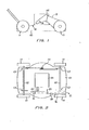
- Fig. 1 is a side view of a lawn-mower equipped with a belt transmission according to the invention.
- Fig. 2 is a plan view of the lawn-mower according to Fig. 1.
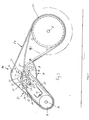
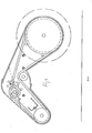
- Figs. 3, 4 and 5 are cross-sectional views through the belt transmission of Fig. 1 taken according to the line III-III of Fig. 2 and show the transmission in the disengaged position, normal high speed and low speed, respectively.
- Fig. 6 is a cross section taken according to the line VI-VI of Fig. 1 and in an enlarged scale.
- a lawn-mower comprising a rotor cap 10 enclosing a rotor having knives for cutting the grass, and an internal combustion engine 15, which drives the rotor.
- Four wheels 11 are adapted on two shafts 12, which are supported by levers 13.
- the levers 13 are pivotably journalled in the rotor cap 10 and are interconnected by a link system 14, so that the height of the wheel shafts and thus the mowing height is adjustable.
- the engine 15 is elastically supported on the rotor cap and is directly connected to the rotor.
- the engine has a second output shaft 19 for powering the lawn--mower as described more in details below.
- a belt transmission 18 is adapted between the output shaft 19 of the engine 15 and one of the front wheels 16.
- a protection sleeve 17 surrounds the output shaft 19.
- the belt transmission 18 is shown in cross-section in Figs. 3 to 5.
- the transmission is enclosed by a cap 20 divided into two portions, a first portion 21 positioned closest to the engine 15 and a second portion 22 positioned towards the driven wheel 16.
- the first and the second portion are pivotably interconnected by means of a pin 23, or similar.
- the second portion 22 is placed inside the first portion at the overlapping portion 24 as shown in Fig. 3.
- the cap portions 21 and 22 can thus be pivoted in relation to each other at least in a limited degree.
- a drive belt 25 is trained inside the transmission on a drive pulley 26 and a driven pulley 27.
- the driven pulley 27 is directly connected to the driven wheel or is integrally shaped with the wheel.
- the drive pulley 26 is connected to the output shaft 19 of the engine 15 as described in details below by reference to Fig. 6.
- a belt tensioning assembly generally designated 28.
- a belt tensioning roll 29 which simply can be a ball bearing, the outer member of which constitutes a rolling surface for the backside of the drive belt.
- the roller 29 is movable in a slit 30 and is locked in a suitable position for pretensioning the belt 25.
- the belt tensioning assembly 28 comprises a lever 32, which is pivotably journalled on a shaft pin 33. As is shown in Fig. 2, the shaft pin 33 extends through the cap 20.
- the pin 33 may be provided with an outer lever connected to a control rod for operation from the drive position (not shown).
- the lever 32 is fixed to the shaft pin 33 and rotates together with the pin.
- the outer end of the lever comprises an idling pulley 34.
- the lever 32 is biased by a shackle spring 35 and can reach three distinct positions shown in Fig.. 3, 4 and 5, respectively.
- the shackle spring 35 has two legs 36 and 37 connected between a first fixed point 38 in the cap 20 and a second fixed point 39 of the lever 32 as shown in Fig. 5.
- the shackle spring is adapted to excert an upwardly directed force between the points 38 and 39, i.e. a force to the right from the point 39 as shown by an arrow 40 of Fig. 3.
- the direction of the force 30 will change.
- the lever 32 will pass over a dead point, whereupon the force 40 generates a torque directed clockwise as shown by the arrow 41 of Fig. 4.
- the force and the perpendicular distance to the shaft pin 33 determines the torque, by which the pulley 34 will tension the belt 25 in this position.
- the spring 35 is dimensioned so that the drive pulley 26 and the driven pulley 27 cooperates with the belt 25 and the lawn-mower is powered.
- the belt tension can also be adjusted by means of the roll, which is placed in a suitable fixed position in the slit 30.
- Fig. 6 is a cross-section through the drive pulley 26.
- the drive pulley comprises two discs 43 and 44 facing each other and provided with key-shaped portions 45, which cooperates to form a groove which receives the drive belt 25.
- the first and the second disc 43 and 44 are connected to the output shaft 19 of the engine by means of splines 46 and rotates together with the shaft 19, but .are axially movable along the shaft 19.
- the first outer disc 43 is prevented from moving outwards or downwards in Fig. 6 by means of a washer 47 and a screw 48.
- the second inner disc 44 is biased outwards by means of a strong spring 49 and has normally the position shown in the left side of Fig. 6.
- the V-belt cooperates with the key-shaped portions 45 close to the outer diameter as shown to the left in Fig. 6.
- the strength of the spring 49 and the transmission ratio due to the key-shaped surfaces 45 is so great that the force 41 of the lever 32 can not force the belt 25 further into the groove.
- the spring 49 rests towards a ball bearing 50, which in turn abuts a shoulder 51 of the drive shaft 19.
- the ball bearing 50 is positioned in a round recess 52 of the cap 20.
- the recess is internally provided with ridges 53.
- the ball bearing is pressed inside the recess 52 and deforms the ridges to the correct dimensions in order to rigidly retain the ball bearing.
- Two screws 54 retains the ball bearing.
- the screw 54 also attach the protection sleeve 17 to the cap 20.
- the transmission is journalled around a pin 23.
- the distance between the shafts 19 and 12 may differ, and the belt transmission is adjustable to lawn-mowers of different sizes, having e.g. rotor diameters of 19" and 21".
- the belt transmission is also usable at lawn-mowers of different manufactures, which can have different distances between the shafts 19 and 12. Said adjustability also absorbs variations in the shaft distance which may arise during the height adjustment of the lawn--mower.
- a belt control spring 58 which has a coil portion 59 and a short leg 60 and a long leg 61.
- the coil portion 59 is positioned around a pin 62, which is fixed inside the cap.
- the short leg 60 abuts the side edge of the cap at 63.
- the long leg 61 extends below the shaft pin of the pulley 34, and is bent upwards after passing beyond the belt 25 backside the belt.
- the portion bent around the belt is designated 64. In the position shown in Fig. 3, the portion 64 retains the belt close to the groove of the pulley 34.
- the spring presses the belt downwards to the best disengaged position at the same time as the belt is braked and retained in the belt tensioning pulley.
- spring 58 for achieving said operation and the spring 58 may be dispensed with in some embodiments.
- the belt 25 tends to achieve a position having as great radius as possible due to the inherent stiffness of the belt.
- the drive belt 25 abuts the side edge of the cap around the drive pulley 26 in the position shown in Fig. 3, whereupon the driving cooperation between the drive pulley and the drive belt effectively is prevented.
- the belt control spring guides the belt to said position and positively operates for forcing the belt from the pulleys towards the cap. In this way full control of the drive belt is achieved also in the disengaged position.
- the belt tensioning assembly 28 and the roller 29 are positioned between the pulleys 26 and 27 it is possible to arrange the cap portions 21 and 22 pivotably interconnected so that the distance between the shafts 19 and 12 can be adjusted within certain limits as described above.
- This combination gives a belt transmission having properties which are superior compared to previously known transmissions for lawn-mowers regarding operational possibilities and reliability. Moreover, the transmission is cheap to manufacture and maintain. Since the same transmission can be used for different types of lawn-mowers having different sizes, the stock keeping of spare parts will be more easy and cheaper.
- the driven pulley 27 can be shaped as a variator pulley instead of the motor shaft pulley 26. If so, the drive speed will increase in the third position. It is possible to achive different speeds between the two end positions by maintaining the lever 32 in an intermediate position if this is desired.
- the engine may be elastically suspended. The invention is only limited by the appended patent claims.
Priority Applications (1)
| Application Number | Priority Date | Filing Date | Title |
|---|---|---|---|
| AT84108746T ATE36440T1 (de) | 1983-07-25 | 1984-07-24 | Riemenuebertragung fuer einen angetriebenen rasenmaeher. |
Applications Claiming Priority (2)
| Application Number | Priority Date | Filing Date | Title |
|---|---|---|---|
| SE8304121 | 1983-07-25 | ||
| SE8304121A SE443426B (sv) | 1983-07-25 | 1983-07-25 | Remtransmission for en motordriven gresklippare |
Publications (2)
| Publication Number | Publication Date |
|---|---|
| EP0135702A1 true EP0135702A1 (de) | 1985-04-03 |
| EP0135702B1 EP0135702B1 (de) | 1988-08-17 |
Family
ID=20352049
Family Applications (1)
| Application Number | Title | Priority Date | Filing Date |
|---|---|---|---|
| EP84108746A Expired EP0135702B1 (de) | 1983-07-25 | 1984-07-24 | Riemenübertragung für einen angetriebenen Rasenmäher |
Country Status (7)
| Country | Link |
|---|---|
| EP (1) | EP0135702B1 (de) |
| AT (1) | ATE36440T1 (de) |
| DE (1) | DE3473400D1 (de) |
| DK (1) | DK155404C (de) |
| FI (1) | FI76910C (de) |
| NO (1) | NO155271C (de) |
| SE (1) | SE443426B (de) |
Cited By (7)
| Publication number | Priority date | Publication date | Assignee | Title |
|---|---|---|---|---|
| FR2588632A1 (fr) * | 1985-10-10 | 1987-04-17 | Laroche Karandraon Olivier De | Dispositif de transmission et de pilotage, mecaniquement, d'un arbre tournant |
| EP0445623A1 (de) * | 1990-03-05 | 1991-09-11 | Deere & Company | Zugmittelgetriebe für ein Arbeitsgerät, insbesondere für einen an ein Fahrzeug angeschlossenen Rasenmäher |
| EP0593853A1 (de) * | 1992-07-09 | 1994-04-27 | WOLF-Geräte GmbH Vertriebsgesellschaft KG | Fahrbares Gartengerät mit Motorantrieb für Werkzeug und Räder |
| CN1057737C (zh) * | 1994-04-14 | 2000-10-25 | 皮亚乔公司 | 无级传动脚踏机动车的驱动皮带轮组件 |
| EP1055358A3 (de) * | 1999-05-28 | 2001-05-16 | Stella Engineering GmbH | Mähgerät |
| FR2889866A1 (fr) * | 2005-07-29 | 2007-02-23 | France Reducteurs Soc Par Acti | Variateur de vitesse a courroie et engin automoteur a vitesse d'avancement variable equipe d'un tel variateur |
| CN108916330A (zh) * | 2018-08-23 | 2018-11-30 | 厦门钜德电子科技有限公司 | 一种传动装置 |
Citations (7)
| Publication number | Priority date | Publication date | Assignee | Title |
|---|---|---|---|---|
| DE70577C (de) * | W. maybach in Cannstatt, Badstrafse 33 | Einrichtung zur Riem- oder Seilaus- und Einrückung mittelst Spannrollen | ||
| US3367459A (en) * | 1965-05-28 | 1968-02-06 | Toro Mfg Corp | Belt tightner and brake for mower |
| DE1923779A1 (de) * | 1969-05-09 | 1971-06-09 | Int Harvester Co | Vorrichtung zur automatischen Steuerung der Bodengeschwindigkeit einer mit einer Aufnahmevorrichtung,einer Plattform und einer Bearbeitungsvorrichtung versehenen Erntemaschine duch Abtastung des Drehmoments eines umlaufenden Teiles der Maschine |
| GB1337930A (en) * | 1971-06-08 | 1973-11-21 | Bouyer J F H | Driving device for powered vehicles and more particularly for lawn-mower vehicles |
| FR2268998A1 (de) * | 1974-04-27 | 1975-11-21 | Neil & Spencer Ltd | |
| SE385079B (sv) * | 1973-10-10 | 1976-06-08 | Dahlmans Klippo Ab | Gresklippare med framdrivningsanordning |
| US4128017A (en) * | 1977-04-27 | 1978-12-05 | Clarke George C | Variable speed drive |
-
1983
- 1983-07-25 SE SE8304121A patent/SE443426B/sv not_active IP Right Cessation
-
1984
- 1984-07-24 NO NO843006A patent/NO155271C/no unknown
- 1984-07-24 DE DE8484108746T patent/DE3473400D1/de not_active Expired
- 1984-07-24 FI FI842947A patent/FI76910C/fi not_active IP Right Cessation
- 1984-07-24 EP EP84108746A patent/EP0135702B1/de not_active Expired
- 1984-07-24 AT AT84108746T patent/ATE36440T1/de not_active IP Right Cessation
- 1984-07-25 DK DK363984A patent/DK155404C/da not_active IP Right Cessation
Patent Citations (7)
| Publication number | Priority date | Publication date | Assignee | Title |
|---|---|---|---|---|
| DE70577C (de) * | W. maybach in Cannstatt, Badstrafse 33 | Einrichtung zur Riem- oder Seilaus- und Einrückung mittelst Spannrollen | ||
| US3367459A (en) * | 1965-05-28 | 1968-02-06 | Toro Mfg Corp | Belt tightner and brake for mower |
| DE1923779A1 (de) * | 1969-05-09 | 1971-06-09 | Int Harvester Co | Vorrichtung zur automatischen Steuerung der Bodengeschwindigkeit einer mit einer Aufnahmevorrichtung,einer Plattform und einer Bearbeitungsvorrichtung versehenen Erntemaschine duch Abtastung des Drehmoments eines umlaufenden Teiles der Maschine |
| GB1337930A (en) * | 1971-06-08 | 1973-11-21 | Bouyer J F H | Driving device for powered vehicles and more particularly for lawn-mower vehicles |
| SE385079B (sv) * | 1973-10-10 | 1976-06-08 | Dahlmans Klippo Ab | Gresklippare med framdrivningsanordning |
| FR2268998A1 (de) * | 1974-04-27 | 1975-11-21 | Neil & Spencer Ltd | |
| US4128017A (en) * | 1977-04-27 | 1978-12-05 | Clarke George C | Variable speed drive |
Cited By (10)
| Publication number | Priority date | Publication date | Assignee | Title |
|---|---|---|---|---|
| FR2588632A1 (fr) * | 1985-10-10 | 1987-04-17 | Laroche Karandraon Olivier De | Dispositif de transmission et de pilotage, mecaniquement, d'un arbre tournant |
| EP0445623A1 (de) * | 1990-03-05 | 1991-09-11 | Deere & Company | Zugmittelgetriebe für ein Arbeitsgerät, insbesondere für einen an ein Fahrzeug angeschlossenen Rasenmäher |
| EP0593853A1 (de) * | 1992-07-09 | 1994-04-27 | WOLF-Geräte GmbH Vertriebsgesellschaft KG | Fahrbares Gartengerät mit Motorantrieb für Werkzeug und Räder |
| US5447019A (en) * | 1992-07-09 | 1995-09-05 | Wolf-Gerate Gmbh | Mobile garden appliance with motor drive for tool and wheels |
| CN1057737C (zh) * | 1994-04-14 | 2000-10-25 | 皮亚乔公司 | 无级传动脚踏机动车的驱动皮带轮组件 |
| EP1055358A3 (de) * | 1999-05-28 | 2001-05-16 | Stella Engineering GmbH | Mähgerät |
| FR2889866A1 (fr) * | 2005-07-29 | 2007-02-23 | France Reducteurs Soc Par Acti | Variateur de vitesse a courroie et engin automoteur a vitesse d'avancement variable equipe d'un tel variateur |
| US8393985B2 (en) | 2005-07-29 | 2013-03-12 | France Reducteurs | Variable-speed belt drive and variable-speed drive device equipped with such a variable-speed drive unit |
| CN108916330A (zh) * | 2018-08-23 | 2018-11-30 | 厦门钜德电子科技有限公司 | 一种传动装置 |
| CN108916330B (zh) * | 2018-08-23 | 2023-12-19 | 厦门钜德电子科技有限公司 | 一种传动装置 |
Also Published As
| Publication number | Publication date |
|---|---|
| DK363984A (da) | 1985-01-26 |
| NO843006L (no) | 1985-01-28 |
| NO155271C (no) | 1987-03-11 |
| SE8304121L (sv) | 1985-01-26 |
| NO155271B (no) | 1986-12-01 |
| ATE36440T1 (de) | 1988-09-15 |
| EP0135702B1 (de) | 1988-08-17 |
| DK363984D0 (da) | 1984-07-25 |
| DK155404C (da) | 1989-10-23 |
| DK155404B (da) | 1989-04-10 |
| FI76910B (fi) | 1988-09-30 |
| FI842947A (fi) | 1985-01-26 |
| SE8304121D0 (sv) | 1983-07-25 |
| DE3473400D1 (en) | 1988-09-22 |
| SE443426B (sv) | 1986-02-24 |
| FI76910C (fi) | 1989-01-10 |
| FI842947A0 (fi) | 1984-07-24 |
Similar Documents
| Publication | Publication Date | Title |
|---|---|---|
| US7465244B2 (en) | Utility machinery and associated control arrangements | |
| US6484482B2 (en) | Dynamic drive and brake system | |
| US5377774A (en) | Variable speed drive system | |
| US8226508B2 (en) | Transmissions, drive systems and methods for using same | |
| US10091931B2 (en) | Lawn mower | |
| EP0923686B1 (de) | Rasenmäher mit regelbarem getriebe | |
| CA1096200A (en) | Variable speed drive | |
| US5447019A (en) | Mobile garden appliance with motor drive for tool and wheels | |
| EP0135702B1 (de) | Riemenübertragung für einen angetriebenen Rasenmäher | |
| US4176560A (en) | Variable speed drive | |
| US4322934A (en) | Lawn mower | |
| US20020034994A1 (en) | Variable speed transmission and electronic speed control therefor | |
| US8052556B2 (en) | Apparatuses and methods for controlling a variable speed transmission | |
| US7235026B2 (en) | Utility machinery and associated control arrangements | |
| CA1210965A (en) | Speed-shifting pulley with clutch mechanism | |
| US4689036A (en) | Torque-responsive power transmission assembly | |
| US20230415322A1 (en) | Multi-speed automatic transmission for a power tool | |
| US4237991A (en) | Self-propelled lawn mower | |
| EP0321283A1 (de) | Rotationsmäher | |
| CA1166176A (en) | Centrifugal clutch and brake for lawnmower | |
| SU804954A1 (ru) | Клиноременный вариатор |
Legal Events
| Date | Code | Title | Description |
|---|---|---|---|
| PUAI | Public reference made under article 153(3) epc to a published international application that has entered the european phase |
Free format text: ORIGINAL CODE: 0009012 |
|
| AK | Designated contracting states |
Designated state(s): AT BE CH DE FR GB IT LI LU NL SE |
|
| 17P | Request for examination filed |
Effective date: 19850930 |
|
| 17Q | First examination report despatched |
Effective date: 19860901 |
|
| GRAA | (expected) grant |
Free format text: ORIGINAL CODE: 0009210 |
|
| AK | Designated contracting states |
Kind code of ref document: B1 Designated state(s): AT BE CH DE FR GB IT LI LU NL SE |
|
| PG25 | Lapsed in a contracting state [announced via postgrant information from national office to epo] |
Ref country code: SE Effective date: 19880817 Ref country code: LI Effective date: 19880817 Ref country code: CH Effective date: 19880817 |
|
| REF | Corresponds to: |
Ref document number: 36440 Country of ref document: AT Date of ref document: 19880915 Kind code of ref document: T |
|
| REF | Corresponds to: |
Ref document number: 3473400 Country of ref document: DE Date of ref document: 19880922 |
|
| ET | Fr: translation filed | ||
| ITF | It: translation for a ep patent filed |
Owner name: SOCIETA' ITALIANA BREVETTI S.P.A. |
|
| REG | Reference to a national code |
Ref country code: CH Ref legal event code: PL |
|
| PLBE | No opposition filed within time limit |
Free format text: ORIGINAL CODE: 0009261 |
|
| STAA | Information on the status of an ep patent application or granted ep patent |
Free format text: STATUS: NO OPPOSITION FILED WITHIN TIME LIMIT |
|
| 26N | No opposition filed | ||
| PGFP | Annual fee paid to national office [announced via postgrant information from national office to epo] |
Ref country code: GB Payment date: 19940711 Year of fee payment: 11 Ref country code: FR Payment date: 19940711 Year of fee payment: 11 |
|
| PGFP | Annual fee paid to national office [announced via postgrant information from national office to epo] |
Ref country code: DE Payment date: 19940712 Year of fee payment: 11 |
|
| PGFP | Annual fee paid to national office [announced via postgrant information from national office to epo] |
Ref country code: AT Payment date: 19940719 Year of fee payment: 11 |
|
| ITTA | It: last paid annual fee | ||
| PGFP | Annual fee paid to national office [announced via postgrant information from national office to epo] |
Ref country code: NL Payment date: 19940731 Year of fee payment: 11 Ref country code: LU Payment date: 19940731 Year of fee payment: 11 |
|
| PGFP | Annual fee paid to national office [announced via postgrant information from national office to epo] |
Ref country code: BE Payment date: 19940810 Year of fee payment: 11 |
|
| EPTA | Lu: last paid annual fee | ||
| PG25 | Lapsed in a contracting state [announced via postgrant information from national office to epo] |
Ref country code: LU Free format text: LAPSE BECAUSE OF NON-PAYMENT OF DUE FEES Effective date: 19950724 Ref country code: GB Effective date: 19950724 Ref country code: AT Effective date: 19950724 |
|
| PG25 | Lapsed in a contracting state [announced via postgrant information from national office to epo] |
Ref country code: BE Effective date: 19950731 |
|
| BERE | Be: lapsed |
Owner name: DAHLMANS KLIPPO A.B. Effective date: 19950731 |
|
| PG25 | Lapsed in a contracting state [announced via postgrant information from national office to epo] |
Ref country code: NL Effective date: 19960201 |
|
| GBPC | Gb: european patent ceased through non-payment of renewal fee |
Effective date: 19950724 |
|
| NLV4 | Nl: lapsed or anulled due to non-payment of the annual fee |
Effective date: 19960201 |
|
| PG25 | Lapsed in a contracting state [announced via postgrant information from national office to epo] |
Ref country code: DE Effective date: 19960402 |
|
| PG25 | Lapsed in a contracting state [announced via postgrant information from national office to epo] |
Ref country code: FR Effective date: 19960430 |
|
| REG | Reference to a national code |
Ref country code: FR Ref legal event code: ST |
|
| REG | Reference to a national code |
Ref country code: FR Ref legal event code: ST |
|
| REG | Reference to a national code |
Ref country code: FR Ref legal event code: ST |