EP0134038B2 - Einlasskanal für eine Brennkraftmaschine - Google Patents
Einlasskanal für eine Brennkraftmaschine Download PDFInfo
- Publication number
- EP0134038B2 EP0134038B2 EP84109887A EP84109887A EP0134038B2 EP 0134038 B2 EP0134038 B2 EP 0134038B2 EP 84109887 A EP84109887 A EP 84109887A EP 84109887 A EP84109887 A EP 84109887A EP 0134038 B2 EP0134038 B2 EP 0134038B2
- Authority
- EP
- European Patent Office
- Prior art keywords
- inlet
- outside part
- inlet hole
- wall surface
- section
- Prior art date
- Legal status (The legal status is an assumption and is not a legal conclusion. Google has not performed a legal analysis and makes no representation as to the accuracy of the status listed.)
- Expired - Lifetime
Links
- 238000002485 combustion reaction Methods 0.000 title claims description 7
- 230000002093 peripheral effect Effects 0.000 claims description 13
- 230000003247 decreasing effect Effects 0.000 claims description 4
- 230000007423 decrease Effects 0.000 description 2
- 230000015572 biosynthetic process Effects 0.000 description 1
- 230000002349 favourable effect Effects 0.000 description 1
- 239000000203 mixture Substances 0.000 description 1
Images

Classifications
-
- F—MECHANICAL ENGINEERING; LIGHTING; HEATING; WEAPONS; BLASTING
- F02—COMBUSTION ENGINES; HOT-GAS OR COMBUSTION-PRODUCT ENGINE PLANTS
- F02B—INTERNAL-COMBUSTION PISTON ENGINES; COMBUSTION ENGINES IN GENERAL
- F02B31/00—Modifying induction systems for imparting a rotation to the charge in the cylinder
-
- F—MECHANICAL ENGINEERING; LIGHTING; HEATING; WEAPONS; BLASTING
- F02—COMBUSTION ENGINES; HOT-GAS OR COMBUSTION-PRODUCT ENGINE PLANTS
- F02F—CYLINDERS, PISTONS OR CASINGS, FOR COMBUSTION ENGINES; ARRANGEMENTS OF SEALINGS IN COMBUSTION ENGINES
- F02F1/00—Cylinders; Cylinder heads
- F02F1/24—Cylinder heads
- F02F1/42—Shape or arrangement of intake or exhaust channels in cylinder heads
- F02F1/4228—Helically-shaped channels
-
- Y—GENERAL TAGGING OF NEW TECHNOLOGICAL DEVELOPMENTS; GENERAL TAGGING OF CROSS-SECTIONAL TECHNOLOGIES SPANNING OVER SEVERAL SECTIONS OF THE IPC; TECHNICAL SUBJECTS COVERED BY FORMER USPC CROSS-REFERENCE ART COLLECTIONS [XRACs] AND DIGESTS
- Y02—TECHNOLOGIES OR APPLICATIONS FOR MITIGATION OR ADAPTATION AGAINST CLIMATE CHANGE
- Y02T—CLIMATE CHANGE MITIGATION TECHNOLOGIES RELATED TO TRANSPORTATION
- Y02T10/00—Road transport of goods or passengers
- Y02T10/10—Internal combustion engine [ICE] based vehicles
- Y02T10/12—Improving ICE efficiencies
Definitions
- This invention relates to an inlet port for an internal combustion engine which has an inlet hole opened on the end face of a cylinder chamber at an off-center position, the inlet hole being provided with an inlet valve and connected to an inlet passage comprising a swirl generating section connected to said inlet hole.
- the purpose of the swirl generating section is to inpart an air vortex to the inflowing combustion air, the vortex continuing to circulate in the cylinder chamber in order to attain a favorable formation of gas mixture.
- Such an inlet port is disclosed in FR-A-2 427 478, comprising a swirl generating section coaxially surrounding the valve stem and an inclined inlet passage above the inlet hole to constitute a spiral path for the inflowing air in cooperation with the wall of the swirl generating section.
- the height of the dome-like ceiling of the swirl generating section is constant around the valve stem.
- the spiral shaped swirl generating section opens into the inlet hole via a circular additional passage which is directed to the cylinder axis and slopes toward the inlet hole.
- An object of the invention is to provide for an internal combustion engine an inlet port, which provides little pressure loss in the swirl generating section and high volume efficiency in the cylinder chamber.
- the inlet port of the invention can generate a strong swirl under high volume efficiency, as afterward shown clearly by the experimental results.
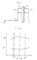
- An inlet port for an internal combustion engine in the first embodiment has a circular inlet hole 12 opened on a circular end face of a cylinder chamber 11 at an off-center position from its center towards the wall side.
- the inlet hole 12 is provided with an inlet valve 13 of popped valve type and connected to an inlet passage 15.
- the inlet passage 15 comprises a swirl generating section 16 which is connected to the inlet hole 12 and surrounds the inlet valve 13 at the end section of the inlet passage and an introducing section 19 which is the remaining section of the inlet passage excluding the end section.
- the wall surface of the swirl generating section 16 is formed by smoothly connecting two cylindrical surfaces facing to the peripheral surface of the valve stem 14.
- the width between the peripheral surface of the valve stem 14 and the wall surface of the swirl generating section 16 is wider at the outside part 17 on the wall side of the cylinder chamber 11 than at the inside part 18 on the center side of the cylinder chamber 11.
- the width is decreased gradually from the outside part 17 to the inside part 18 around the valve stem 14.
- the introducing section 19 is connected to the wider outside part 17 of the swirl generating section 16 along its tangential direction.
- the height from the opening face of the inlet hole 12 to the ceiling of the swirl generating section 16 is constant.
- the inlet air-stream through the inlet passage 15 flows from the introducing section 19 into the swirl generating section 16 and further flows through the inlet hole 12 into the cylinder chamber 11.
- the main stream of the inlet air flows from the center position of the introducing section 19 into the middle position between the wall surface of the outside part 17 of the swirl generating section 16 and the peripheral surface of the valve stem 14 and further flows through the inlet hole 12 to the cylinder chamber 11 along the tangential direction of the wall surface in the vicinity of the inlet hole 12 so as to produce the swirl circling along the wall surface of the cylinder chamber 11.
- the ratio w 1 w2 of the width of the outside part 17 and the inside part 18 was set to various values and then the strength of the swirl generating in the cylinder chamber 11, that is, the swirl ratio SR and the pressure loss AP of the inlet passage 15 were measured for each value of the width ratio w 1 /w z .
- the results are shown in the graph of Fig. 4. As shown in the upper section or lower of the graph, the swirl ratio SR becomes small and the pressure loss AP becomes large when the width ratio w i lw 2 is less than 1.1 or more than 2.8.
- the swirl ratio SR becomes larger and the pressure loss AP becomes smaller when the width ratio w i lw 2 is not less than 1.1 and not more than 2.8 ; and the strong swirl is generated under the high volume efficiency. Besides the better performance can be obtained when the width ratio w i /w 2 is not less than 1.15 and not more than 2.0.
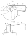
- An inlet port for an internal combustion engine in the second embodiment, as shown in Figs. 5 and 6, is composed similarly to that in the first embodiment. Moreover the center axis of the cylinder surface constituting the wall surface of the inside part 18 of the swirl generating section 16 coincides with the center axis of the inlet hole 12, while the center axis of the cylinder surface constituting the wall surface of the outside part 17 is off-centered from the center axis of the inlet hole 12 towards the wall surface of the outside part 17.
- the distance of the off-center, e is set to not less than 2% and not more than 50% of the diameter, d, of the inlet hole 12.
- the connecting angle between the outside part 17 and the introducing section 19 is set to an angle so that the main inlet stream from the introducing section 19 to the outside part 17 flows in between the wall surface of the outside part 17 and the peripheral surface of the valve stem 14 of the inlet valve 13.
- the distance, I, from the center axis of the inlet hole 12 to the center line of the introducing section 19 is set to not less than 20% and not more than 60% of the diameter, d, of the inlet hole 12.
- the introducing section 19 which has a rectangular cross section is formed in taper, and the minimum width, w, of the introducing- section is set to not less than 25% and not more than 85% of the diameter, d, of the inlet hole 12.
- the inlet air-stream through the inlet passage 15 flows from the introducing section 19 into the swirl generating section 16 and further flows through the inlet hole 12 into the cylinder chamber 11.
- the main stream of the inlet air flows from the center position of the introducing section 19 into the middle position between the wall surface of the outside part 17 of the swirl generating section 16 and the peripheral surface of the valve stem 14 and further flows through the inlet hole 12 to the cylinder chamber 11 along the tangential direction of the wall surface in the vicinity of the inlet hole 12 so as to produce the swirl circling along the wall surface of the cylinder chamber 11.
- the strong swirl is generated under the high volume efficiency.
- the off-center distance, e, at which the center axis of the cylinder surface constituting the wall surface of the outside part 17 of the swirl generating section 16 is off-centered from the center axis of the inlet hole 12 towards the wall surface of the outside part 17, is set to various values with respect to the diameter, d, of the inlet hole 12.
- the strength of the swirl generating in the cylinder 11, that is, the swirl ratio SR and the pressure loss AP of the inlet passage 15 were measured for each value of the off-center distance e. The results are shown by the solid line in the graph of Fig. 7.
- the swirl ratio SR is smaller and the pressure loss AP is larger, when the dimensionless off-center distance e/d is more than 0.5. Meanwhile the swirl ratio SR is smaller and the pressure loss AP is larger as the dimensionless off-center distance e/d is decreasing to less than 0.1.
- the decreasing rate of the swirl ratio SR and the increasing rate of the pressure loss AP become larger when the dimensionless off-center distance e/d is less than 0.02. Therefore, the swirl ratio SR is large and the pressure loss AP is small, when the dimensionless off-center distance e/d is not less than 0.02 and not more than 0.5 ; the strong swirl is generated under the high volume efficiency. Besides the better performance is acquired when the dimensionless off-center distance e/d is not less than 0.03 and not more than 0.3.
- the performance gets worse and the swirl ratio SR rapidly decreases and the pressure loss AP increases in the range of the dimensionless off-center e/d being less than 0.1, when the connecting angle between the outside part 17 and the introducing section 19 is set to an angle except the angle at which the main stream of the inlet air, passing from the introducing section 19 to the outside part 17, flows in between the wall surface of the outside part 17 and the peripheral surface of the valve stem 14.
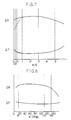
- the connecting angle, a, between the outside part 17 and the introducing section 19 is set to various values and the swirl ratio SR and the pressure loss AP were measured for each value of the angle a. The results are shown in the graph of Fig. 8.
- the connecting angle, a is, as shown in Fig. 5, the angle between the center line of the introducing section 19 and the connecting plane which contains both the connecting line of the wall surface of the inside part 18 to the inside wall of the introducing section 19, and the intersection line formed by the wall surface of the outside part 17 or the outside wall of the introducing section 19 and the plane rotating in 60 degrees around the center axis of the inlet hole 12 towards the outside part 17 from the plane containing the connecting line and the center axis of the inlet hole 12.
- the swirl ratio SR is much smaller and the pressure loss AP is larger when the connecting angle, a, is more than 135°.
- the swirl gets weaker because the main stream of the inlet air, which flows into the swirl generating section 16 from the introducing section 19, collides against the valve stem 14. Accordingly, the swirl ratio SR is large and the pressure loss AP is small when the connecting angle, a, is 135° or less. Besides the better performance is acquired when the connecting angle, a, is 110° or less.
- the swirl ratio SR drastically decreases and the pressure loss AP increases when the connecting angle, a, is less than 15° ; the swirl gets weaker because a part of the main stream of the inlet air, which flows into the outside part 17 of the swirl generating section 16 from the introducing section 19, collides against the wall surface of the outside part 17. Accordingly the swirl ratio SR is large and the pressure loss AP is small when the connecting angle, a, is set to the degree at which the main stream of the inlet air from the introducing section 19 to the outside part 17 flows in between the watt surface of the outside part 17 and the peripheral surface of the valve stem 14.
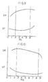
- the distance, I from the center axis of the inlet hole 12 to the center line of the introducing section 19 is set to various values with respect to the diamenter, d, of the inlet hole 12.
- the swirl ratio SR and the pressure loss AP were measured for each value of the distance I. The results are shown in the graph of Fig. 9. As the upper section or the lower of the graph shows, the swirl ratio SR is smaller and the pressure AP is larger when the dimensionless distance I/d is more than 0.6 or less than 0.2. Accordingly the swirl ratio SR is larger and the pressure loss AP is smaller when the dimensionless distance I/d is not less than 0.2 and not more than 0.6.
- the minimum width, w, of the introducing section 19 formed in taper is set to various values with respect to the diameter, d, of the inlet hole 12.
- the swirl ratio SR and the pressure loss AP were measured for each value of the minimum width w.
- the results are shown in the graph of Fig. 10. As the upper section or the lower of the graph shows, the swirl ratio SR is smaller and the pressure loss AP is larger when the dimensionless minimum width w/d is more than 0.85 or less than 0.25. Accordingly, the swirl ratio SR is larger and the pressure loss AP is smaller when the minimum width w/d is not less than 0.25 and not more than 0.85.
Landscapes
- Engineering & Computer Science (AREA)
- Chemical & Material Sciences (AREA)
- Combustion & Propulsion (AREA)
- Mechanical Engineering (AREA)
- General Engineering & Computer Science (AREA)
- Cylinder Crankcases Of Internal Combustion Engines (AREA)
Claims (7)
Applications Claiming Priority (4)
| Application Number | Priority Date | Filing Date | Title |
|---|---|---|---|
| JP151874/83 | 1983-08-19 | ||
| JP58151874A JPS6043124A (ja) | 1983-08-19 | 1983-08-19 | 内燃機関の吸気ポ−ト |
| JP58207964A JPS6098126A (ja) | 1983-11-04 | 1983-11-04 | 内燃機関の吸気ポ−ト |
| JP207964/83 | 1983-11-04 |
Publications (3)
| Publication Number | Publication Date |
|---|---|
| EP0134038A1 EP0134038A1 (de) | 1985-03-13 |
| EP0134038B1 EP0134038B1 (de) | 1988-03-16 |
| EP0134038B2 true EP0134038B2 (de) | 1991-06-12 |
Family
ID=26480979
Family Applications (1)
| Application Number | Title | Priority Date | Filing Date |
|---|---|---|---|
| EP84109887A Expired - Lifetime EP0134038B2 (de) | 1983-08-19 | 1984-08-20 | Einlasskanal für eine Brennkraftmaschine |
Country Status (3)
| Country | Link |
|---|---|
| US (1) | US4574751A (de) |
| EP (1) | EP0134038B2 (de) |
| DE (1) | DE3469937D1 (de) |
Families Citing this family (15)
| Publication number | Priority date | Publication date | Assignee | Title |
|---|---|---|---|---|
| US4745890A (en) * | 1986-10-01 | 1988-05-24 | General Motors Corporation | Engine with fluidic variable swirl port |
| US4873947A (en) * | 1988-02-22 | 1989-10-17 | Southwest Research Institute | Variable compression ratio direct injection engine |
| DE3924544A1 (de) * | 1989-07-25 | 1991-02-07 | Porsche Ag | Stroemungskanal |
| WO1992017701A1 (fr) * | 1991-03-28 | 1992-10-15 | Mitsubishi Jidosha Kogyo Kabushiki Kaisha | Structure de conduit d'admission pour moteur a combustion interne |
| JP3498334B2 (ja) * | 1993-11-08 | 2004-02-16 | 株式会社日立製作所 | 内燃機関の吸気装置 |
| DE4342139C1 (de) * | 1993-12-10 | 1995-09-28 | Hatz Motoren | Einzylinder-Dieselmotor |
| US5601062A (en) * | 1994-09-01 | 1997-02-11 | Hyundai Motor Company | Intake system for engine |
| JP3059346B2 (ja) * | 1994-10-19 | 2000-07-04 | リョービ株式会社 | 内燃機関の吸排気弁および吸気ポート |
| JP3562165B2 (ja) * | 1996-09-17 | 2004-09-08 | 日産自動車株式会社 | ディーゼルエンジンの吸気ポート |
| US6003485A (en) * | 1997-06-10 | 1999-12-21 | Nissan Motor Co., Ltd. | Helical intake port for an internal combustion engine |
| GB2332709A (en) * | 1997-12-24 | 1999-06-30 | Ford Global Tech Inc | I.c. engine inlet port with flat wall portion |
| GB2332708A (en) * | 1997-12-24 | 1999-06-30 | Ford Global Tech Inc | I.c. engine inlet port with sharp-edged swirl lip |
| US7077102B1 (en) * | 2005-01-17 | 2006-07-18 | Stowe John K | Dual inlet port for internal combustion engine |
| EP2467586B1 (de) * | 2009-08-20 | 2016-11-30 | Pinnacle Engines, Inc. | Wirbelmotor mit hoher frequenz |
| US9103277B1 (en) | 2014-07-03 | 2015-08-11 | Daniel Sexton Gurney | Moment-cancelling 4-stroke engine |
Family Cites Families (11)
| Publication number | Priority date | Publication date | Assignee | Title |
|---|---|---|---|---|
| GB374521A (en) * | 1931-03-12 | 1932-06-13 | Francis De Lautour | Improvements in four stroke cycle internal-combustion engines |
| US2920613A (en) * | 1956-12-12 | 1960-01-12 | Vogel Wolfgang | Swirl producing inlet port for internal combustion engine |
| US3020896A (en) * | 1959-08-07 | 1962-02-13 | Maschf Augsburg Nuernberg Ag | Cylinder head with air intake passages |
| DE2235050A1 (de) * | 1972-07-17 | 1974-01-31 | Elsbett | Drallbildender kanal, insbesondere im ansaugsystem von hubkolben-brennkraftmaschinen |
| AT336347B (de) * | 1973-06-08 | 1977-04-25 | List Hans | Brennkraftmaschine, insbesondere dieselmotor |
| GB1600888A (en) * | 1978-05-31 | 1981-10-21 | Ricardo Consulting Engs Ltd | Inlet ports in ic engines |
| JPS5920850B2 (ja) * | 1978-09-25 | 1984-05-16 | トヨタ自動車株式会社 | 内燃機関のヘリカル型吸気ポ−ト |
| JPS5546001A (en) * | 1978-09-25 | 1980-03-31 | Toyota Motor Corp | Helically shaped suction port for internal combustion engine |
| JPS5932647B2 (ja) * | 1978-09-25 | 1984-08-10 | トヨタ自動車株式会社 | 内燃機関のヘリカル型吸気ポ−ト |
| JPS5840647B2 (ja) * | 1978-10-19 | 1983-09-07 | トヨタ自動車株式会社 | 内燃機関の吸気装置 |
| JPS5932648B2 (ja) * | 1979-06-25 | 1984-08-10 | トヨタ自動車株式会社 | 内燃機関の吸気通路構造 |
-
1984
- 1984-08-07 US US06/638,616 patent/US4574751A/en not_active Expired - Fee Related
- 1984-08-20 EP EP84109887A patent/EP0134038B2/de not_active Expired - Lifetime
- 1984-08-20 DE DE8484109887T patent/DE3469937D1/de not_active Expired
Also Published As
| Publication number | Publication date |
|---|---|
| US4574751A (en) | 1986-03-11 |
| EP0134038A1 (de) | 1985-03-13 |
| EP0134038B1 (de) | 1988-03-16 |
| DE3469937D1 (en) | 1988-04-21 |
Similar Documents
| Publication | Publication Date | Title |
|---|---|---|
| EP0134038B2 (de) | Einlasskanal für eine Brennkraftmaschine | |
| US4529358A (en) | Vortex generating flow passage design for increased film cooling effectiveness | |
| JP4167457B2 (ja) | 油冷式圧縮機のレシーバタンク | |
| EP0724072A1 (de) | Brennkammer für Brennkraftmaschine | |
| JPS60235908A (ja) | 調節可能な円錐形噴霧器 | |
| EP0452494B1 (de) | Plasmabrenner für übertragenen lichtbogen | |
| CA1334838C (en) | Apparatus for separating solid particles from a fluid | |
| CA2215040A1 (en) | Centrifugal separator assembly and method for separating particles from hot gas | |
| US4693215A (en) | Inlet port for internal combustion engine | |
| US4678125A (en) | Nozzle | |
| EP0821616B1 (de) | Vorrichtung zum mischen einer ersten flüssigkeit in einer zweiten flüssigkeit | |
| JPS6085223A (ja) | 内燃機関の吸気ポ−ト | |
| JPH0533110B2 (de) | ||
| JPH0223691B2 (de) | ||
| CA1112633A (en) | Asymmetrical valve | |
| SU1019114A1 (ru) | Вихревой эжектор | |
| JPS59180027A (ja) | 内燃機関の吸気ポ−ト | |
| JPS6233570A (ja) | スプレ−ノズル | |
| JPH0253149U (de) | ||
| JPS59211717A (ja) | 内燃機関の吸気ポ−ト | |
| JPH0520564B2 (de) | ||
| KR100271823B1 (ko) | 평분사 노즐용 마우스피스 | |
| JPH0932704A (ja) | 燃料噴射装置 | |
| SU1317171A1 (ru) | Глушитель колебаний пульсирующего потока | |
| JP3358842B2 (ja) | 副室式機関の燃焼室 |
Legal Events
| Date | Code | Title | Description |
|---|---|---|---|
| PUAI | Public reference made under article 153(3) epc to a published international application that has entered the european phase |
Free format text: ORIGINAL CODE: 0009012 |
|
| AK | Designated contracting states |
Designated state(s): DE GB |
|
| 17P | Request for examination filed |
Effective date: 19850913 |
|
| 17Q | First examination report despatched |
Effective date: 19860409 |
|
| GRAA | (expected) grant |
Free format text: ORIGINAL CODE: 0009210 |
|
| AK | Designated contracting states |
Kind code of ref document: B1 Designated state(s): DE GB |
|
| REF | Corresponds to: |
Ref document number: 3469937 Country of ref document: DE Date of ref document: 19880421 |
|
| PLBI | Opposition filed |
Free format text: ORIGINAL CODE: 0009260 |
|
| PLBI | Opposition filed |
Free format text: ORIGINAL CODE: 0009260 |
|
| 26 | Opposition filed |
Opponent name: KLOECKNER-HUMBOLDT-DEUTZ AG Effective date: 19881126 |
|
| 26 | Opposition filed |
Opponent name: DAIMLER-BENZ AKTIENGESELLSCHAFT Effective date: 19881216 Opponent name: KLOECKNER-HUMBOLDT-DEUTZ AG Effective date: 19881126 |
|
| PGFP | Annual fee paid to national office [announced via postgrant information from national office to epo] |
Ref country code: GB Payment date: 19900813 Year of fee payment: 7 |
|
| PGFP | Annual fee paid to national office [announced via postgrant information from national office to epo] |
Ref country code: DE Payment date: 19900927 Year of fee payment: 7 |
|
| PUAH | Patent maintained in amended form |
Free format text: ORIGINAL CODE: 0009272 |
|
| STAA | Information on the status of an ep patent application or granted ep patent |
Free format text: STATUS: PATENT MAINTAINED AS AMENDED |
|
| 27A | Patent maintained in amended form |
Effective date: 19910612 |
|
| AK | Designated contracting states |
Kind code of ref document: B2 Designated state(s): DE GB |
|
| PG25 | Lapsed in a contracting state [announced via postgrant information from national office to epo] |
Ref country code: GB Effective date: 19910820 |
|
| GBPC | Gb: european patent ceased through non-payment of renewal fee | ||
| PG25 | Lapsed in a contracting state [announced via postgrant information from national office to epo] |
Ref country code: DE Effective date: 19920501 |