EP0133701B1 - Procédé et appareil pour botteler des objets allongés - Google Patents
Procédé et appareil pour botteler des objets allongés Download PDFInfo
- Publication number
- EP0133701B1 EP0133701B1 EP84109428A EP84109428A EP0133701B1 EP 0133701 B1 EP0133701 B1 EP 0133701B1 EP 84109428 A EP84109428 A EP 84109428A EP 84109428 A EP84109428 A EP 84109428A EP 0133701 B1 EP0133701 B1 EP 0133701B1
- Authority
- EP
- European Patent Office
- Prior art keywords
- length
- band
- band web
- cutter
- web
- Prior art date
- Legal status (The legal status is an assumption and is not a legal conclusion. Google has not performed a legal analysis and makes no representation as to the accuracy of the status listed.)
- Expired
Links
Images


Classifications
-
- B—PERFORMING OPERATIONS; TRANSPORTING
- B65—CONVEYING; PACKING; STORING; HANDLING THIN OR FILAMENTARY MATERIAL
- B65B—MACHINES, APPARATUS OR DEVICES FOR, OR METHODS OF, PACKAGING ARTICLES OR MATERIALS; UNPACKING
- B65B27/00—Bundling particular articles presenting special problems using string, wire, or narrow tape or band; Baling fibrous material, e.g. peat, not otherwise provided for
- B65B27/10—Bundling rods, sticks, or like elongated objects
-
- B—PERFORMING OPERATIONS; TRANSPORTING
- B29—WORKING OF PLASTICS; WORKING OF SUBSTANCES IN A PLASTIC STATE IN GENERAL
- B29C—SHAPING OR JOINING OF PLASTICS; SHAPING OF MATERIAL IN A PLASTIC STATE, NOT OTHERWISE PROVIDED FOR; AFTER-TREATMENT OF THE SHAPED PRODUCTS, e.g. REPAIRING
- B29C65/00—Joining or sealing of preformed parts, e.g. welding of plastics materials; Apparatus therefor
- B29C65/02—Joining or sealing of preformed parts, e.g. welding of plastics materials; Apparatus therefor by heating, with or without pressure
- B29C65/08—Joining or sealing of preformed parts, e.g. welding of plastics materials; Apparatus therefor by heating, with or without pressure using ultrasonic vibrations
-
- B—PERFORMING OPERATIONS; TRANSPORTING
- B29—WORKING OF PLASTICS; WORKING OF SUBSTANCES IN A PLASTIC STATE IN GENERAL
- B29C—SHAPING OR JOINING OF PLASTICS; SHAPING OF MATERIAL IN A PLASTIC STATE, NOT OTHERWISE PROVIDED FOR; AFTER-TREATMENT OF THE SHAPED PRODUCTS, e.g. REPAIRING
- B29C65/00—Joining or sealing of preformed parts, e.g. welding of plastics materials; Apparatus therefor
- B29C65/74—Joining or sealing of preformed parts, e.g. welding of plastics materials; Apparatus therefor by welding and severing, or by joining and severing, the severing being performed in the area to be joined, next to the area to be joined, in the joint area or next to the joint area
- B29C65/743—Joining or sealing of preformed parts, e.g. welding of plastics materials; Apparatus therefor by welding and severing, or by joining and severing, the severing being performed in the area to be joined, next to the area to be joined, in the joint area or next to the joint area using the same tool for both joining and severing, said tool being monobloc or formed by several parts mounted together and forming a monobloc
- B29C65/7443—Joining or sealing of preformed parts, e.g. welding of plastics materials; Apparatus therefor by welding and severing, or by joining and severing, the severing being performed in the area to be joined, next to the area to be joined, in the joint area or next to the joint area using the same tool for both joining and severing, said tool being monobloc or formed by several parts mounted together and forming a monobloc by means of ultrasonic vibrations
-
- B—PERFORMING OPERATIONS; TRANSPORTING
- B29—WORKING OF PLASTICS; WORKING OF SUBSTANCES IN A PLASTIC STATE IN GENERAL
- B29C—SHAPING OR JOINING OF PLASTICS; SHAPING OF MATERIAL IN A PLASTIC STATE, NOT OTHERWISE PROVIDED FOR; AFTER-TREATMENT OF THE SHAPED PRODUCTS, e.g. REPAIRING
- B29C66/00—General aspects of processes or apparatus for joining preformed parts
- B29C66/01—General aspects dealing with the joint area or with the area to be joined
- B29C66/05—Particular design of joint configurations
- B29C66/10—Particular design of joint configurations particular design of the joint cross-sections
- B29C66/11—Joint cross-sections comprising a single joint-segment, i.e. one of the parts to be joined comprising a single joint-segment in the joint cross-section
- B29C66/112—Single lapped joints
- B29C66/1122—Single lap to lap joints, i.e. overlap joints
-
- B—PERFORMING OPERATIONS; TRANSPORTING
- B29—WORKING OF PLASTICS; WORKING OF SUBSTANCES IN A PLASTIC STATE IN GENERAL
- B29C—SHAPING OR JOINING OF PLASTICS; SHAPING OF MATERIAL IN A PLASTIC STATE, NOT OTHERWISE PROVIDED FOR; AFTER-TREATMENT OF THE SHAPED PRODUCTS, e.g. REPAIRING
- B29C66/00—General aspects of processes or apparatus for joining preformed parts
- B29C66/01—General aspects dealing with the joint area or with the area to be joined
- B29C66/05—Particular design of joint configurations
- B29C66/306—Applying a mark during joining
- B29C66/3062—Applying a mark during joining in the form of letters or numbers
- B29C66/30621—Applying a mark during joining in the form of letters or numbers in the form of letters
-
- B—PERFORMING OPERATIONS; TRANSPORTING
- B29—WORKING OF PLASTICS; WORKING OF SUBSTANCES IN A PLASTIC STATE IN GENERAL
- B29C—SHAPING OR JOINING OF PLASTICS; SHAPING OF MATERIAL IN A PLASTIC STATE, NOT OTHERWISE PROVIDED FOR; AFTER-TREATMENT OF THE SHAPED PRODUCTS, e.g. REPAIRING
- B29C66/00—General aspects of processes or apparatus for joining preformed parts
- B29C66/01—General aspects dealing with the joint area or with the area to be joined
- B29C66/05—Particular design of joint configurations
- B29C66/306—Applying a mark during joining
- B29C66/3062—Applying a mark during joining in the form of letters or numbers
- B29C66/30623—Applying a mark during joining in the form of letters or numbers in the form of numbers
-
- B—PERFORMING OPERATIONS; TRANSPORTING
- B29—WORKING OF PLASTICS; WORKING OF SUBSTANCES IN A PLASTIC STATE IN GENERAL
- B29C—SHAPING OR JOINING OF PLASTICS; SHAPING OF MATERIAL IN A PLASTIC STATE, NOT OTHERWISE PROVIDED FOR; AFTER-TREATMENT OF THE SHAPED PRODUCTS, e.g. REPAIRING
- B29C66/00—General aspects of processes or apparatus for joining preformed parts
- B29C66/40—General aspects of joining substantially flat articles, e.g. plates, sheets or web-like materials; Making flat seams in tubular or hollow articles; Joining single elements to substantially flat surfaces
- B29C66/41—Joining substantially flat articles ; Making flat seams in tubular or hollow articles
- B29C66/43—Joining a relatively small portion of the surface of said articles
- B29C66/432—Joining a relatively small portion of the surface of said articles for making tubular articles or closed loops, e.g. by joining several sheets ; for making hollow articles or hollow preforms
- B29C66/4322—Joining a relatively small portion of the surface of said articles for making tubular articles or closed loops, e.g. by joining several sheets ; for making hollow articles or hollow preforms by joining a single sheet to itself
-
- B—PERFORMING OPERATIONS; TRANSPORTING
- B29—WORKING OF PLASTICS; WORKING OF SUBSTANCES IN A PLASTIC STATE IN GENERAL
- B29C—SHAPING OR JOINING OF PLASTICS; SHAPING OF MATERIAL IN A PLASTIC STATE, NOT OTHERWISE PROVIDED FOR; AFTER-TREATMENT OF THE SHAPED PRODUCTS, e.g. REPAIRING
- B29C66/00—General aspects of processes or apparatus for joining preformed parts
- B29C66/40—General aspects of joining substantially flat articles, e.g. plates, sheets or web-like materials; Making flat seams in tubular or hollow articles; Joining single elements to substantially flat surfaces
- B29C66/41—Joining substantially flat articles ; Making flat seams in tubular or hollow articles
- B29C66/43—Joining a relatively small portion of the surface of said articles
- B29C66/432—Joining a relatively small portion of the surface of said articles for making tubular articles or closed loops, e.g. by joining several sheets ; for making hollow articles or hollow preforms
- B29C66/4324—Joining a relatively small portion of the surface of said articles for making tubular articles or closed loops, e.g. by joining several sheets ; for making hollow articles or hollow preforms for making closed loops, e.g. belts
Definitions
- the present invention generally relates to an apparatus for bundling a number of elongate articles with a band according to the preamble of claim 1.
- the object of the invention is to improve the apparatus according to the preamble of claim 1 to the effect that the gripper mechanism has a simpler structure.
- the advantage to be achieved by the invention essentially consists in a simpler structure since opening of the gripper mechanism and feeding the band into this mechanism is effected by one single member, namely the presser arm.
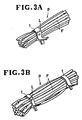
- Figure 1 shows an apparatus for bundling a number of elongate pieces or articles F such as slide fasteners with a bundling band t ( Figures 3A and 3B) of synthetic resin such as polyethylene or vinyl chloride, or laminated plastic of paper and synthetic resin, the apparatus being generally designated by the reference numeral 10.
- a bundling band t Figures 3A and 3B of synthetic resin such as polyethylene or vinyl chloride, or laminated plastic of paper and synthetic resin
- the apparatus 10 has an elongate channel- shaped bundle tray 11 positioned substantially centrally in the apparatus 10 for receiving a bundle of elongate articles F.
- a reel 12 is rotatably mounted by a shaft 13 on a support (not shown) and positioned upwardly of the bundle tray 11 on one side thereof, the reel 12 supports a roll of continuous band web T from which successive bands are cut off.
- a feed roller 14 is rotatably mounted by a shaft 14a on a base 15 for feeding the continuous band web T by a predetermined length in each cycle of operation of the bundling apparatus 10, the shaft 14a being coupled to a reversible motor (not shown). The feed roller 14 is positioned substantially directly below the reel 12.
- a band web guide 16 is vertically angularly movably mounted by a pin 17 on the base 15 below the feed roller 14.
- the band web guide 16 has a guide groove defined in an upper surface thereof and receiving a lower portion of the feed roller 14 loosely fitted therein.
- the guide groove is slightly wider than the band web T for guiding the same therein.
- the band web guide 16 is normally biased by a spring 18 to move toward the feed roller 14 for coacting therewith in supplying the band web T by a controlled length each time.
- a band web presser 19 is disposed below the feed roller 14 for laterally displacing the band web T as supplied from the feed roller 14.
- the band web pressure 19 comprises a horizontal presser arm 20 having a positioning recess 21 defined in a distal end thereof and extending from a vertical base 22 and an anvil 23 positioned below the presser arm 20 and extending from the base 22 parallel to the presser arm 20.
- a pair of horizontal pneumatic cylinders 27, 28 is supported on a cylinder support 29 and has a pair of respective piston rods 30, 31 connected respectively to the vertical bases 22, 26 for retractably moving the presser arm 20, the anvil 23, and the band web holder 24 toward a position over the bundle tray 11.
- a band web gripper 32 is positioned upwardly of the bundle tray 11 on an opposite side thereof in confronting relation to the presser arm 20.
- the band web gripper 32 includes a base 33 and a pair of gripping jaws 34, 35 pivotably mounted on the base 32 by pins 36, 37, respectively.
- the gripping jaws 34, 35 are normally biased toward each other by a spring 38 connected between the gripping jaws 34, 35 for gripping a free end of the band web T and a portion thereof that has been drawn by the band web presser arm 20, as will be described later.
- a vertical cutter 39 is vertically movably disposed above a rear end of the band web gripper 32 remote from the pins 36, 37 for cutting off a portion T 1 ( Figure 2E) of the band web T which projects from the rear end of the band web gripper 32.
- An ultrasonic horn 40 is positioned below the band web gripper 32 in confronting relation to the anvil 23 for fusing the band web T applied thereagainst by the anvil 23 which have moved toward the ultrasonic horn 40.
- the ultrasonic horn 40 is supported at a rear end thereof by a support arm 41.
- a horizontal bundle pusher 42 is horizontally movably supported at a rear end thereof on a piston rod 43 of an air cylinder (not shown). The horizontal bundle pusher 42 is retractably movable toward a position over the bundle tray 11.
- a printer 44 is positioned between the reel 12 and the feed roller 14 for marking various pieces of information such as a slide fastener type and a lot number on the bundle web T at spaced intervals therealong.
- a pair of hot air nozzles 45, 46 is disposed one on each side of the bundle tray 11 in mutually confronting relation for emitting hot air toward a finished bundle on the bundle tray 11.
- the bundle web T is made of a thermally shrinkable material, a bundle band will shrink around slide fasteners F upon application of hot air for stably and tightly bundling the slide fasteners F.
- a predetermined length of the band web T is unreeled by the feed roller 14 onto the bundle tray 11 substantially in the shape of a U with its free end gripped by the band web gripper 32.
- the presser arm 20, the anvil 23, the band web holder 24, and the bundle pusher 42 are in their retracted position as shown.
- Finished slide fasteners F are discharged by gravity from a fastener discharger H coupled to a slide fastener finishing machine (not shown) and positioned over the bundle tray 11 so that the slide fasteners F are placed on the band web T on the bundle tray 11, as illustrated in Figure 2B.
- the band web holder 24 is moved forward with the band web T received in the slot 25 ( Figure 1) to the position over the bundle tray 11, in which the band web holder 24 holds down the slide fasteners F extending across the band web T, as shown in Figure 2C.
- the presser arm 20 and the anvil 23 are moved forward.
- the presser arm 20 presses the band web T as folded forcibly between the gripping jaws 34, 35.
- the band web T is prevented by the band web holder 24 from being excessively pulled upwardly.
- the anvil 23 also presses portions of the band web T as it surrounds the slide fasteners F against the tip end of the ultrasonic horn 40.
- the ultrasonic horn 40 is now energized to fuse the band web T against the anvil 23 ( Figure 2D).
- the cutter 39 is then lowered to cut off a portion T1 of the band web T which projects from the rear end of the band web gripper 32, whereupon the length of the band web T disposed around the slide fasteners F is cut off from the band web T into a bundling band t as shown in Figure 2F.
- the band web holder 24 is retracted and at the same time the bundle pusher 42 is moved forward to push the bundling band t so that its end will be pulled off the band web gripper 32. At this time, an end of the band web T as supplied from the feed roller 14 remains gripped by the band web gripper 32.
- the band web T is made of a thermally shrinkable material, hot air is discharged from the hot air nozzles 45,46 against the bundling band t to cause the latter to shrink tightly around the slide fasteners F, thereby producing a bundled article p, as illustrated in Figure 2G.
- FIG 4 illustrates a bundling apparatus 50 according to another embodiment of the present invention.
- the apparatus 50 is basically the same as the apparatus 10 shown in Figure 1,.and only those components which differ from those of the apparatus 10 will be described below.
- the bundle tray 11 and the slide fastener discharger H are vertically spaced from each other with a bundling station S defined therebetween.
- the reel 12 for supplying the band web T and the printer 44 are mounted on a base 15a.
- the feed roller 14 and the band web guide 16 jointly constitute a band web feed mechanism A.
- a band web gripper E is composed of the gripping jaws 34, 35 having apertures 63, 64 ( Figure 7) defined vertically therethrough.
- a piercing needle 65 is located above the band web gripper E in vertical alignment with the apertures 63, 64.
- the piercing needle 65 is vertically movable by an air cylinder 66.
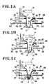
- FIGS 5A through 5H illustrate progressive steps of bundling operation of the apparatus 50.
- the steps shown in Figures 5A through 5H are substantially the same as those illustrated in Figures 2A through 2H. Only those operation modes which are different from the operation of Figures 2A through 2H will be described.
- the horizontal cutter 67 is moved into the slit 52 in the presser arm 51, cutting into the folded portion of the band web T, as illustrated in Figure 5E.
- the horizontal cutter 67 is more advantageous than the vertical cutter 39 ( Figure 1) in that there is no waste band web portion cut off.
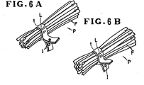
- the gripper E now grips an end T" of the band web T as supplied from the feed roller 14 and ends T' of a bundling hand t.
- the pierced end T" of the band web T remains gripped between the gripping jaws 34, 35. Since the piercing needle 65 is not actuated if there is a sufficient number of slide fasteners supplied, a next bundled article p has a band t having only one hole I in one of the ends thereof, as shown in Figure 6B. Therefore, the band t with one pierced hole only can be distinguished from the band which bundles an insufficient number of slide fasteners.
- the piercing needle 65 is preferably put into operation in the step shown in Figure 5F.
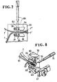
- Figure 8 shows a cutter mechanism according to still another embodiment of the invention.
- the cutter mechanism includes a cutter 70 drivable by an air cylinder 71 to move in a direction substantially perpendicularly to the direction in which the presser arm 51 is retractably movable.
- the cutter 70 tranversely cuts off the folded band web portion projecting from the gripping jaws 34, 35.
- the cutter mechanism of Figure 8 also does not produce any waste band web.
Claims (6)
Applications Claiming Priority (4)
| Application Number | Priority Date | Filing Date | Title |
|---|---|---|---|
| JP58147245A JPS6045120A (ja) | 1983-08-11 | 1983-08-11 | 長尺製品の結束仕上げ方法 |
| JP147245/83 | 1983-08-11 | ||
| JP59034694A JPS60183318A (ja) | 1984-02-25 | 1984-02-25 | 長尺製品の結束仕上げ装置 |
| JP34694/84 | 1984-02-25 |
Publications (3)
| Publication Number | Publication Date |
|---|---|
| EP0133701A2 EP0133701A2 (fr) | 1985-03-06 |
| EP0133701A3 EP0133701A3 (en) | 1986-03-26 |
| EP0133701B1 true EP0133701B1 (fr) | 1988-07-20 |
Family
ID=26373535
Family Applications (1)
| Application Number | Title | Priority Date | Filing Date |
|---|---|---|---|
| EP84109428A Expired EP0133701B1 (fr) | 1983-08-11 | 1984-08-08 | Procédé et appareil pour botteler des objets allongés |
Country Status (10)
| Country | Link |
|---|---|
| EP (1) | EP0133701B1 (fr) |
| KR (1) | KR870000994B1 (fr) |
| AU (1) | AU549864B2 (fr) |
| BR (1) | BR8404067A (fr) |
| CA (1) | CA1246431A (fr) |
| DE (1) | DE3472781D1 (fr) |
| GB (1) | GB2144705B (fr) |
| HK (1) | HK23789A (fr) |
| MY (1) | MY101585A (fr) |
| SG (1) | SG83288G (fr) |
Families Citing this family (12)
| Publication number | Priority date | Publication date | Assignee | Title |
|---|---|---|---|---|
| JPS62251319A (ja) * | 1986-04-24 | 1987-11-02 | ワイケイケイ株式会社 | 長尺製品の巻付結束仕上方法およびその装置 |
| JPS6347264A (ja) * | 1986-08-11 | 1988-02-29 | Yoshida Kogyo Kk <Ykk> | 長尺テ−プ状物の積重ね方法と装置 |
| DE3825715C1 (fr) * | 1988-07-28 | 1989-08-24 | Opti Patent-, Forschungs- Und Fabrikations-Ag, Riedern-Allmeind, Ch | |
| DE8910534U1 (fr) * | 1989-09-04 | 1991-01-17 | Luecke, Otto, 5600 Wuppertal, De | |
| IT1241222B (it) * | 1990-05-09 | 1993-12-29 | Irico S P A | Macchina automatica per la nastratura ed il taglio di fasci di fibre |
| FR2904968A1 (fr) * | 2006-08-21 | 2008-02-22 | Rangeard Patrick | Procede, dispositif et installation pour confectionner des paquets d'elements de longueurs |
| CN102616415B (zh) * | 2012-04-10 | 2014-02-26 | 余姚纺织机械有限公司 | 一种布卷的pe膜包装机 |
| CN106428727B (zh) * | 2013-10-15 | 2018-06-08 | 吕士进 | 一种棒型材打捆机器人的工作方法 |
| CN109732704B (zh) * | 2019-03-15 | 2021-04-16 | 常州市润腾超声波科技有限公司 | 一种超声波高速连续切带机控制方法 |
| CN110667909B (zh) * | 2019-08-19 | 2021-08-13 | 金鹏装配式建筑有限公司 | 一种便于移动的钢筋用捆扎装置 |
| CN110723355B (zh) * | 2019-10-08 | 2021-08-13 | 南京涵铭置智能科技有限公司 | 一种齿轴打包用保护膜抽出装置 |
| CN113428398B (zh) * | 2021-06-28 | 2022-09-27 | 兰剑智能科技股份有限公司 | 一种托盘防掉货捆扎设备及捆扎方法 |
Family Cites Families (5)
| Publication number | Priority date | Publication date | Assignee | Title |
|---|---|---|---|---|
| US3158973A (en) * | 1963-06-03 | 1964-12-01 | Serv All Machinery Corp | Packaging machine |
| US3670986A (en) * | 1970-12-29 | 1972-06-20 | Robert D Farkas | Supply reel for banding apparatus |
| DE2450373A1 (de) * | 1974-10-23 | 1976-04-29 | Bauer Eberhard | Maschine zum umhuellen von gegenstaenden mit kunststoff-folie |
| JPS5424199A (en) * | 1977-07-25 | 1979-02-23 | Japan Engine Valve Mfg | Tape banding device |
| US4482421A (en) * | 1982-06-02 | 1984-11-13 | Signode Corporation | Ultrasonic friction-fusion method and apparatus |
-
1984
- 1984-07-30 AU AU31295/84A patent/AU549864B2/en not_active Ceased
- 1984-08-03 GB GB08419868A patent/GB2144705B/en not_active Expired
- 1984-08-08 DE DE8484109428T patent/DE3472781D1/de not_active Expired
- 1984-08-08 EP EP84109428A patent/EP0133701B1/fr not_active Expired
- 1984-08-09 CA CA000460607A patent/CA1246431A/fr not_active Expired
- 1984-08-10 BR BR8404067A patent/BR8404067A/pt not_active IP Right Cessation
- 1984-08-10 KR KR1019840004784A patent/KR870000994B1/ko not_active IP Right Cessation
-
1987
- 1987-07-21 MY MYPI87001072A patent/MY101585A/en unknown
-
1988
- 1988-11-30 SG SG832/88A patent/SG83288G/en unknown
-
1989
- 1989-03-16 HK HK237/89A patent/HK23789A/xx not_active IP Right Cessation
Also Published As
| Publication number | Publication date |
|---|---|
| MY101585A (en) | 1991-12-17 |
| SG83288G (en) | 1989-04-14 |
| CA1246431A (fr) | 1988-12-13 |
| EP0133701A3 (en) | 1986-03-26 |
| HK23789A (en) | 1989-03-24 |
| KR870000994B1 (ko) | 1987-05-18 |
| AU549864B2 (en) | 1986-02-20 |
| GB2144705B (en) | 1987-05-13 |
| AU3129584A (en) | 1985-02-14 |
| GB8419868D0 (en) | 1984-09-05 |
| EP0133701A2 (fr) | 1985-03-06 |
| GB2144705A (en) | 1985-03-13 |
| KR850001881A (ko) | 1985-04-10 |
| BR8404067A (pt) | 1985-07-16 |
| DE3472781D1 (en) | 1988-08-25 |
Similar Documents
| Publication | Publication Date | Title |
|---|---|---|
| US4570422A (en) | Apparatus for bundling elongate articles | |
| EP0133701B1 (fr) | Procédé et appareil pour botteler des objets allongés | |
| US5092829A (en) | Method and apparatus for bundling and removing stacks of pieces cut from layups of sheet material | |
| EP0999558A2 (fr) | Fil électrique plat pour faisceau de fils et méthode et appareil de sa production | |
| US4342564A (en) | Apparatus for the stacking and connection of synthetic-resin foil bags | |
| US6103051A (en) | Continuous form sleeve blanks and apparatus for applying same | |
| US4610124A (en) | Method of bundling elongate articles | |
| KR0139832B1 (ko) | 테이프 카세트 및 그 테이프 카세트를 이용하는 열융합가능한 테이프 조각 자동 부착 장치 | |
| CA2373244A1 (fr) | Procede et appareil pour la fabrication d'un sachet en plastique a fond plat | |
| US3991542A (en) | Apparatus for banding a stack of articles | |
| US3962023A (en) | Apparatus for applying handles to plastic bags | |
| CA1180170A (fr) | Automatisme pour sectionner des conducteurs a longueur, les denuder et les garnir d'un connecteur en bout | |
| US3616086A (en) | Apparatus for marking textile article | |
| US5112289A (en) | Device for transverse cutting and welding of webs | |
| US4179063A (en) | Feed and severing apparatus | |
| US4548141A (en) | Apparatus for applying ribbon strips to a textile fabric | |
| JP2814371B2 (ja) | 袋体における吊下片付設方法及び装置 | |
| US6676315B1 (en) | Printing and delivery device for label tags | |
| JP3440813B2 (ja) | 多頭式端子帯供給装置 | |
| CN113954164B (zh) | 一种扎带自动裁切装置和方法 | |
| US4194340A (en) | Apparatus for packaging shoelaces: especially of the round type | |
| US5312317A (en) | Apparatus for detaching pieces of tube provided with transverse weld seams from a web and for stacking the same | |
| GB2271309A (en) | Bundling and labelling stacks of pieces cut from layups of sheet material | |
| JPH10319842A (ja) | 表示テープ片が連続して印刷されたテープの加工装置 | |
| JPH06290848A (ja) | 端子供給機構 |
Legal Events
| Date | Code | Title | Description |
|---|---|---|---|
| PUAI | Public reference made under article 153(3) epc to a published international application that has entered the european phase |
Free format text: ORIGINAL CODE: 0009012 |
|
| AK | Designated contracting states |
Designated state(s): BE CH DE FR IT LI NL SE |
|
| PUAL | Search report despatched |
Free format text: ORIGINAL CODE: 0009013 |
|
| AK | Designated contracting states |
Kind code of ref document: A3 Designated state(s): BE CH DE FR IT LI NL SE |
|
| 17P | Request for examination filed |
Effective date: 19860702 |
|
| 17Q | First examination report despatched |
Effective date: 19870422 |
|
| GRAA | (expected) grant |
Free format text: ORIGINAL CODE: 0009210 |
|
| AK | Designated contracting states |
Kind code of ref document: B1 Designated state(s): BE CH DE FR IT LI NL SE |
|
| ITF | It: translation for a ep patent filed |
Owner name: JACOBACCI & PERANI S.P.A. |
|
| REF | Corresponds to: |
Ref document number: 3472781 Country of ref document: DE Date of ref document: 19880825 |
|
| ET | Fr: translation filed | ||
| PLBE | No opposition filed within time limit |
Free format text: ORIGINAL CODE: 0009261 |
|
| STAA | Information on the status of an ep patent application or granted ep patent |
Free format text: STATUS: NO OPPOSITION FILED WITHIN TIME LIMIT |
|
| 26N | No opposition filed | ||
| ITTA | It: last paid annual fee | ||
| PGFP | Annual fee paid to national office [announced via postgrant information from national office to epo] |
Ref country code: SE Payment date: 19940504 Year of fee payment: 11 |
|
| PGFP | Annual fee paid to national office [announced via postgrant information from national office to epo] |
Ref country code: BE Payment date: 19940517 Year of fee payment: 11 |
|
| PGFP | Annual fee paid to national office [announced via postgrant information from national office to epo] |
Ref country code: CH Payment date: 19940804 Year of fee payment: 11 |
|
| PGFP | Annual fee paid to national office [announced via postgrant information from national office to epo] |
Ref country code: NL Payment date: 19940831 Year of fee payment: 11 |
|
| ITPR | It: changes in ownership of a european patent |
Owner name: CAMBIO RAGIONE SOCIALE;YKK CORPORATION |
|
| REG | Reference to a national code |
Ref country code: FR Ref legal event code: CD |
|
| EAL | Se: european patent in force in sweden |
Ref document number: 84109428.7 |
|
| PG25 | Lapsed in a contracting state [announced via postgrant information from national office to epo] |
Ref country code: SE Effective date: 19950809 |
|
| PG25 | Lapsed in a contracting state [announced via postgrant information from national office to epo] |
Ref country code: LI Effective date: 19950831 Ref country code: CH Effective date: 19950831 Ref country code: BE Effective date: 19950831 |
|
| BERE | Be: lapsed |
Owner name: YOSHIDA KOGYO K.K. Effective date: 19950831 |
|
| PG25 | Lapsed in a contracting state [announced via postgrant information from national office to epo] |
Ref country code: NL Effective date: 19960301 |
|
| REG | Reference to a national code |
Ref country code: CH Ref legal event code: PL |
|
| NLV4 | Nl: lapsed or anulled due to non-payment of the annual fee |
Effective date: 19960301 |
|
| EUG | Se: european patent has lapsed |
Ref document number: 84109428.7 |
|
| PGFP | Annual fee paid to national office [announced via postgrant information from national office to epo] |
Ref country code: FR Payment date: 20030808 Year of fee payment: 20 |
|
| PGFP | Annual fee paid to national office [announced via postgrant information from national office to epo] |
Ref country code: DE Payment date: 20030822 Year of fee payment: 20 |