EP0133009A2 - Zündverteiler für Brennkraftmaschine - Google Patents
Zündverteiler für Brennkraftmaschine Download PDFInfo
- Publication number
- EP0133009A2 EP0133009A2 EP84305015A EP84305015A EP0133009A2 EP 0133009 A2 EP0133009 A2 EP 0133009A2 EP 84305015 A EP84305015 A EP 84305015A EP 84305015 A EP84305015 A EP 84305015A EP 0133009 A2 EP0133009 A2 EP 0133009A2
- Authority
- EP
- European Patent Office
- Prior art keywords
- oxide
- rotor electrode
- ignition distributor
- specific resistance
- internal combustion
- Prior art date
- Legal status (The legal status is an assumption and is not a legal conclusion. Google has not performed a legal analysis and makes no representation as to the accuracy of the status listed.)
- Granted
Links
Images
Classifications
-
- F—MECHANICAL ENGINEERING; LIGHTING; HEATING; WEAPONS; BLASTING
- F02—COMBUSTION ENGINES; HOT-GAS OR COMBUSTION-PRODUCT ENGINE PLANTS
- F02P—IGNITION, OTHER THAN COMPRESSION IGNITION, FOR INTERNAL-COMBUSTION ENGINES; TESTING OF IGNITION TIMING IN COMPRESSION-IGNITION ENGINES
- F02P7/00—Arrangements of distributors, circuit-makers or -breakers, e.g. of distributor and circuit-breaker combinations or pick-up devices
- F02P7/02—Arrangements of distributors, circuit-makers or -breakers, e.g. of distributor and circuit-breaker combinations or pick-up devices of distributors
- F02P7/021—Mechanical distributors
- F02P7/025—Mechanical distributors with noise suppression means specially adapted for the distributor
Definitions
- This invention relates to an ignition distributor for internal combustion engine, and more particularly to an ignition distributor for internal combustion engine with reduced generation of radio noises.
- radio noise generation sources is an electric discharge at the ignition distributor for the internal combustion engine.
- Another attempt is to provide a resistor or a dielectric as projected at the tip end of the metallic rotor electrode, where a precursor electric discharge takes place between the resistor or the dielectric and the stationary electrode, and the main electric discharge then takes place therebetween. That is, the electric discharge energy can be reduced, but no effect on oscillation suppression of the main electric discharge current can be obtained, and a less effect on reduction in the radio noise generation can be attained.
- An object of the present invention is to provide an ignition distributor for an internal combustion engine with less electric discharge energy and reduced radio noise generation.
- an ignition distributor for an internal combustion engine is characterized by using a sintered mixture comprising zirconium oxide and at least one electroconductive inorganic compound having a specific resistance of not more than 10 6 ⁇ cm as a rotor electrode, and more preferably characterized in that the sintered mixture has a specific resistance of 10 to 10 6 ⁇ cm at room temperature.
- the sintered mixture may contain a small amount of a sintering aid to improve the sintering ability.
- At least one of nitrides, borides, carbides and silicides of transition elements of groups IIIa, VIa, Va and VIa of the periodic table more specifically, Y, Ti, Zr, Hf, V, Nb, Ta, Cr, Mo, W, etc., or metal oxide semi-conductors, more specifically.
- TiO 2 , Nb 2 O 3 , V 2 O 5 , MoO 2 , CdO, ZnO, SnO 2 , Fe 3 0 4 , Ta 2 O 5 , CoO, Cu 2 0, Cr 2 O 3 , SnO, MnO, NiO, W0 3 , etc. or double oxides having an improved electroconductivity, for example, BaTiO 3 , SrTi0 3 , etc. can be used.
- Such sintered mixture contains high resistance regions comprising zirconium oxide and conductive regions in mixture. Effects of using such a sintered mixture as a rotor electrode will be explained as follows.
- the accumulated electric charges on the high resistance regions at the surface increase the local electric field and lowers the discharge voltage, resulting in reduced electric discharge energy.
- the high frequency current is controlled by the relatively high resistance effect of rotor electrode to suppress the radio noise generation.
- the specific resistance of sintered mixture is 10 to 10 6 ⁇ cm. With too low a specific resistance, no better resistance effect can be obtained, whereas with too high a specific resistance the rotor electrode turns electrically insulating, and can no more play a role of electrode.
- the sintered mixture contains 40-95% by volume of these oxides in total and 60-5% by volume of zirconium oxide (Zr0 2 ). It is particularly preferable that a ratio of ZnO to Zr0 2 by volume is 7:3 and the sintered mixture further contains a specific resistance-controlling agent.
- the specific resistance-controlling agent can be exemplified by antimony oxide (Sb 2 O 3 ), aluminum oxide (Al 2 O 3 ), titanium oxide (TiO 2 ) and magnesium oxide (MgO).
- Silicon oxide Si0 2
- ZnAl 2 O 4 Co A1204, NiAl 2 O 4 , Zn 2 SiO 4 , Co 2 SiO 4 , Ni 2 SiO 4 , etc.
- Zr0 2 Zinc oxide
- the sintered mixture for use in the present invention can be prepared by mixing raw material powders, molding the mixture, and sintering the molded mixture by means of hot press or pressureless sintering.
- the sintered mixture When the sintered mixture is used as a rotor electrode, it can be easily mass-produced at low cost, because there is no necessity for combining with other parts of different material.
- the sintered mixture for use in the present invention contains ZrO 2 as a component, and thus has a high mechanical strength. Furthermore, it contains the inorganic compound as described above as the electroconductive component, and thus has a good chemical stability and a long durability.
- Zr0 2 is less reactive to other oxides during the sintering than A1 2 0 3 , and thus the desired sintered mixture can be obtained stably.
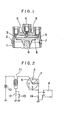
- Fig. 1 shows a vertical cross-sectional view of an ignition distributor for an internal combustion engine according to one embodiment of the present invention.
- a plurality of stationary electrodes 3 arranged substantially in a circle.
- the stationary electrodes 3 are connected to ignition plugs provided in a plurality of cylinders in an internal combustion engine.
- a slidable contact rod 6 is provided at the center on the inside surface of cap 2 through a central terminal 4 and a conductive spring 5.
- a plate-formed rotor electrode in contact with the contact rod 6 under a pressing force by the spring 5 is fixed to the surface of an insulating substrate 8, and the tip end of rotor electrode 7 faces the sides at the tip ends of stationary electrodes 3 through a small clearance.
- the insulating substrate 8 and the rotor electrode 7 rotate together with a cam shaft 9, and when the rotor electrode 7 comes to a position facing the stationary electrode 3, an electric discharge takes place between the rotor electrode 7, to which a high voltage is applied from the central terminal 4, and the stationary electrode 3 to allow an electric passage therebetween. At this moment, a high voltage is applied to an ignition plug connected to said stationary electrode 3.
- Powder of zirconium oxide (Zr0 2 ) and powder of aluminum oxide (Al 2 0 3 ) were mixed together in various mixing ratios, and further MgO and Y 2 0 3 as sintering aids and other transition element compounds were added thereto.
- the resulting powdery mixture was molded under a pressure of 1,000 kg/cm 2 , and sintered in an argon gas under one atmosphere at a temperature of 1,580°C for one hour.
- Rotor electrodes were prepared from the resulting sintered mixtures and mounted on ignition distributors for internal combustion engines.
- the electric noise current generated in the ignition distributors provided with the thus prepared rotor electrodes was measured in the following manner.
- the individual terminals of aluminum stationary electrodes were earthed through a resistor, and an electric discharge current was passed to the earth through the resistor. Both ends of the resistor were connected to the input terminals of a noise-meter and the noise components generated by the electric discharge were measured by the noise-meter.
- the measuring circuit is shown in Fig. 2.
- a battery 10 is connected to the primary side of an induction coil 11, and other terminal of induction coil 11 is earthed through a condenser 12.
- the condenser 12 is connected with a primary contact 13 in parallel.
- the secondary side of induction coil 11 is connected to the central terminal 4, which is further connected to the rotor electrode 7 through the contact rod.
- the stationary electrodes 3 are arranged in a circle around the rotor electrode 7 through a small clearance, and the individual terminals of stationary electrodes 3 are earthed through a resistor 14. Both ends of resistor 14 are connected to the input terminals of the noise-meter 15.
- the stationary electrodes 3 are made of aluminum.
- Sintered mixtures of Al 2 O 3 , Zr0 2 and various semi-conductor oxides were prepared in the similar manner as in Example 1 and ignition distributors for internal combustion engines were assembled, using the sintered mixtures as rotor electrodes. Then, the electric noise current was measured in the similar manner as in Example 1. Compositions and specific resistance of sintered mixtures and results of measurement of electric noise current, based on the conventional brass rotor electrode as a reference, are shown in Table 2.
- Antimony oxide (Sb 2 0 3 ) was added to zinc oxide (ZnO) powder in a ratio of the former to the latter of 4% by volume, and further zirconium oxide (Zr0 2 ) was added thereto in various mixing ratios.
- the resulting powdery mixtures were molded under a pressure of 1,000 kg/cm 2 and then sintered in the air at a temperature of 1,300°C for 3 hours.
- Rotor electrodes were prepared from the resulting sintered mixtures and mounted on ignition distributors for internal combustion engines, as shown in Fig. 1.
- compositions and specific resistances of sintered mixtures, and results of measurement of electric noise current based on the conventional brass rotor electrode as the reference are shown in Table 3. As is evident from the results, the resistance is too high when the sintered mixture contains less than 40% by volume of ZnO, and thus the sintered mixture cannot be used as a rotor electrode.
- composition A of cobalt oxide (CoO) powder containing 0.1% by mole of lithium carbonate (Li 2 C0 3 ) on the basis of cobalt oxide and composition B of nickel oxide (NiO) powder containing 7% by mole of lithium carbonate (Li 2 CO 3 ) on the basis of nickel oxide were prepared. These mixtures were each mixed with Zr0 2 in various mixing ratios, and the resulting mixtures were molded and sintered at a temperature of 1,350°C for 3 hours. Rotor electrodes were prepared from the sintered mixtures, and noise electric current was measured in the similar manner as in Example 1.
- compositions and specific resistance of sintered mixtures and results of measurement of electric noise current are shown in Table 4.
- the sintering mixture contains less than 40% by volume of composition A or B, the resistance is so high that it cannot be used as a rotor electrode. It has been found by X-ray diffraction that lithium carbonate is decomposed during the sintering and diffused into cobalt oxide or nickel oxide, and that the compositions A and B consist essentially of CoO and NiO, respectively. As is evident from the results, a high noise-suppressing effect of more than 10 dB can be obtained, when the sintered mixture contains 40 to 95% by volume of composition A or B.
- Example 3 Still further sintered mixture compositions were investigated according to Example 3.
- a sintered mixture of 70 vol.% ZnO-25 vol.% ZrO 2 -5 vol.% MgO (sample No. 33) had an electric noise current of -15 dB, when prepared into a rotor electrode
- a sintered mixture of 70 vol.% ZnO-10 vol.% NiO-20 vol% ZrO 2 samples No. 34 had an electric noise current of -18 dB when prepared into a rotor electrode.
- the conventional brass rotor electrode as
- Sintered mixtures having compositions shown in Table 5 were prepared by molding under a pressure of 1,0 0 0 kg/cm 2 and sintered in the air at 1,300°C for 3 hours, and prepared into rotor electrodes.
- the specific resistance at 20°C and electric noise current thereof are shown in Table 5.
Landscapes
- Engineering & Computer Science (AREA)
- Chemical & Material Sciences (AREA)
- Combustion & Propulsion (AREA)
- Mechanical Engineering (AREA)
- General Engineering & Computer Science (AREA)
- Ignition Installations For Internal Combustion Engines (AREA)
Applications Claiming Priority (2)
| Application Number | Priority Date | Filing Date | Title |
|---|---|---|---|
| JP138106/83 | 1983-07-27 | ||
| JP58138106A JPS6030475A (ja) | 1983-07-27 | 1983-07-27 | 内燃機関用配電器 |
Publications (3)
| Publication Number | Publication Date |
|---|---|
| EP0133009A2 true EP0133009A2 (de) | 1985-02-13 |
| EP0133009A3 EP0133009A3 (en) | 1986-04-09 |
| EP0133009B1 EP0133009B1 (de) | 1992-10-21 |
Family
ID=15214086
Family Applications (1)
| Application Number | Title | Priority Date | Filing Date |
|---|---|---|---|
| EP84305015A Expired EP0133009B1 (de) | 1983-07-27 | 1984-07-24 | Zündverteiler für Brennkraftmaschine |
Country Status (4)
| Country | Link |
|---|---|
| US (1) | US4581501A (de) |
| EP (1) | EP0133009B1 (de) |
| JP (1) | JPS6030475A (de) |
| DE (1) | DE3485961T2 (de) |
Families Citing this family (2)
| Publication number | Priority date | Publication date | Assignee | Title |
|---|---|---|---|---|
| JPS61149575A (ja) * | 1984-12-20 | 1986-07-08 | Nippon Denso Co Ltd | 内燃機関の点火配電器 |
| JPS63170574U (de) * | 1987-04-28 | 1988-11-07 |
Family Cites Families (9)
| Publication number | Priority date | Publication date | Assignee | Title |
|---|---|---|---|---|
| CH344108A (de) * | 1955-12-23 | 1960-01-31 | Bosch Gmbh Robert | Mittel zur Vermeidung von Störungen in Geräten der drahtlosen Nachrichtenübermittlung und Bildübertragung durch elektrische Anlagen von Kraftfahrzeugen |
| US4217470A (en) * | 1977-07-06 | 1980-08-12 | Robert Bosch Gmbh | Ignition distributor with noise suppression electrodes |
| US4166201A (en) * | 1978-01-09 | 1979-08-28 | General Motors Corporation | Ignition distributor electrode for suppressing radio frequency interference |
| US4165452A (en) * | 1978-01-09 | 1979-08-21 | General Motors Corporation | Ignition distributor electrode for suppressing radio frequency interference |
| FR2435612A2 (fr) * | 1978-09-09 | 1980-04-04 | Bosch Gmbh Robert | Dispositif pour la distribution de la tension d'allumage dans des installations d'allumage destinees a des moteurs a combustion interne |
| US4224068A (en) * | 1978-09-14 | 1980-09-23 | General Motors Corporation | Method of making distributor rotor electrode containing dielectric bodies for suppressing radio frequency interference |
| US4369343A (en) * | 1979-11-26 | 1983-01-18 | Nissan Motor Co., Ltd. | Ignition distributor having electrodes with thermistor discharging portions |
| JPS5823278A (ja) * | 1981-08-03 | 1983-02-10 | Nissan Motor Co Ltd | 内燃機関用配電器 |
| JPS57140563A (en) * | 1981-02-25 | 1982-08-31 | Nissan Motor Co Ltd | Ignition distributor for internal combustion engine |
-
1983
- 1983-07-27 JP JP58138106A patent/JPS6030475A/ja active Pending
-
1984
- 1984-07-24 EP EP84305015A patent/EP0133009B1/de not_active Expired
- 1984-07-24 DE DE8484305015T patent/DE3485961T2/de not_active Expired - Fee Related
- 1984-07-25 US US06/634,049 patent/US4581501A/en not_active Expired - Fee Related
Also Published As
| Publication number | Publication date |
|---|---|
| JPS6030475A (ja) | 1985-02-16 |
| US4581501A (en) | 1986-04-08 |
| DE3485961D1 (de) | 1992-11-26 |
| DE3485961T2 (de) | 1993-04-01 |
| EP0133009B1 (de) | 1992-10-21 |
| EP0133009A3 (en) | 1986-04-09 |
Similar Documents
| Publication | Publication Date | Title |
|---|---|---|
| EP0087004B1 (de) | Keramische Zusammensetzung und Kondensator hergestellt mit dieser keramischen Zusammensetzung | |
| US4217470A (en) | Ignition distributor with noise suppression electrodes | |
| EP0157276B1 (de) | Keramische Zusammensetzung mit nichtlinearem spannungsabhängigem Widerstand | |
| US6184769B1 (en) | Monolithic varistor | |
| EP0437613B1 (de) | Halbleiterkeramikkondensator von laminiertem und zwischenkornisolationstyp und verfahren zu seiner herstellung | |
| JPH11340009A (ja) | 非直線抵抗体 | |
| EP0316015B1 (de) | Material für Widerstände und daraus hergestellter nichtlinearer Widerstand | |
| EP0412167B1 (de) | Halbleiterkeramikkondensator von dem laminierten typ mit zwischenkornisolation und verfahren zu seiner herstellung | |
| EP0429653B1 (de) | Keramischer kondensator eines halbleitertyps mit laminierten und kornisolierten grenzschichten | |
| EP0133009A2 (de) | Zündverteiler für Brennkraftmaschine | |
| US4475091A (en) | Composite function element and process for producing the same | |
| CN115732147A (zh) | 压敏电阻器及其制造方法 | |
| KR19990077593A (ko) | 반도체세라믹및이로부터제조되는전자부품 | |
| EP0133008B1 (de) | Zündverteiler für Brennkraftmaschine | |
| JP4360154B2 (ja) | 誘電体磁器組成物およびその製造方法、ならびにセラミック電子部品 | |
| JPS5823278A (ja) | 内燃機関用配電器 | |
| JP2660010B2 (ja) | 高誘電率磁器組成物及びセラミックコンデンサ | |
| JPS6128759A (ja) | 内燃機関用配電器 | |
| GB2161985A (en) | Ignition distribution for internal combustion engines | |
| JP3239719B2 (ja) | 電圧非直線抵抗体の製造方法 | |
| KR840002488B1 (ko) | 조립식 저항기용 소재의 제조법 | |
| JP2001052907A (ja) | セラミック素子とその製造方法 | |
| JPS6349073B2 (de) | ||
| JPH04368B2 (de) | ||
| JP3631786B2 (ja) | 電圧非直線抵抗体の製造方法 |
Legal Events
| Date | Code | Title | Description |
|---|---|---|---|
| PUAI | Public reference made under article 153(3) epc to a published international application that has entered the european phase |
Free format text: ORIGINAL CODE: 0009012 |
|
| 17P | Request for examination filed |
Effective date: 19840823 |
|
| AK | Designated contracting states |
Designated state(s): DE FR GB |
|
| PUAL | Search report despatched |
Free format text: ORIGINAL CODE: 0009013 |
|
| AK | Designated contracting states |
Kind code of ref document: A3 Designated state(s): DE FR GB |
|
| 17Q | First examination report despatched |
Effective date: 19900104 |
|
| GRAA | (expected) grant |
Free format text: ORIGINAL CODE: 0009210 |
|
| AK | Designated contracting states |
Kind code of ref document: B1 Designated state(s): DE FR GB |
|
| REF | Corresponds to: |
Ref document number: 3485961 Country of ref document: DE Date of ref document: 19921126 |
|
| ET | Fr: translation filed | ||
| PLBE | No opposition filed within time limit |
Free format text: ORIGINAL CODE: 0009261 |
|
| STAA | Information on the status of an ep patent application or granted ep patent |
Free format text: STATUS: NO OPPOSITION FILED WITHIN TIME LIMIT |
|
| 26N | No opposition filed | ||
| PGFP | Annual fee paid to national office [announced via postgrant information from national office to epo] |
Ref country code: FR Payment date: 19950516 Year of fee payment: 12 |
|
| PGFP | Annual fee paid to national office [announced via postgrant information from national office to epo] |
Ref country code: GB Payment date: 19950714 Year of fee payment: 12 |
|
| PGFP | Annual fee paid to national office [announced via postgrant information from national office to epo] |
Ref country code: DE Payment date: 19950926 Year of fee payment: 12 |
|
| PG25 | Lapsed in a contracting state [announced via postgrant information from national office to epo] |
Ref country code: GB Effective date: 19960724 |
|
| GBPC | Gb: european patent ceased through non-payment of renewal fee |
Effective date: 19960724 |
|
| PG25 | Lapsed in a contracting state [announced via postgrant information from national office to epo] |
Ref country code: FR Effective date: 19970328 |
|
| PG25 | Lapsed in a contracting state [announced via postgrant information from national office to epo] |
Ref country code: DE Effective date: 19970402 |
|
| REG | Reference to a national code |
Ref country code: FR Ref legal event code: ST |