EP0132884A2 - Vorrichtung zum Beseitigen von Dampf in Haushaltswaschmaschinen - Google Patents
Vorrichtung zum Beseitigen von Dampf in Haushaltswaschmaschinen Download PDFInfo
- Publication number
- EP0132884A2 EP0132884A2 EP84201043A EP84201043A EP0132884A2 EP 0132884 A2 EP0132884 A2 EP 0132884A2 EP 84201043 A EP84201043 A EP 84201043A EP 84201043 A EP84201043 A EP 84201043A EP 0132884 A2 EP0132884 A2 EP 0132884A2
- Authority
- EP
- European Patent Office
- Prior art keywords
- tub
- steam
- water
- drawer
- pipe
- Prior art date
- Legal status (The legal status is an assumption and is not a legal conclusion. Google has not performed a legal analysis and makes no representation as to the accuracy of the status listed.)
- Granted
Links
- 238000005406 washing Methods 0.000 title claims abstract description 16
- XLYOFNOQVPJJNP-UHFFFAOYSA-N water Substances O XLYOFNOQVPJJNP-UHFFFAOYSA-N 0.000 claims abstract description 28
- 239000003795 chemical substances by application Substances 0.000 claims abstract description 10
- 230000005494 condensation Effects 0.000 abstract 1
- 238000009833 condensation Methods 0.000 abstract 1
- 101150114468 TUB1 gene Proteins 0.000 description 6
- 238000005054 agglomeration Methods 0.000 description 1
- 230000002776 aggregation Effects 0.000 description 1
- 230000005540 biological transmission Effects 0.000 description 1
- 238000010276 construction Methods 0.000 description 1
- 238000001816 cooling Methods 0.000 description 1
- 239000000498 cooling water Substances 0.000 description 1
- 239000003599 detergent Substances 0.000 description 1
- 238000007599 discharging Methods 0.000 description 1
- 230000000694 effects Effects 0.000 description 1
- 238000010438 heat treatment Methods 0.000 description 1
- 238000011065 in-situ storage Methods 0.000 description 1
- 230000007774 longterm Effects 0.000 description 1
Images


Classifications
-
- D—TEXTILES; PAPER
- D06—TREATMENT OF TEXTILES OR THE LIKE; LAUNDERING; FLEXIBLE MATERIALS NOT OTHERWISE PROVIDED FOR
- D06F—LAUNDERING, DRYING, IRONING, PRESSING OR FOLDING TEXTILE ARTICLES
- D06F39/00—Details of washing machines not specific to a single type of machines covered by groups D06F9/00 - D06F27/00
- D06F39/06—Arrangements for preventing or destroying scum
Definitions
- This invention relates to a device for suppressing steam in domestic washing machines which comprise a drawer or similar container means for the wash agents, which is connected hydraulically to a tub in which the drum carrying the laundry is rotatably supported, and water delivery means associated with the drawer in order to discharge the wash agents into the tub through said hydraulic connection.
- a drawer or similar container means for the wash agents which is connected hydraulically to a tub in which the drum carrying the laundry is rotatably supported, and water delivery means associated with the drawer in order to discharge the wash agents into the tub through said hydraulic connection.
- the object of the present invention is to effectively and largely suppress the steam which generates in the tub during washing, by the use of simple means.
- a device which is characterized essentially in that a syphon is disposed in the hydraulic connection between the drawer and tub, and in that a steam vent pipe is provided connected to the tub, and is water-cooled over at least one portion so as to constitute a steam condenser.
- the vent pipe extends into the drawer itself, into a water-filled chamber which is situated in proximity to the water delivery means, so as to receive a fraction thereof.
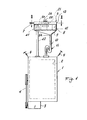
- the reference numeral 1 indicates the conventional tub of a washing machine.
- the drum 2 into which the laundry to be washed is placed, is cantilever-mounted rotatably inside the tub.
- the drum is driven by an electric motor 3 by way of a belt transmission 4.
- the tub is suspended from a load-bearing frame, not shown, by means of springs 5.
- the washing machine comprises a device, indicated overall by 6 and for simplicity defined in the present description by the term "drawer”, into which the wash agents (detergents, softeners etc.) are placed, and are discharged into the tub 1 by the water flowing from the water main through the pipe 7 and a solenoid valve, not shown.
- the wash agents detergents, softeners etc.
- the drawer 6 comprises a lower casing 8 possessing an inclined base 9 which converges towards a pipe stub 8A on which is mounted the end of a flexible pipe 10 which terminates on the tub 1, at a suitable aperture provided in the tub shell.
- the pipe 10 comprises a syphon 11, in which a plug of water forms and remains, its purpose being to prevent the steam generated in the tub during washing from escaping outwards through the drawer 6.
- the drawer also comprises an extractable part 12 possessing a set of compartments 12a, b, c .... in which the washing agents used in the wash cycle are placed in their required quantities.
- the lower casing 8 is closed upperly by a cover 13, which comprises a set of tubes 14a, b ...., which terminate above the compartments 12a, 12b .... and serve to feed these latter with the water necessary for removing the products used during washing (see Figure 2).
- said tubes terminate in mutually aligned apertures (again see Figure 2) in front of which, and aligned therewith, are provided nozzles 15a, b, c ... provided on the stationary pipe 7, which is connected to the water main.
- a substantially cylindrical guide 16 (see Figure 3) which is in one piece with the cover and is provided with a longitudinal slot 17 facing the inlets of the tubes 14a, b ....
- the guide in question is open lowerly at 18 to allow water to discharge to the lower casing 8 and from here into the tub 1 through the pipe 10.
- the tubular guide 16 also upperly comprises a longitudinal slot 19 to allow the movement of a peg 20 associated with a distributor 21 which is slidably mounted in said guide 16.
- the distributor is of approximately cylindrical configuration, and comprises an outlet port 22 disposed in the slot 17 of the guide 16 in front of the mouths of the tubes 14a, b, c ...
- the distributor 21 also comprises side walls provided with a slot 23 in order not to interfere with the nozzles 15a, b ... or with the pipe 7 during its movements...
- the peg 20 is disposed between the arms of a fork provided at the end of a lever 24 which is pivoted at 25 and is made to adhere, by means of a spring 26, to a cam 27 rigid with the exit shaft 29 of the normal washing machine programmer (timer) 28.
- the distributor 21 can be operated in any other known manner, such as that described in Italian patent 863,831.
- One or two nozzles 15a, b, c ... come into communication with one or two inlets of the pipes 14a, b, c... by way of the port 22, in accordance with the position assumed by the distributor 21 at any given time.
- the other nozzles, which do not face the port 22, discharge their water into the underlying casing 8, and part of this water reaches a lateral chamber 40, into which there extends the outlet stub 41 of a flexible vent pipe 42 connected to the tub 1.
- Said chamber 40 is bounded by walls 43 rigid with the lower casing 8 of the drawer, and comprises an overflow edge 44 for discharging the excess water which reaches it when the water feed pipe 7 is opened.
- the outlet stub 41 also forms a single piece with the lower casing 8 of the drawer, and on it there is disposed ( Figure 5) a deflector member or angle plate indicated overall by 50 and provided lowerly with a series of elastic stems 51 which are disposed spaced-apart along a cylindrical surface and elastically clamp against the upper part of the outlet stub 41 in order to removably retain said angle plate 50 in situ.
- the angle plate comprises two substantially converging surfaces 52 and a rib 53, by which it can be gripped for its removal or its fitting to the end of the outlet stub 41.
- the purpose of the angle plate 50 is to deflect any still uncondensed steam leaving the outlet stub 41, towards ,and on to the surface of the water contained in the chamber 40 (see also Figure 4).
- the operation is easily apparent from the aforegoing description.
- the water is fed, according to requirements, into the predetermined compartments 12a, b ... of the drawer 6, in accordance with the position of the distributor 21 relative to the fixed nozzles 15a, b ... Part of the water penetrates into the compartments, removes the wash agents and is discharged from one end of said compartments, for example as shown in Figure 1 of French patent 1,601,628.
- this water containing the entrained wash agent meets the water from the other nozzles 15a, b, c ..., this latter having directly reached said base without passing through the compartments.
- a certain quantity of this latter water also enters the chamber 40 to replace that already present, and the excess of this water is discharged over the overflow edge 44 and on to the inclined base 9. All these water streams flow through the pipe 10 and syphon 11 and into the tub 1.
- the uncondensed steam which emerges below the angle plate 50 is directed by this latter on to the free surface of the water contained in the chamber 40 (because of the converging inclined surface configuration of the angle plate), so that it is further suppressed. In this manner, there is substantially no escape of steam into the room in which the washing machine is situated.
Landscapes
- Engineering & Computer Science (AREA)
- Textile Engineering (AREA)
- Detail Structures Of Washing Machines And Dryers (AREA)
- Cleaning By Liquid Or Steam (AREA)
Applications Claiming Priority (2)
| Application Number | Priority Date | Filing Date | Title |
|---|---|---|---|
| IT22268/83A IT1164324B (it) | 1983-07-27 | 1983-07-27 | Dispositivo per l'abbattimento del vapore nelle macchine lavabiancheria domestiche |
| IT2226883 | 1983-07-27 |
Publications (3)
| Publication Number | Publication Date |
|---|---|
| EP0132884A2 true EP0132884A2 (de) | 1985-02-13 |
| EP0132884A3 EP0132884A3 (en) | 1985-11-13 |
| EP0132884B1 EP0132884B1 (de) | 1989-04-26 |
Family
ID=11193911
Family Applications (1)
| Application Number | Title | Priority Date | Filing Date |
|---|---|---|---|
| EP84201043A Expired EP0132884B1 (de) | 1983-07-27 | 1984-07-12 | Vorrichtung zum Beseitigen von Dampf in Haushaltswaschmaschinen |
Country Status (4)
| Country | Link |
|---|---|
| EP (1) | EP0132884B1 (de) |
| AR (1) | AR230460A1 (de) |
| DE (1) | DE3477945D1 (de) |
| IT (1) | IT1164324B (de) |
Cited By (9)
| Publication number | Priority date | Publication date | Assignee | Title |
|---|---|---|---|---|
| FR2573781A1 (fr) * | 1984-11-23 | 1986-05-30 | Philips Nv | Distributeur d'eau a vanne a coulisse pour des tiroirs a produits de lavage de machines a laver |
| ES2066675A2 (es) * | 1992-07-21 | 1995-03-01 | Mayc Sa | Mejoras en los dispositivos antirrebosamiento de agua en cubas de lavadoras. |
| US7753009B2 (en) | 2006-10-19 | 2010-07-13 | Whirlpool Corporation | Washer with bio prevention cycle |
| US7904981B2 (en) | 2006-08-15 | 2011-03-15 | Whirlpool Corporation | Water supply control for a steam generator of a fabric treatment appliance |
| US7913339B2 (en) | 2006-08-15 | 2011-03-29 | Whirlpool Corporation | Water supply control for a steam generator of a fabric treatment appliance using a temperature sensor |
| WO2020156045A1 (zh) * | 2019-01-29 | 2020-08-06 | 青岛海尔滚筒洗衣机有限公司 | 洗涤设备 |
| CN111575985A (zh) * | 2020-04-27 | 2020-08-25 | 海信(山东)冰箱有限公司 | 洗干一体机 |
| US10844533B2 (en) | 2007-05-07 | 2020-11-24 | Whirlpool Corporation | Method for controlling a household washing machine |
| US20230213210A1 (en) * | 2022-01-06 | 2023-07-06 | Whirlpool Corporation | Water fill drawer with structures to prevent backflow of steam |
Families Citing this family (16)
| Publication number | Priority date | Publication date | Assignee | Title |
|---|---|---|---|---|
| US7765628B2 (en) | 2006-06-09 | 2010-08-03 | Whirlpool Corporation | Steam washing machine operation method having a dual speed spin pre-wash |
| US7941885B2 (en) | 2006-06-09 | 2011-05-17 | Whirlpool Corporation | Steam washing machine operation method having dry spin pre-wash |
| US7627920B2 (en) | 2006-06-09 | 2009-12-08 | Whirlpool Corporation | Method of operating a washing machine using steam |
| US7730568B2 (en) | 2006-06-09 | 2010-06-08 | Whirlpool Corporation | Removal of scale and sludge in a steam generator of a fabric treatment appliance |
| US7591859B2 (en) | 2006-08-15 | 2009-09-22 | Whirlpool Corporation | Water supply control for a steam generator of a fabric treatment appliance using a weight sensor |
| US7886392B2 (en) | 2006-08-15 | 2011-02-15 | Whirlpool Corporation | Method of sanitizing a fabric load with steam in a fabric treatment appliance |
| US7665332B2 (en) | 2006-08-15 | 2010-02-23 | Whirlpool Corporation | Steam fabric treatment appliance with exhaust |
| US7841219B2 (en) | 2006-08-15 | 2010-11-30 | Whirlpool Corporation | Fabric treating appliance utilizing steam |
| US7861343B2 (en) | 2007-08-31 | 2011-01-04 | Whirlpool Corporation | Method for operating a steam generator in a fabric treatment appliance |
| US8555676B2 (en) | 2007-08-31 | 2013-10-15 | Whirlpool Corporation | Fabric treatment appliance with steam backflow device |
| US7966683B2 (en) | 2007-08-31 | 2011-06-28 | Whirlpool Corporation | Method for operating a steam generator in a fabric treatment appliance |
| US8037565B2 (en) | 2007-08-31 | 2011-10-18 | Whirlpool Corporation | Method for detecting abnormality in a fabric treatment appliance having a steam generator |
| US7690062B2 (en) | 2007-08-31 | 2010-04-06 | Whirlpool Corporation | Method for cleaning a steam generator |
| US8555675B2 (en) | 2007-08-31 | 2013-10-15 | Whirlpool Corporation | Fabric treatment appliance with steam backflow device |
| US7918109B2 (en) | 2007-08-31 | 2011-04-05 | Whirlpool Corporation | Fabric Treatment appliance with steam generator having a variable thermal output |
| US7905119B2 (en) | 2007-08-31 | 2011-03-15 | Whirlpool Corporation | Fabric treatment appliance with steam generator having a variable thermal output |
Family Cites Families (5)
| Publication number | Priority date | Publication date | Assignee | Title |
|---|---|---|---|---|
| FR1170651A (fr) * | 1957-04-05 | 1959-01-16 | Perfectionnement apporté aux machines à laver | |
| DE1460838B2 (de) * | 1963-06-28 | 1971-07-22 | Kondensiervorrichtung fuer daempfe und schaeume an einer trommel waschmaschine | |
| DE1760809A1 (de) * | 1968-07-04 | 1972-01-05 | Siemens Elektrogeraete Gmbh | Waeschebehandlungsmaschine |
| DE1807968B2 (de) * | 1968-11-09 | 1973-03-22 | G. Bauknecht Gmbh, Elektrotechnische Fabriken, 7000 Stuttgart | Dampfkondensationsvorrichtung fuer eine trommelwaschmaschine |
| DE2410107C3 (de) * | 1974-03-02 | 1979-01-18 | Hermann Zanker Kg, Maschinen- Und Metallwarenfabrik, 7400 Tuebingen | Waschmaschine mit Kondensator |
-
1983
- 1983-07-27 IT IT22268/83A patent/IT1164324B/it active
-
1984
- 1984-02-23 AR AR295809A patent/AR230460A1/es active
- 1984-07-12 DE DE8484201043T patent/DE3477945D1/de not_active Expired
- 1984-07-12 EP EP84201043A patent/EP0132884B1/de not_active Expired
Cited By (12)
| Publication number | Priority date | Publication date | Assignee | Title |
|---|---|---|---|---|
| FR2573781A1 (fr) * | 1984-11-23 | 1986-05-30 | Philips Nv | Distributeur d'eau a vanne a coulisse pour des tiroirs a produits de lavage de machines a laver |
| ES2066675A2 (es) * | 1992-07-21 | 1995-03-01 | Mayc Sa | Mejoras en los dispositivos antirrebosamiento de agua en cubas de lavadoras. |
| US7904981B2 (en) | 2006-08-15 | 2011-03-15 | Whirlpool Corporation | Water supply control for a steam generator of a fabric treatment appliance |
| US7913339B2 (en) | 2006-08-15 | 2011-03-29 | Whirlpool Corporation | Water supply control for a steam generator of a fabric treatment appliance using a temperature sensor |
| US7753009B2 (en) | 2006-10-19 | 2010-07-13 | Whirlpool Corporation | Washer with bio prevention cycle |
| US10844533B2 (en) | 2007-05-07 | 2020-11-24 | Whirlpool Corporation | Method for controlling a household washing machine |
| US11993886B2 (en) | 2007-05-07 | 2024-05-28 | Whirlpool Corporation | Method for controlling a household washing machine |
| WO2020156045A1 (zh) * | 2019-01-29 | 2020-08-06 | 青岛海尔滚筒洗衣机有限公司 | 洗涤设备 |
| JP2022519183A (ja) * | 2019-01-29 | 2022-03-22 | 青島海爾▲滾▼筒洗衣机有限公司 | 洗濯設備 |
| CN111575985A (zh) * | 2020-04-27 | 2020-08-25 | 海信(山东)冰箱有限公司 | 洗干一体机 |
| US20230213210A1 (en) * | 2022-01-06 | 2023-07-06 | Whirlpool Corporation | Water fill drawer with structures to prevent backflow of steam |
| US12529481B2 (en) * | 2022-01-06 | 2026-01-20 | Whirlpool Corporation | Water fill drawer with structures to prevent backflow of steam |
Also Published As
| Publication number | Publication date |
|---|---|
| IT1164324B (it) | 1987-04-08 |
| EP0132884A3 (en) | 1985-11-13 |
| AR230460A1 (es) | 1984-04-30 |
| EP0132884B1 (de) | 1989-04-26 |
| IT8322268A0 (it) | 1983-07-27 |
| IT8322268A1 (it) | 1985-01-27 |
| DE3477945D1 (en) | 1989-06-01 |
Similar Documents
| Publication | Publication Date | Title |
|---|---|---|
| EP0132884A2 (de) | Vorrichtung zum Beseitigen von Dampf in Haushaltswaschmaschinen | |
| US5588313A (en) | Automatic washing machine fitted for drying | |
| EP1561853B1 (de) | Vorrichtung zur Vermeidung von Flüssigkeitsüberlauf bei einer Waschmaschine | |
| CA2497506C (en) | Detergent dispenser for a washing machine | |
| EP0240910A2 (de) | Wasch- und Trockenmaschine | |
| RU95117707A (ru) | Автоматическая, предназначенная для сушки, стиральная машина | |
| US10422073B2 (en) | Laundry washing machine equipped with a treating agents dispenser having water supplying apparatus | |
| US3757543A (en) | Combination detergent dispenser and manual filter | |
| AU2005200380B2 (en) | Detergent-supply system and washing machine using the same | |
| EP0552843B1 (de) | Waschtrockner mit einer Sicherheitsvorrichtung gegen Wasserverschmutzung | |
| EP0959171A1 (de) | Waschmaschine | |
| GB2022622A (en) | Improvements in detergent feeders for clothes washing machines | |
| NZ215572A (en) | Automatic washing/drying machine; increased water flow through heated air condenser during washing cycle flushes out lint deposits | |
| CA1047364A (en) | Liquid flow mechanical diverter valve | |
| CA1096190A (en) | Additive dispensing system | |
| EP0125627B1 (de) | Waschmitteleinspülvorrichtung für eine Waschmaschine | |
| KR101474433B1 (ko) | 세탁기의 세제 공급 장치 | |
| CN116103889A (zh) | 冲入系统、导水的家用器具和用于引导流体的方法 | |
| US4205540A (en) | Washing machine additive dispenser with siphon starter | |
| KR0126122Y1 (ko) | 드럼세탁기용 압력제거 및 자연배수방지 장치 | |
| WO2003023119A1 (en) | Laundry appliance | |
| US3005329A (en) | Laundry machine overflow construction | |
| EP2706139A1 (de) | Verbesserungen an einer Abflusskreisfilteranordnung für Waschvorrichtungen | |
| KR100271740B1 (ko) | 드럼세탁기의 유연제 투입장치 | |
| KR0120629Y1 (ko) | 빨래판이 내장된 세탁기 |
Legal Events
| Date | Code | Title | Description |
|---|---|---|---|
| PUAI | Public reference made under article 153(3) epc to a published international application that has entered the european phase |
Free format text: ORIGINAL CODE: 0009012 |
|
| AK | Designated contracting states |
Designated state(s): DE FR GB IT SE |
|
| PUAL | Search report despatched |
Free format text: ORIGINAL CODE: 0009013 |
|
| AK | Designated contracting states |
Designated state(s): DE FR GB IT SE |
|
| 17P | Request for examination filed |
Effective date: 19860429 |
|
| 17Q | First examination report despatched |
Effective date: 19871120 |
|
| GRAA | (expected) grant |
Free format text: ORIGINAL CODE: 0009210 |
|
| AK | Designated contracting states |
Kind code of ref document: B1 Designated state(s): DE FR GB IT SE |
|
| REF | Corresponds to: |
Ref document number: 3477945 Country of ref document: DE Date of ref document: 19890601 |
|
| RAP2 | Party data changed (patent owner data changed or rights of a patent transferred) |
Owner name: WHIRLPOOL INTERNATIONAL B.V. Owner name: IRE INDUSTRIE RIUNITE EURODOMESTICI S.P.A. |
|
| ITF | It: translation for a ep patent filed | ||
| ET | Fr: translation filed | ||
| PLBE | No opposition filed within time limit |
Free format text: ORIGINAL CODE: 0009261 |
|
| STAA | Information on the status of an ep patent application or granted ep patent |
Free format text: STATUS: NO OPPOSITION FILED WITHIN TIME LIMIT |
|
| 26N | No opposition filed | ||
| PGFP | Annual fee paid to national office [announced via postgrant information from national office to epo] |
Ref country code: SE Payment date: 19920720 Year of fee payment: 9 |
|
| PG25 | Lapsed in a contracting state [announced via postgrant information from national office to epo] |
Ref country code: SE Effective date: 19930713 |
|
| EUG | Se: european patent has lapsed |
Ref document number: 84201043.1 Effective date: 19940210 |
|
| PGFP | Annual fee paid to national office [announced via postgrant information from national office to epo] |
Ref country code: DE Payment date: 19960926 Year of fee payment: 13 |
|
| PGFP | Annual fee paid to national office [announced via postgrant information from national office to epo] |
Ref country code: GB Payment date: 19970703 Year of fee payment: 14 |
|
| PGFP | Annual fee paid to national office [announced via postgrant information from national office to epo] |
Ref country code: FR Payment date: 19970709 Year of fee payment: 14 |
|
| PG25 | Lapsed in a contracting state [announced via postgrant information from national office to epo] |
Ref country code: DE Free format text: LAPSE BECAUSE OF NON-PAYMENT OF DUE FEES Effective date: 19980401 |
|
| PG25 | Lapsed in a contracting state [announced via postgrant information from national office to epo] |
Ref country code: GB Free format text: LAPSE BECAUSE OF NON-PAYMENT OF DUE FEES Effective date: 19980712 |
|
| GBPC | Gb: european patent ceased through non-payment of renewal fee |
Effective date: 19980712 |
|
| PG25 | Lapsed in a contracting state [announced via postgrant information from national office to epo] |
Ref country code: FR Free format text: LAPSE BECAUSE OF NON-PAYMENT OF DUE FEES Effective date: 19990331 |
|
| REG | Reference to a national code |
Ref country code: FR Ref legal event code: ST |