EP0131955A1 - Procédé et installation pour le traitement thermique d'objets cylindriques, en particulier de tubes, notamment fait de matériaux céramiques - Google Patents
Procédé et installation pour le traitement thermique d'objets cylindriques, en particulier de tubes, notamment fait de matériaux céramiques Download PDFInfo
- Publication number
- EP0131955A1 EP0131955A1 EP84108379A EP84108379A EP0131955A1 EP 0131955 A1 EP0131955 A1 EP 0131955A1 EP 84108379 A EP84108379 A EP 84108379A EP 84108379 A EP84108379 A EP 84108379A EP 0131955 A1 EP0131955 A1 EP 0131955A1
- Authority
- EP
- European Patent Office
- Prior art keywords
- transport
- temperature
- chamber
- zone
- tubes
- Prior art date
- Legal status (The legal status is an assumption and is not a legal conclusion. Google has not performed a legal analysis and makes no representation as to the accuracy of the status listed.)
- Granted
Links
- 238000000034 method Methods 0.000 title claims abstract description 14
- 229910010293 ceramic material Inorganic materials 0.000 title claims abstract description 9
- 238000007669 thermal treatment Methods 0.000 title 1
- 238000010438 heat treatment Methods 0.000 claims abstract description 46
- 238000005245 sintering Methods 0.000 claims abstract description 10
- 238000011144 upstream manufacturing Methods 0.000 claims description 12
- 230000001419 dependent effect Effects 0.000 claims description 3
- 230000002093 peripheral effect Effects 0.000 claims description 2
- 238000001816 cooling Methods 0.000 abstract description 17
- 238000001035 drying Methods 0.000 abstract description 5
- 230000032258 transport Effects 0.000 description 37
- 238000006073 displacement reaction Methods 0.000 description 4
- 238000007664 blowing Methods 0.000 description 2
- 239000000919 ceramic Substances 0.000 description 2
- 239000000463 material Substances 0.000 description 2
- 238000007493 shaping process Methods 0.000 description 2
- 244000068988 Glycine max Species 0.000 description 1
- 238000005192 partition Methods 0.000 description 1
- 230000005855 radiation Effects 0.000 description 1
- 238000000638 solvent extraction Methods 0.000 description 1
- 229910001220 stainless steel Inorganic materials 0.000 description 1
- 239000010935 stainless steel Substances 0.000 description 1
- 229920001169 thermoplastic Polymers 0.000 description 1
- 239000012815 thermoplastic material Substances 0.000 description 1
- 239000004416 thermosoftening plastic Substances 0.000 description 1
- 238000010792 warming Methods 0.000 description 1
Images

Classifications
-
- C—CHEMISTRY; METALLURGY
- C04—CEMENTS; CONCRETE; ARTIFICIAL STONE; CERAMICS; REFRACTORIES
- C04B—LIME, MAGNESIA; SLAG; CEMENTS; COMPOSITIONS THEREOF, e.g. MORTARS, CONCRETE OR LIKE BUILDING MATERIALS; ARTIFICIAL STONE; CERAMICS; REFRACTORIES; TREATMENT OF NATURAL STONE
- C04B33/00—Clay-wares
- C04B33/32—Burning methods
-
- C—CHEMISTRY; METALLURGY
- C04—CEMENTS; CONCRETE; ARTIFICIAL STONE; CERAMICS; REFRACTORIES
- C04B—LIME, MAGNESIA; SLAG; CEMENTS; COMPOSITIONS THEREOF, e.g. MORTARS, CONCRETE OR LIKE BUILDING MATERIALS; ARTIFICIAL STONE; CERAMICS; REFRACTORIES; TREATMENT OF NATURAL STONE
- C04B35/00—Shaped ceramic products characterised by their composition; Ceramics compositions; Processing powders of inorganic compounds preparatory to the manufacturing of ceramic products
- C04B35/622—Forming processes; Processing powders of inorganic compounds preparatory to the manufacturing of ceramic products
- C04B35/64—Burning or sintering processes
-
- C—CHEMISTRY; METALLURGY
- C21—METALLURGY OF IRON
- C21D—MODIFYING THE PHYSICAL STRUCTURE OF FERROUS METALS; GENERAL DEVICES FOR HEAT TREATMENT OF FERROUS OR NON-FERROUS METALS OR ALLOYS; MAKING METAL MALLEABLE, e.g. BY DECARBURISATION OR TEMPERING
- C21D9/00—Heat treatment, e.g. annealing, hardening, quenching or tempering, adapted for particular articles; Furnaces therefor
- C21D9/08—Heat treatment, e.g. annealing, hardening, quenching or tempering, adapted for particular articles; Furnaces therefor for tubular bodies or pipes
-
- F—MECHANICAL ENGINEERING; LIGHTING; HEATING; WEAPONS; BLASTING
- F27—FURNACES; KILNS; OVENS; RETORTS
- F27B—FURNACES, KILNS, OVENS, OR RETORTS IN GENERAL; OPEN SINTERING OR LIKE APPARATUS
- F27B9/00—Furnaces through which the charge is moved mechanically, e.g. of tunnel type; Similar furnaces in which the charge moves by gravity
- F27B9/14—Furnaces through which the charge is moved mechanically, e.g. of tunnel type; Similar furnaces in which the charge moves by gravity characterised by the path of the charge during treatment; characterised by the means by which the charge is moved during treatment
- F27B9/20—Furnaces through which the charge is moved mechanically, e.g. of tunnel type; Similar furnaces in which the charge moves by gravity characterised by the path of the charge during treatment; characterised by the means by which the charge is moved during treatment the charge moving in a substantially straight path tunnel furnace
- F27B9/201—Furnaces through which the charge is moved mechanically, e.g. of tunnel type; Similar furnaces in which the charge moves by gravity characterised by the path of the charge during treatment; characterised by the means by which the charge is moved during treatment the charge moving in a substantially straight path tunnel furnace walking beam furnace
- F27B9/208—Furnaces through which the charge is moved mechanically, e.g. of tunnel type; Similar furnaces in which the charge moves by gravity characterised by the path of the charge during treatment; characterised by the means by which the charge is moved during treatment the charge moving in a substantially straight path tunnel furnace walking beam furnace the workpieces being rotated during their advance
-
- F—MECHANICAL ENGINEERING; LIGHTING; HEATING; WEAPONS; BLASTING
- F27—FURNACES; KILNS; OVENS; RETORTS
- F27B—FURNACES, KILNS, OVENS, OR RETORTS IN GENERAL; OPEN SINTERING OR LIKE APPARATUS
- F27B9/00—Furnaces through which the charge is moved mechanically, e.g. of tunnel type; Similar furnaces in which the charge moves by gravity
- F27B9/14—Furnaces through which the charge is moved mechanically, e.g. of tunnel type; Similar furnaces in which the charge moves by gravity characterised by the path of the charge during treatment; characterised by the means by which the charge is moved during treatment
- F27B9/20—Furnaces through which the charge is moved mechanically, e.g. of tunnel type; Similar furnaces in which the charge moves by gravity characterised by the path of the charge during treatment; characterised by the means by which the charge is moved during treatment the charge moving in a substantially straight path tunnel furnace
- F27B9/24—Furnaces through which the charge is moved mechanically, e.g. of tunnel type; Similar furnaces in which the charge moves by gravity characterised by the path of the charge during treatment; characterised by the means by which the charge is moved during treatment the charge moving in a substantially straight path tunnel furnace being carried by a conveyor
- F27B9/243—Endless-strand conveyor
Definitions
- the invention relates to a method for the heat treatment of cylindrical bodies, in particular tubes, in particular made of ceramic material, which are transported in a horizontal position through different temperature zones during the heat treatment and are rotated about their own axes at least on the part of the transport path with the highest temperature.
- the invention further relates to a system for carrying out such a method, which consists of several, one behind the other chambers with heating devices and transport means for the transport of the cylindrical body in a horizontal position through the chambers.
- the heat treatment of the tubes in such furnaces is unfavorable for various reasons. Since the tubes are heated mainly from the outside by radiant heat from the furnace roof and the walls of the furnace, but the heat conduction of the tube wall is poor for most ceramic materials, it takes a relatively long time to bring the tubes to the desired temperature on the inside are. Long treatment times require long ovens and are therefore unfavorable for the heat economy. If one tried to roll the tubes along the entire transport route in order to obtain more uniform heating or cooling over the entire circumference from the beginning, there would be a risk that the tubes would move axially on the stove floor and hit the walls. In addition, in this case the transport speed would depend on the speed of rotation which is directly dependent on uniform heating and would thus determine the length of the treatment zone for a given length of stay in the individual zone.
- the invention has for its object to provide a method and a system that enables the heat treatment of cylindrical, elongated bodies with greater effectiveness.
- This object is achieved procedurally in that the cylindrical bodies are rotated around their own axes during the entire transport through the individual heat zones at a peripheral speed that is independent of the transport speed and sufficiently large to be able to stay in the a individual zones to ensure uniform heating and cooling, if necessary, and to prevent deformation of the body taking into account the temperature-dependent dimensional rigidity of the body.
- this object is achieved in that the transport means in the individual zones have driven support elements with which the bodies can be rotated about their own axes in the respective zone independently of the transport speed.
- the bodies to be heated are rotated about their own axes during the heat treatment, it is ensured that they are heated uniformly over the circumference, so that time for temperature compensation between regions of the circumference that are heated to a greater or lesser extent is not required. This makes it possible to heat up faster. A faster warming of the body allows a shorter treatment zone.
- the heat treatment can be further accelerated by supplying the heat not only from the outside but also from the inside. This can be done, for example, by blowing hot air or cooling air into the interior of the tubes. Preferably, the blowing in takes place alternately from opposite ends on the transport path in order to supply the heat as evenly as possible from the inside.
- the heat can also be generated by means of a heating element that can be inserted axially into the tubes.
- a heating element that can be inserted axially into the tubes.
- Such heating is particularly useful in the treatment zone with the highest temperature (sintering zone), in which the tubes are treated stationary but with higher self-rotation to prevent deformation of the thermoplastic material.
- the heat treatment takes place in the temperature zone with the highest temperature in such a way that the treatment temperature of this zone is raised from the temperature at the end of the upstream treatment zone to the desired maximum temperature and then up to the temperature at the beginning of the next one Treatment zone is lowered.
- This refinement of the invention makes it possible to treat the bodies to be heat-treated in a very short zone which therefore requires little thermal energy.
- Another advantage of such a method is that high-quality and therefore also expensive, high-temperature-resistant ceramic material is required only for this small temperature zone, while for the other, larger zones with the lower temperatures of up to e.g. Max. 800 C, cheaper material, namely normal stainless steel, can be used.
- the heat treatment takes place in the temperature zone with the highest treatment temperature in a space which is separated from the upstream and downstream zones.
- This configuration has the advantage that the heat treatment section remains short and no temperature compensation zone is required, which should consist of high-quality, high-temperature-resistant material and additionally entails heat loss.
- Both of the lengths of the transport paths of the bodies through the zones required for the heat treatment and also with regard to the heat balance for the heat treatment is advantageous if the bodies are transported to and from the heat treatment zone with the highest temperature in parallel, in particular one above the other, whereby A heat exchange takes place between the objects of one transport line and the other, opposite transport line.
- the heat exchange is preferably carried out by air conducted past the bodies. This heat exchange is particularly effective when the air is directed past the transport lines in counterflow.
- the transport means are endless belts or chains with driven support rollers or support arms in a manner known per se (US Pat. No. 2,481,130).
- What is not known per se is the further embodiment of the invention in that one strand of the belt or chain runs through a chamber upstream of the treatment zone with the highest temperature and the opposite strand of the belt or chain runs through a chamber which is correspondingly wide the treatment zone with the highest temperature.
- This configuration leads both to a compact design and also enables the possibility of heat exchange between the two chambers with appropriate management of the atmosphere of the chambers.
- the chambers arranged one behind the other in the transport direction can be laterally offset from one another and their transport means can be arranged to overlap one another.
- the elongated bodies horizontally transported in the transverse position can be pushed axially from the transport means of one chamber onto the transport means of the other chamber.
- heat treatment zones are arranged upstream of the zone with the highest temperature, for example a drying chamber and a heating chamber in front of the chamber with the highest temperature, and a first cooling chamber and a second cooling chamber after the chamber with the highest temperature, it is particularly advantageous to use the same
- the chambers with the highest temperature ' upstream and downstream chambers with the means of transport one above the other, because in these zones the temperatures for drying and post-cooling or heating and first cooling with regard to heat exchange and the required transport speeds correspond particularly well.
- the treatment of the body? is stationary, but a transfer of the body from the level of the upstream transport device to the other level of the downstream transport device is required, is provided in a further embodiment of the invention to equip the chamber for the treatment with the highest temperature with a lifting device with which the Body from the first level to the other level can be implemented during the heat treatment.
- This chamber can also be arranged laterally offset on the adjoining chamber in accordance with the displacement of the upstream and downstream chambers in order to be able to transfer the bodies to be heat-treated by axial displacement. It goes without saying that other spatial arrangements / between the chambers with correspondingly configured transfer devices are also possible within the scope of the invention.
- the tubes of ceramic material produced by an extruder 1 are transferred to a combined cutting, shaping and aligning unit 2.
- This unit 2 is followed by a combined drying and cooling chamber 3.
- the chamber 3 is followed by a combined heating and cooling chamber 4, which in turn is followed by a main heating or sintering chamber 5.
- the unit 2 and the individual chambers 4, 5, 6 are, as shown in FIG. 1, offset from one another and arranged to overlap one another. In this way it is possible to transfer the objects 9 to be heat-treated by axial displacement from one unit or chamber to the subsequent chamber.
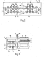
- the chambers 3 and 4 have the same structure. They differ only in the treatment temperature. It is therefore sufficient to describe the structure of chambers 3 and 4 using the example of chamber 4 shown in FIG. 2.
- the chamber 4 is divided by a central, horizontal partition 6 into an upper part chamber 4a and a lower part chamber 4b.
- the atmosphere of the chamber 4a is heated, for example by gas-powered burners 7.
- a fan 8 By means of a fan 8, it is possible to circulate the atmosphere through the subchambers 4a, 4b in the direction of the arrows P.
- a transport device which transports the tubes 9 in a translationally opposite manner to the direction of flow of the atmosphere through the partial chambers 4a, 4b.
- the transport device consists of one or more parallel endless chains 10a, 10b which are guided and driven via deflection rollers 11, 12.
- the chain 10a, 10b carries a plurality of spaced apart, driven rollers 13 which are equipped with a plurality of equally large circular disks 14 which are spaced apart.
- the circular disks 14 of adjacent rollers each carry a tube 9.
- the chains 10a, 10b could also carry driven cantilever arms which project axially into the tubes 9. In any case, the area supported by the support elements is small.
- the chamber 5 has a driven pair of rollers 15, which supports the tubes 9 and sets them in self-rotation.
- the tubes are heated by a ceiling heating element 16 and a heating element 17 projecting axially into the tubes 9.
- the chamber 5 can be lowered from an upper, excellent position in FIG. 3 into a lower, dashed position. Terminals 18a, 18b facing the outlet and inlet of the subchambers 4a, 4b are held on the chamber 5, with which the outlet and inlet of the subchambers 4a, 4b can alternately be closed depending on the position of the chamber 5.
- the inlet and outlet of the chamber 5 can be partitioned off by means of a slide plate 19.
- the heating device 15, 16 it is possible to heat the tubes during the self-rotation from the low starting temperature when they are taken over to the desired high sintering temperature. After this heating, the heating device can be switched off and the atmosphere of the chamber can be reduced to the temperature which corresponds to the temperature at the beginning of the downstream chamber 4b.
- the tubes are manufactured with the system described in the following manner:
- the hollow strands formed by the extruder 1 are cut to length in the cutting, shaping and aligning unit, brought to precise dimensions and aligned.
- the tubes 9 shaped in this way are transferred into the upper partial chamber of the chamber 3 by axial displacement.
- the transport device of this chamber supports the tubes on two pairs of circular disks and sets the tubes 9 in rotation.
- the partial transport also takes place during this rotation.
- the atmosphere of the / chamber is set to a drying temperature. In order not to suddenly expose the tubes to too high a temperature, the temperature rises during transport. For this purpose, the tubes are exposed to the outside of air flowing in counterflow. swept over.
- the control of the air to be blown into the interior of the tubes can be chosen accordingly.
- the tubes 9 are again axially displaced and transferred to the corresponding transport device of the downstream partial chamber 4a.
- the transport in this chamber is the same, as is the type of heating, but with higher temperatures.
- the tubes are again axially displaced into the chamber 5, where they are heated up to the sintering temperature. Since the initial temperature of the chamber 5 is equal to the temperature at the end of the chamber 4 a , the tubes are not burdened by a harmful temperature jump. The heating in the chamber 5 then takes place very quickly, which is harmless because of the uniform heating from the outside and inside with simultaneous rotation.
- the tubes After reaching the sintering temperature and then cooling down to the temperature prevailing at the beginning of the sub-chamber 4b, the tubes are again axially displaced and transferred to the lower strand 10a of the transport device in the sub-chamber 4b. Cooling takes place in this area, and continuously, because here too the tubes were swept with countercurrent cooling air. This cooling air comes from the upper part chamber 4a. In this way, heat exchange is obtained between the two subchambers 4a, 4b. In a corresponding manner, the tubes are cooled in the next cooling zone of chamber 3. At the end of chamber 3, the tubes are pushed axially out of the system.
- the tubes are supported on circular disks 5 or on cantilever arms, the outside and inside surfaces can not only be acted upon well by hot air or cooling air, but there is also enough space for shards to fall through if the tubes are very close to one another, be it that tubes of large diameter are transported, or that the support elements are close to each other.
Landscapes
- Engineering & Computer Science (AREA)
- Chemical & Material Sciences (AREA)
- Ceramic Engineering (AREA)
- Organic Chemistry (AREA)
- Materials Engineering (AREA)
- Mechanical Engineering (AREA)
- General Engineering & Computer Science (AREA)
- Structural Engineering (AREA)
- Manufacturing & Machinery (AREA)
- Dispersion Chemistry (AREA)
- Inorganic Chemistry (AREA)
- Physics & Mathematics (AREA)
- Thermal Sciences (AREA)
- Crystallography & Structural Chemistry (AREA)
- Metallurgy (AREA)
- Tunnel Furnaces (AREA)
- Muffle Furnaces And Rotary Kilns (AREA)
Priority Applications (1)
| Application Number | Priority Date | Filing Date | Title |
|---|---|---|---|
| AT84108379T ATE28510T1 (de) | 1983-07-19 | 1984-07-17 | Verfahren zur waermebehandlung von zylindrischen gegenstaenden, insbesondere roehren, insbesondere aus keramischem material, und durchlaufofen zur durchfuehrung des verfahrens. |
Applications Claiming Priority (2)
| Application Number | Priority Date | Filing Date | Title |
|---|---|---|---|
| DE3325944 | 1983-07-19 | ||
| DE3325944 | 1983-07-19 |
Publications (3)
| Publication Number | Publication Date |
|---|---|
| EP0131955A1 true EP0131955A1 (fr) | 1985-01-23 |
| EP0131955B1 EP0131955B1 (fr) | 1987-07-22 |
| EP0131955B2 EP0131955B2 (fr) | 1993-01-20 |
Family
ID=6204320
Family Applications (1)
| Application Number | Title | Priority Date | Filing Date |
|---|---|---|---|
| EP84108379A Expired - Lifetime EP0131955B2 (fr) | 1983-07-19 | 1984-07-17 | Procédé et installation pour le traitement thermique d'objets cylindriques, en particulier de tubes, notamment fait de matériaux céramiques |
Country Status (4)
| Country | Link |
|---|---|
| US (1) | US4628615A (fr) |
| EP (1) | EP0131955B2 (fr) |
| AT (1) | ATE28510T1 (fr) |
| DE (1) | DE3464960D1 (fr) |
Cited By (1)
| Publication number | Priority date | Publication date | Assignee | Title |
|---|---|---|---|---|
| WO1993016342A1 (fr) * | 1992-02-05 | 1993-08-19 | Hydraload Research And Development Limited | Processus thermique selon lequel la charge est tournee autour de l'axe longitudinal |
Families Citing this family (8)
| Publication number | Priority date | Publication date | Assignee | Title |
|---|---|---|---|---|
| GB8813814D0 (en) * | 1988-06-10 | 1988-07-13 | Naylor Bros Clayware Ltd | Conveyor mechanism |
| DE3832734C1 (fr) * | 1988-09-27 | 1990-03-29 | A.P.T. Anlagen Fuer Pyrotechnik Gmbh, 4000 Duesseldorf, De | |
| DE3915718C1 (fr) * | 1989-05-13 | 1990-09-20 | Schniering, Alfred, Dipl.-Ing., 4390 Gladbeck, De | |
| US5656220A (en) * | 1995-08-11 | 1997-08-12 | Mountain Safety Research | Method for the extrusion of ceramic filter media |
| US6277443B1 (en) * | 1998-06-30 | 2001-08-21 | John Maneely Company | Low lead or no lead batch galvanization process |
| EP3310723B1 (fr) | 2015-06-16 | 2021-05-26 | Becton Dickinson France | Systeme de transport pour le recuit de recipients en verre |
| US9914593B1 (en) * | 2016-11-08 | 2018-03-13 | Berry Global Films, Llc | System and method of rolling material in a conveyor environment |
| CN110186276A (zh) * | 2019-07-04 | 2019-08-30 | 烟台大学 | 一种用于提高回转形陶瓷构件烧成率的烧结炉及方法 |
Citations (6)
| Publication number | Priority date | Publication date | Assignee | Title |
|---|---|---|---|---|
| US2481130A (en) * | 1945-05-05 | 1949-09-06 | Eagle Picher Co | Drier for thermal pipe insulation |
| US2612706A (en) * | 1949-12-13 | 1952-10-07 | Pacific Clay Products | Continuous manufacture of extruded clay composition bodies |
| DE1268318B (de) * | 1961-04-14 | 1968-05-16 | Norton Co | Verfahren und Ofen zum Brennen keramischer Gegenstaende kreisfoermigen Querschnitts |
| FR2314117A1 (fr) * | 1975-06-10 | 1977-01-07 | Physique Appliquee Ind | Dispositif d'entrainement de pieces tubulaires, notamment dans des fours de traitement thermique |
| FR2325007A1 (fr) * | 1975-09-22 | 1977-04-15 | Saint Gobain | Procede et dispositif pour le traitement par des gaz d'elements traversant une enceinte |
| EP0005940A1 (fr) * | 1978-05-26 | 1979-12-12 | The Hepworth Iron Company Limited | Procédé, four et dispositif pour la cuisson de produits céramiques |
Family Cites Families (12)
| Publication number | Priority date | Publication date | Assignee | Title |
|---|---|---|---|---|
| US2762321A (en) * | 1952-10-14 | 1956-09-11 | Read Standard Corp | Baking oven |
| US2708796A (en) * | 1953-05-08 | 1955-05-24 | Frank D Adamy | Pipe holder and drier assembly |
| US3080157A (en) * | 1959-01-12 | 1963-03-05 | Dravo Corp | Sintering apparatus |
| US3111452A (en) * | 1961-02-09 | 1963-11-19 | Kyova Fiber Pipe Company | Method and apparatus for making fiber conduit |
| US3198501A (en) * | 1963-04-10 | 1965-08-03 | Banister Construction 1963 Ltd | Apparatus for heating tubular metal goods |
| US3430308A (en) * | 1966-08-25 | 1969-03-04 | Jerold H Van Alsburg | Materials handling and treating system |
| US3815881A (en) * | 1971-12-21 | 1974-06-11 | Riker Laboratories Inc | Tube annealing apparatus and method |
| NL165222C (nl) * | 1972-11-21 | 1981-03-16 | Prolizenz Ag | Werkwijze en inrichting voor warmtebehandeling van materiaal, zoals staven, blokken, buizen en dergelijke. |
| US4083119A (en) * | 1976-01-30 | 1978-04-11 | Pullman Incorporated, Pullman Swindell Division | Roller dryer for clay pipe |
| US4142304A (en) * | 1976-09-17 | 1979-03-06 | Saint-Gobain Industries | Apparatus for gas treatment of articles traversing an enclosure |
| US4195418A (en) * | 1978-09-18 | 1980-04-01 | Scm Corporation | Zoned heat treating apparatus |
| IT1100344B (it) * | 1978-11-23 | 1985-09-28 | Welko Ind Spa | Forno a rulli incorporante un canale di essiccazione,particolarmente per materiali ceramici o refrattari |
-
1984
- 1984-07-17 EP EP84108379A patent/EP0131955B2/fr not_active Expired - Lifetime
- 1984-07-17 AT AT84108379T patent/ATE28510T1/de not_active IP Right Cessation
- 1984-07-17 DE DE8484108379T patent/DE3464960D1/de not_active Expired
- 1984-07-19 US US06/632,450 patent/US4628615A/en not_active Expired - Fee Related
Patent Citations (6)
| Publication number | Priority date | Publication date | Assignee | Title |
|---|---|---|---|---|
| US2481130A (en) * | 1945-05-05 | 1949-09-06 | Eagle Picher Co | Drier for thermal pipe insulation |
| US2612706A (en) * | 1949-12-13 | 1952-10-07 | Pacific Clay Products | Continuous manufacture of extruded clay composition bodies |
| DE1268318B (de) * | 1961-04-14 | 1968-05-16 | Norton Co | Verfahren und Ofen zum Brennen keramischer Gegenstaende kreisfoermigen Querschnitts |
| FR2314117A1 (fr) * | 1975-06-10 | 1977-01-07 | Physique Appliquee Ind | Dispositif d'entrainement de pieces tubulaires, notamment dans des fours de traitement thermique |
| FR2325007A1 (fr) * | 1975-09-22 | 1977-04-15 | Saint Gobain | Procede et dispositif pour le traitement par des gaz d'elements traversant une enceinte |
| EP0005940A1 (fr) * | 1978-05-26 | 1979-12-12 | The Hepworth Iron Company Limited | Procédé, four et dispositif pour la cuisson de produits céramiques |
Cited By (1)
| Publication number | Priority date | Publication date | Assignee | Title |
|---|---|---|---|---|
| WO1993016342A1 (fr) * | 1992-02-05 | 1993-08-19 | Hydraload Research And Development Limited | Processus thermique selon lequel la charge est tournee autour de l'axe longitudinal |
Also Published As
| Publication number | Publication date |
|---|---|
| EP0131955B1 (fr) | 1987-07-22 |
| EP0131955B2 (fr) | 1993-01-20 |
| ATE28510T1 (de) | 1987-08-15 |
| DE3464960D1 (en) | 1987-08-27 |
| US4628615A (en) | 1986-12-16 |
Similar Documents
| Publication | Publication Date | Title |
|---|---|---|
| EP0336120A2 (fr) | Dispositif de traitement thermique et/ou de séchage d'une bande de matière en mouvement | |
| DE2254848A1 (de) | Verfahren zum thermischen nachverbrennen von abluft aus industriellen arbeitsanlagen und vorrichtung zur durchfuehrung dieses verfahrens | |
| DE2637646B2 (de) | Anwärmofen | |
| DE2947358C2 (de) | Rollenofen mit Brenntunnel | |
| EP0131955B1 (fr) | Procédé et installation pour le traitement thermique d'objets cylindriques, en particulier de tubes, notamment fait de matériaux céramiques | |
| EP0270043A2 (fr) | Procédé de traitement thermique, en particulier de produits céramiques plutôt plats, et four continu pour sa réalisation | |
| DE1596639C3 (de) | Vorrichtung zum Abstützen von Glasplatten. Ausscheidung aus: 1471948 | |
| WO1983002661A1 (fr) | Four de prechauffage de materiaux allonges | |
| EP0236666A2 (fr) | Procédé de réchauffage de produits semi-finis provenant d'installations de coulée continue ou d'installations de formage en vue de leur chargement dans des installations de formage ou de finissage | |
| DE2742320C3 (de) | Vorrichtung zum Kühlen von langgestreckten erwärmten Werkstücken | |
| DD149383A5 (de) | Verfahren und vorrichtung zum kontinuierlichen waermebehandeln von vereinzeltem,langgestrecktem metallischem gut | |
| EP0179050B1 (fr) | Four pour le traitement thermique de barres d'un métal léger | |
| EP0361147A1 (fr) | Four continu pour le traitement thermique d'articles, en particulier de tubes céramiques | |
| AT509356B1 (de) | Vorrichtung und verfahren zum wärmebehandeln von stahldrähten | |
| DE3783383T2 (de) | Verfahren zur kuehlung von gebrannten produkten in einem ofen. | |
| EP0093877B1 (fr) | Dispositif pour le traitement thermique de pièces de matière à haute température | |
| DE19538364C2 (de) | Vorrichtung zur Schnellerwärmung von Metall-Preßbolzen | |
| DE887102C (de) | Vorrichtung zur maschinellen Waermebehandlung von Glasroehren | |
| AT390322B (de) | Vorrichtung zum durchwaermen von stahlteilen | |
| DE102005045051A1 (de) | Drehrohrofen | |
| DE1558559C3 (de) | Heißgas Konvektions Ofen | |
| DE2219715C3 (de) | Band-Schwebeführungsvorrichtung zur Wärmebehandlung innerhalb eines Ofens | |
| DE945513C (de) | Gasbefeuerter Schweissofen fuer einen ununterbrochenen Durchsatz von Roehrenstreifenbei der Herstellung von Schweissrohren, insbesondere Gasrohren | |
| DE4400542C2 (de) | Verfahren zur Erhöhung der Festigkeit von Glaskörpern und Vorrichtung hierfür | |
| DE4130126C2 (de) | Tunnelofen in der Ziegelindustrie |
Legal Events
| Date | Code | Title | Description |
|---|---|---|---|
| PUAI | Public reference made under article 153(3) epc to a published international application that has entered the european phase |
Free format text: ORIGINAL CODE: 0009012 |
|
| AK | Designated contracting states |
Designated state(s): AT BE CH DE FR GB IT LI LU NL SE |
|
| 17P | Request for examination filed |
Effective date: 19850309 |
|
| 17Q | First examination report despatched |
Effective date: 19860217 |
|
| RAP1 | Party data changed (applicant data changed or rights of an application transferred) |
Owner name: A.P.T. ANLAGEN FUER PYROTECHNIK GMBH |
|
| ITF | It: translation for a ep patent filed | ||
| GRAA | (expected) grant |
Free format text: ORIGINAL CODE: 0009210 |
|
| AK | Designated contracting states |
Kind code of ref document: B1 Designated state(s): AT BE CH DE FR GB IT LI LU NL SE |
|
| REF | Corresponds to: |
Ref document number: 28510 Country of ref document: AT Date of ref document: 19870815 Kind code of ref document: T |
|
| REF | Corresponds to: |
Ref document number: 3464960 Country of ref document: DE Date of ref document: 19870827 |
|
| ET | Fr: translation filed | ||
| PLBI | Opposition filed |
Free format text: ORIGINAL CODE: 0009260 |
|
| 26 | Opposition filed |
Opponent name: SCHNIERING, ALFRED, DIPL.-ING. Effective date: 19880415 |
|
| NLR1 | Nl: opposition has been filed with the epo |
Opponent name: ALFRED SCHNIERING. |
|
| ITTA | It: last paid annual fee | ||
| PUAH | Patent maintained in amended form |
Free format text: ORIGINAL CODE: 0009272 |
|
| STAA | Information on the status of an ep patent application or granted ep patent |
Free format text: STATUS: PATENT MAINTAINED AS AMENDED |
|
| 27A | Patent maintained in amended form |
Effective date: 19930120 |
|
| AK | Designated contracting states |
Kind code of ref document: B2 Designated state(s): AT BE CH DE FR GB IT LI LU NL SE |
|
| ITF | It: translation for a ep patent filed | ||
| REG | Reference to a national code |
Ref country code: CH Ref legal event code: AEN |
|
| ET3 | Fr: translation filed ** decision concerning opposition | ||
| NLR2 | Nl: decision of opposition | ||
| NLR3 | Nl: receipt of modified translations in the netherlands language after an opposition procedure | ||
| PGFP | Annual fee paid to national office [announced via postgrant information from national office to epo] |
Ref country code: CH Payment date: 19930625 Year of fee payment: 10 |
|
| PGFP | Annual fee paid to national office [announced via postgrant information from national office to epo] |
Ref country code: SE Payment date: 19930629 Year of fee payment: 10 |
|
| PGFP | Annual fee paid to national office [announced via postgrant information from national office to epo] |
Ref country code: LU Payment date: 19930701 Year of fee payment: 10 |
|
| EPTA | Lu: last paid annual fee | ||
| PG25 | Lapsed in a contracting state [announced via postgrant information from national office to epo] |
Ref country code: LU Free format text: LAPSE BECAUSE OF NON-PAYMENT OF DUE FEES Effective date: 19940717 |
|
| PG25 | Lapsed in a contracting state [announced via postgrant information from national office to epo] |
Ref country code: SE Effective date: 19940718 |
|
| PG25 | Lapsed in a contracting state [announced via postgrant information from national office to epo] |
Ref country code: LI Effective date: 19940731 Ref country code: CH Effective date: 19940731 |
|
| EUG | Se: european patent has lapsed |
Ref document number: 84108379.3 Effective date: 19950210 |
|
| REG | Reference to a national code |
Ref country code: CH Ref legal event code: PL |
|
| EUG | Se: european patent has lapsed |
Ref document number: 84108379.3 |
|
| PGFP | Annual fee paid to national office [announced via postgrant information from national office to epo] |
Ref country code: FR Payment date: 19950623 Year of fee payment: 12 |
|
| PGFP | Annual fee paid to national office [announced via postgrant information from national office to epo] |
Ref country code: GB Payment date: 19950727 Year of fee payment: 12 |
|
| PGFP | Annual fee paid to national office [announced via postgrant information from national office to epo] |
Ref country code: BE Payment date: 19950728 Year of fee payment: 12 |
|
| PGFP | Annual fee paid to national office [announced via postgrant information from national office to epo] |
Ref country code: NL Payment date: 19950731 Year of fee payment: 12 |
|
| PGFP | Annual fee paid to national office [announced via postgrant information from national office to epo] |
Ref country code: AT Payment date: 19950821 Year of fee payment: 12 |
|
| PGFP | Annual fee paid to national office [announced via postgrant information from national office to epo] |
Ref country code: DE Payment date: 19950822 Year of fee payment: 12 |
|
| PG25 | Lapsed in a contracting state [announced via postgrant information from national office to epo] |
Ref country code: GB Effective date: 19960717 Ref country code: AT Effective date: 19960717 |
|
| PG25 | Lapsed in a contracting state [announced via postgrant information from national office to epo] |
Ref country code: BE Effective date: 19960731 |
|
| APAC | Appeal dossier modified |
Free format text: ORIGINAL CODE: EPIDOS NOAPO |
|
| APAC | Appeal dossier modified |
Free format text: ORIGINAL CODE: EPIDOS NOAPO |
|
| BERE | Be: lapsed |
Owner name: A.P.T. ANLAGEN FUR PYROTECHNIK G.M.B.H. Effective date: 19960731 |
|
| PG25 | Lapsed in a contracting state [announced via postgrant information from national office to epo] |
Ref country code: NL Effective date: 19970201 |
|
| GBPC | Gb: european patent ceased through non-payment of renewal fee |
Effective date: 19960717 |
|
| PG25 | Lapsed in a contracting state [announced via postgrant information from national office to epo] |
Ref country code: FR Effective date: 19970328 |
|
| NLV4 | Nl: lapsed or anulled due to non-payment of the annual fee |
Effective date: 19970201 |
|
| PG25 | Lapsed in a contracting state [announced via postgrant information from national office to epo] |
Ref country code: DE Effective date: 19970501 |
|
| REG | Reference to a national code |
Ref country code: FR Ref legal event code: ST |
|
| APAH | Appeal reference modified |
Free format text: ORIGINAL CODE: EPIDOSCREFNO |