EP0131812B1 - Lese- und Entwertungsgerät für im voraus bezahlbare Karten, insbesondere zum Gebrauch von mit magnetischen Karten bedienbaren öffentlichen Telefonapparaten - Google Patents
Lese- und Entwertungsgerät für im voraus bezahlbare Karten, insbesondere zum Gebrauch von mit magnetischen Karten bedienbaren öffentlichen Telefonapparaten Download PDFInfo
- Publication number
- EP0131812B1 EP0131812B1 EP84107478A EP84107478A EP0131812B1 EP 0131812 B1 EP0131812 B1 EP 0131812B1 EP 84107478 A EP84107478 A EP 84107478A EP 84107478 A EP84107478 A EP 84107478A EP 0131812 B1 EP0131812 B1 EP 0131812B1
- Authority
- EP
- European Patent Office
- Prior art keywords
- card
- readout
- drum
- belt
- erase
- Prior art date
- Legal status (The legal status is an assumption and is not a legal conclusion. Google has not performed a legal analysis and makes no representation as to the accuracy of the status listed.)
- Expired
Links
Images

Classifications
-
- H—ELECTRICITY
- H04—ELECTRIC COMMUNICATION TECHNIQUE
- H04M—TELEPHONIC COMMUNICATION
- H04M17/00—Prepayment of wireline communication systems, wireless communication systems or telephone systems
- H04M17/02—Coin-freed or check-freed systems, e.g. mobile- or card-operated phones, public telephones or booths
- H04M17/026—Constructional features
-
- G—PHYSICS
- G06—COMPUTING OR CALCULATING; COUNTING
- G06K—GRAPHICAL DATA READING; PRESENTATION OF DATA; RECORD CARRIERS; HANDLING RECORD CARRIERS
- G06K13/00—Conveying record carriers from one station to another, e.g. from stack to punching mechanism
- G06K13/02—Conveying record carriers from one station to another, e.g. from stack to punching mechanism the record carrier having longitudinal dimension comparable with transverse dimension, e.g. punched card
- G06K13/07—Transporting of cards between stations
- G06K13/073—Transporting of cards between stations with continuous movement
-
- G—PHYSICS
- G06—COMPUTING OR CALCULATING; COUNTING
- G06Q—INFORMATION AND COMMUNICATION TECHNOLOGY [ICT] SPECIALLY ADAPTED FOR ADMINISTRATIVE, COMMERCIAL, FINANCIAL, MANAGERIAL OR SUPERVISORY PURPOSES; SYSTEMS OR METHODS SPECIALLY ADAPTED FOR ADMINISTRATIVE, COMMERCIAL, FINANCIAL, MANAGERIAL OR SUPERVISORY PURPOSES, NOT OTHERWISE PROVIDED FOR
- G06Q20/00—Payment architectures, schemes or protocols
- G06Q20/30—Payment architectures, schemes or protocols characterised by the use of specific devices or networks
- G06Q20/34—Payment architectures, schemes or protocols characterised by the use of specific devices or networks using cards, e.g. integrated circuit [IC] cards or magnetic cards
- G06Q20/343—Cards including a counter
- G06Q20/3433—Cards including a counter the counter having monetary units
-
- G—PHYSICS
- G07—CHECKING-DEVICES
- G07F—COIN-FREED OR LIKE APPARATUS
- G07F17/00—Coin-freed apparatus for hiring articles; Coin-freed facilities or services
- G07F17/0014—Coin-freed apparatus for hiring articles; Coin-freed facilities or services for vending, access and use of specific services not covered anywhere else in G07F17/00
-
- G—PHYSICS
- G07—CHECKING-DEVICES
- G07F—COIN-FREED OR LIKE APPARATUS
- G07F7/00—Mechanisms actuated by objects other than coins to free or to actuate vending, hiring, coin or paper currency dispensing or refunding apparatus
- G07F7/02—Mechanisms actuated by objects other than coins to free or to actuate vending, hiring, coin or paper currency dispensing or refunding apparatus by keys or other credit registering devices
Definitions
- This invention relates to a value-rated card readout and obliterating device, particularly for use with public telephone set enabling magnetic cards, as defined in the preamble of claim 1.
- a device of the type defined in the preamble of claim 1 is known from FR-A-2 382 720.
- US-A-4 262 312 describes a device for magnetic recording and printing of card mediums, thus not specifically designed for value-rated card readout and obliteration, including a freely rotatable drum for supporting and transferring a card from an inlet mouth to an outlet mouth, said inlet and outlet mouths being separated from each other, at least one endless drive belt in contact engagement with the drum surface, means for feeding a card in the nip between said belt and drum surface, thereby said card is transferred by said drive belt co-acting with the drum rotation, and belt deflecting means comprising a roller, the readout and erase magnetic head (together with a printing station) being arranged radially to said drum.
- the device of this invention essentially includes mechanical members for card entrainment and magnetic readout and cancel heads for reading and cancelling the magnetic traces, and -- where applied to telephone sets as contemplated by this invention -- an electronics for processing the readout data and an interface of connection to the set to be enabled.
- the task of this invention is to provide a simplified construction card readout and obliterating device, in particular one including mechanical card entrainment means, which can afford maximum reliability in operation for a minimal power requirement.
- the accomplishment of this task is obviously particularly important to the operation of public telephone sets both on account of the far-apart and capillary location of the sets, and to also ensure the availability of the service in the event of power outages by utilizing local power storage means which may be mere capacitors.
- a value-rated card readout and obliteration device particularly for use with public telephone set enabling magnetic cards, as defined in claim 1-
- the drive belt cooperates preferably with a second, driven belt receiving its motion from the drum; the two side-by-side belts act on the drum edges and correspondingly engage with the card edges to hold it correctly aligned during the transfer step.
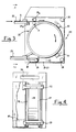
- a public telephone set of the conventional token and coin actuated type and at 20 the card readout and obliterating device according to the invention.
- This device comprises an enclosing case 21 having two front mouths 22-23, respectively for introducing and returning the cards, as well as a display 24 showing the credit figure.
- the introduction mouth 22 is provided with a mechanical feeler (not shown) adapted to detect a bevel s in the card S ( Figure 2) in order to prevent wrong introduction of the card which must have its magnetic track P facing up.
- Housed for free rotation within the enclosing case 21 is a card supporting and entraining drum 25. That drum, which is advantageously formed from a polymeric material, has a lightened construction, e.g. of the spoke type, and a width only slightly greater than that of the card S, and a diameter equal to about twice the maximum dimension of the card.
- first and second parallel belts 26-27 which engage with the drum surface over an arc length equal to one half its circumference; the belts being endless ones and each trained around pairs of lower and upper rollers 28-29, respectively.
- One of said belts e.g. the belt 26, is a driving belt and will be referred to as drive belt hereinafter.
- one roller in the lower pair 28 is a drive roller and derives its motion from a DC gear motor 30.
- the mouths 22-23 are located on the extensions of respective diametrically opposed tangent lines to the drum, and the outer rollers 29a in the upper pair, also tangent to said extensions, cooperate with a pinch roller 31 to form an initial card drive unit.
- the second, non-driving, belt is in turn driven by contact engagement with the drum, and this in order to prevent rotation of the card owing to any speed differentials of the belts.
- a magnetic reed switch 22a for consent to starting the gear motor 30.
- the card as introduced through the mouth 22, causes, therefore, the gear motor to be started together with the drum 25, and on being urged to contact the initial drive unit, is caught by the latter and fed into the nip between the drum outer surface and belts 26-27.
- the card will move together with the drum and be successively brought into alignment with first and second magnetic heads, respectively a readout one 32 and erase one 33.
- the heads are oriented radially to the drum 25 and spaced apart at an angular pitch of any selected length. It is advantageous that that length be selected to be at least equal to the card size and preferably slightly larger than said size.
- the card can be allowed to stay between the two heads, e.g. for the time lapse required for processing (including credit down counting) the data read by the head 32, which is followed by the obliteration command supplied to the head 33.
- the stay of a spent card S1 in between the heads allows sequential introduction of a further card S2 and, by selecting a suitably short time for readout, it becomes possible to prevent transfer of any left-over credit from a previously obliterated card to a next one.
- the stop and forward command past the stay position is supplied by a logics associated with the readout head; in the instance of a telephone application, forward movement is produced, for example, by the cash command from the exchange at the call end, or by a similar command from the exchange at the end of the credit element downcount.
- the card is caused to move past the intermediate stay zone and brought into alignment with the erase head, which partly or fully obliterates the credit elements recorded on the card magnetic trace.
- the card is ejected from the return mouth 23, also located on the extension of the tangent line to the drum 25.
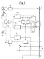
- FIG. 7 Shown in Figure 7 is a circuit diagram appropriate for the public telephone set shown in Figure 1.
- I designates the telephone set connection interface which controls the exchanged signals, which may be summarized as follows:
- Indicated at SS is an automatic switching selector which, on resetting, enables the heads 32 or 33 successively and selectively.
- the magnetic switch 22a Shown in the diagram is the magnetic switch 22a wherewith a flip-flop B1 is associated which serves presence detector functions.
- the other blocks have the following functions: DC1 key discriminator; DC2 unit and protection discriminator; R, first "1" recognition; CK, key counter; ST, readout head selector; Ls, write (obliteration) logics; CS, write circuit.
- the device operates as follows: on lifting the handset, if a card is present at the introduction mouth, the motor forward command is generated. The data read out by the readout head are transferred to the telephone set circuits, thereafter the motor forward movement is stopped and the card is positioned on the drum between the readout and obliteration stations.
- the readout data (including, for example, the card serial number NS, a key number NC, and the yet available telephone credit) are transferred to the exchange circuits for appropriate checking.
- the user receives the exchange tone and can begin to dial the desired telephone number; simultaneously on the device display there appears the amount of the usable credit.
- the automatic increments or trips sensed during the call are received by the set, which updates the left-over credit displaying it.
- an acoustical warning tone is supplied and the left-over displayed credit is pulsed.
- card return is commanded. Then, the motor forward control is reactivated which causes the card to move past the obliteration station. The card is updated with the left-over credit and returned to the user through the return mouth.
- the user If on approaching exhaustion of the credit, during a call, the user inserts a fresh card through the inlet mouth, simultaneously with full obliteration and ejection of the previous card, the card thus presented is readout and the user allowed to carry on the conversation.
Landscapes
- Engineering & Computer Science (AREA)
- Physics & Mathematics (AREA)
- General Physics & Mathematics (AREA)
- Theoretical Computer Science (AREA)
- Computer Networks & Wireless Communication (AREA)
- Business, Economics & Management (AREA)
- Signal Processing (AREA)
- Microelectronics & Electronic Packaging (AREA)
- Computer Security & Cryptography (AREA)
- Accounting & Taxation (AREA)
- Strategic Management (AREA)
- General Business, Economics & Management (AREA)
- Prepayment Telephone Systems (AREA)
- Credit Cards Or The Like (AREA)
- Control Of Vending Devices And Auxiliary Devices For Vending Devices (AREA)
Claims (7)
- Lese- und Entwertegerät für im voraus bezahlte Magnetkarten, enthaltend mechanische Kartenmitnahmemittel (25 - 30) und getrennte Magnetspuren-Lese- und -Löschmittel (32, 33), insbesondere zur Verwendung mit Magnetkarten (S) für öffentliche Telefone, dadurch gekennzeichnet, daß die Kartenmitnahmemittel enthalten:- eine frei drehbare Trommel (25) zur Übertragung der Karte (S) von einer Einlaßöffnung (22) zu einer Auslaßöffnung (23), wobei Einlaßöffnung und Auslaßöffnung voneinander getrennt sind,- einen endlosen Riemenantrieb (26) in Berührungseingriff mit der Trommeloberfläche, wobei der endlose Riemen von Riemenablenkmitteln (28, 29) mit mindestens einer Antriebswalze (28) angetrieben wird und die Ablenkmittel derart angeordnet sind, daß sie einen Spalt zum Einziehen der Karte zwischen den endlosen Riemen (26) und die Trommel (25) bilden, und- Mittel (31) zum Zuführen der Karte in den Schlitz, derart daß die Karte von dem mit der Trommeldrehung zusammenwirkenden endlosen Riemenantrieb transportiert wird,und daß die Magnet-Lese- und Löschmittel einen Spurenauslesekopf (32) und einen Spurenlöschkopf (33) enthalten, wobei der winkelmäßige Abstand zwischen dem Lesekopf und dem Löschkopf derart ausgewählt ist, daß er mindestens der Abmessung der Karte in der Transportrichtung gleich ist, und daß Motormittel (30) und Steuermittel (I, B1, 22a) vorgesehen sind, um die Karte von dem Schlitz zu transportieren und sie in der Lücke zwischen dem Lesekopf und dem Löschkopf für das Zeitintervall anzuhalten, das für den nach dem Leseprozeß durchzuführenden Löschprozeß erforderlich ist.
- Gerät nach Anspruch 1, dadurch gekennzeichnet, daß es einen zweiten mit dem Antriebsriemen (26) zusammenwirkenden und seine Bewegung von der Trommel (25) erhaltenden angetriebenen Riemen (27) aufweist, und daß die beiden einander flankierenden Riemen (26, 27) auf die Trommelkanten einwirken und dementsprechend an den Kanten der Karte (S) angreifen, um sie während der Bewegung korrekt ausgerichtet zu halten.
- Gerät nach Anspruch 2, dadurch gekennzeichnet, daß der angetriebene und der Antriebsriemen (26, 27) die Trommel (25) über einen Bogen einschließen, der in seiner Länge ihrem halben Umfang gleich ist, und daß die Karteneinlaß- und Auslaßöffnungen (22, 23) in Verlängerung der Tangenten an die Trommel (25) angeordnet sind, die von den Enden des den Bogen begrenzenden Durchmessers ausgehen.
- Gerät nach Anspruch 3, dadurch gekennzeichnet, daß die Kartenzuführmittel zum Einführen einer Karte in den Spalt zwischen dem angetriebenen Riemen und dem Antriebsriemen (26, 27) und der Trommeloberfläche eine Klemmwalze aufweisen, die mit ein Paar von Riemenablenkrollen zusammenwirken.
- Gerät nach Anspruch 4, dadurch gekennzeichnet, daß es an der Karteneinführöffnung (22) einen Magnetschalter (22a) aufweist, der den Motor (30) mit Hilfe eines Flip-Flops (B1) und einer Schnittstelle (I) bei Vorhandensein der Karte (S) einschaltet.
- Gerät nach Anspruch 5, dadurch gekennzeichnet, daß jeder Kopf (32, 33) durch einen automatischen Umschaltselektor, der die Köpfe sequentiell einschaltet, mit einer jeweiligen (Lese- bzw. Lösch-) Antriebsschaltung verbunden ist.
- Gerät nach Anspruch 5, dadurch gekennzeichnet, daß es elektronische Schaltungsmittel (DC1, DC2, ST, LS) mit einer Schnittstelle (I ) zur Verbindung mit einem einzuschaltenden Satz aufweist, wobei die Schnittstelle die wechselseitig ausgestauschten Signale zwischen dem Gerät und dem Satz überprüft, enthaltend: Kartenanwesenheitssignal (a) -Antriebsmotorvorwärtskommando (b) -Auslesedatenübertragung (c) -Löschkommando (d).
Applications Claiming Priority (2)
| Application Number | Priority Date | Filing Date | Title |
|---|---|---|---|
| IT67770/83A IT1162910B (it) | 1983-07-15 | 1983-07-15 | Dispositivo di lettura e obliterazione di schede valorizzate particolarmente schede magnetiche per l'abilitazione di apparecchi telefonici pubblici |
| IT6777083 | 1983-07-15 |
Publications (3)
| Publication Number | Publication Date |
|---|---|
| EP0131812A2 EP0131812A2 (de) | 1985-01-23 |
| EP0131812A3 EP0131812A3 (en) | 1988-01-13 |
| EP0131812B1 true EP0131812B1 (de) | 1991-10-23 |
Family
ID=11305160
Family Applications (1)
| Application Number | Title | Priority Date | Filing Date |
|---|---|---|---|
| EP84107478A Expired EP0131812B1 (de) | 1983-07-15 | 1984-06-28 | Lese- und Entwertungsgerät für im voraus bezahlbare Karten, insbesondere zum Gebrauch von mit magnetischen Karten bedienbaren öffentlichen Telefonapparaten |
Country Status (3)
| Country | Link |
|---|---|
| EP (1) | EP0131812B1 (de) |
| DE (1) | DE3485196D1 (de) |
| IT (1) | IT1162910B (de) |
Families Citing this family (7)
| Publication number | Priority date | Publication date | Assignee | Title |
|---|---|---|---|---|
| GB2211376B (en) * | 1987-10-19 | 1991-07-10 | Mars Inc | Telephone set |
| US5175423A (en) * | 1991-05-09 | 1992-12-29 | Verifone, Inc. | Rotary data card scanning apparatus |
| US5221831A (en) * | 1991-11-29 | 1993-06-22 | Indala Corporation | Flap-type portal reader |
| US5662201A (en) * | 1992-04-16 | 1997-09-02 | Mars Incorporated | Banknote reader |
| EP0883093B1 (de) * | 1992-04-16 | 2005-11-02 | Mars, Incorporated | Banknotenleser |
| US5735516A (en) * | 1992-05-27 | 1998-04-07 | Mars Incorporated | Apparatus for handling sheets |
| FR2777099A1 (fr) * | 1998-04-01 | 1999-10-08 | Hubert Calvados | Support portant des moyens de codage permettant son authentification ainsi que dispositif de relecture d'un tel support |
Family Cites Families (5)
| Publication number | Priority date | Publication date | Assignee | Title |
|---|---|---|---|---|
| US3641931A (en) * | 1970-03-31 | 1972-02-15 | Ibm | Analyzing, orienting and printing means in ticket handling mechanism |
| US4071741A (en) * | 1976-03-26 | 1978-01-31 | Umc Industries, Inc. | Card validator |
| NL7607250A (nl) * | 1976-06-30 | 1978-01-03 | Ibm Nederland | Documentenverwerkingsinrichting. |
| IT1073286B (it) * | 1977-03-04 | 1985-04-13 | Rossi Mario | Dispositivo per il riconoscimento ed il progressivo annulamento di informazioni registrate su un supporto magnetico |
| US4262312A (en) * | 1978-03-15 | 1981-04-14 | Matsushita Communication Industrial Co., Ltd. | Magnetic recording and printing device for card mediums |
-
1983
- 1983-07-15 IT IT67770/83A patent/IT1162910B/it active
-
1984
- 1984-06-28 EP EP84107478A patent/EP0131812B1/de not_active Expired
- 1984-06-28 DE DE8484107478T patent/DE3485196D1/de not_active Expired - Fee Related
Also Published As
| Publication number | Publication date |
|---|---|
| IT8367770A0 (it) | 1983-07-15 |
| DE3485196D1 (de) | 1991-11-28 |
| EP0131812A2 (de) | 1985-01-23 |
| EP0131812A3 (en) | 1988-01-13 |
| IT1162910B (it) | 1987-04-01 |
Similar Documents
| Publication | Publication Date | Title |
|---|---|---|
| US3611293A (en) | Access-control equipment and item-dispensing systems including such equipment | |
| US3937925A (en) | Modular transaction terminal with microprocessor control | |
| US3023851A (en) | Electronic marketing system and apparatus | |
| US3629834A (en) | Access-control equipment and item-dispensing systems controlled by credit card | |
| US3039582A (en) | Subscriber controlled apparatus | |
| US3696335A (en) | Credit verification system | |
| US4540106A (en) | Bag processing unit of an automatic transaction machine | |
| US3641497A (en) | Access-control equipment and item-dispensing systems including such equipment | |
| GB2119993A (en) | Automatic transaction machine | |
| EP0131812B1 (de) | Lese- und Entwertungsgerät für im voraus bezahlbare Karten, insbesondere zum Gebrauch von mit magnetischen Karten bedienbaren öffentlichen Telefonapparaten | |
| JPH0648838B2 (ja) | 公衆電話機 | |
| US3818446A (en) | Magnetic ink character transition reader | |
| US5225665A (en) | Ticket originating and processing device for transit vehicle | |
| US5424523A (en) | Record medium and record medium processing apparatus | |
| US3735095A (en) | Card routing apparatus | |
| GB2114346A (en) | Apparatus for issuing bond, ticket, certificate or the like | |
| JPS60123981A (ja) | カ−ド処理装置 | |
| JPH0260035B2 (de) | ||
| JPH0248784A (ja) | カード処理装置 | |
| JPS6120187A (ja) | 払戻し機能付き券売機 | |
| JP2899509B2 (ja) | カード待避機構 | |
| JP2824323B2 (ja) | 有料道路通行券の情報読取方法 | |
| GB2129593A (en) | Automatic teller machine | |
| JP3042265B2 (ja) | 磁気カード及び磁気カード判定装置 | |
| JP2909073B2 (ja) | 券類発行装置 |
Legal Events
| Date | Code | Title | Description |
|---|---|---|---|
| PUAI | Public reference made under article 153(3) epc to a published international application that has entered the european phase |
Free format text: ORIGINAL CODE: 0009012 |
|
| AK | Designated contracting states |
Designated state(s): BE CH DE FR GB LI |
|
| PUAL | Search report despatched |
Free format text: ORIGINAL CODE: 0009013 |
|
| AK | Designated contracting states |
Kind code of ref document: A3 Designated state(s): BE CH DE FR GB LI |
|
| 17P | Request for examination filed |
Effective date: 19880629 |
|
| 17Q | First examination report despatched |
Effective date: 19890919 |
|
| GRAA | (expected) grant |
Free format text: ORIGINAL CODE: 0009210 |
|
| AK | Designated contracting states |
Kind code of ref document: B1 Designated state(s): BE CH DE FR GB LI |
|
| REF | Corresponds to: |
Ref document number: 3485196 Country of ref document: DE Date of ref document: 19911128 |
|
| ET | Fr: translation filed | ||
| PGFP | Annual fee paid to national office [announced via postgrant information from national office to epo] |
Ref country code: FR Payment date: 19920615 Year of fee payment: 9 |
|
| PGFP | Annual fee paid to national office [announced via postgrant information from national office to epo] |
Ref country code: CH Payment date: 19920617 Year of fee payment: 9 Ref country code: BE Payment date: 19920617 Year of fee payment: 9 |
|
| PGFP | Annual fee paid to national office [announced via postgrant information from national office to epo] |
Ref country code: GB Payment date: 19920618 Year of fee payment: 9 |
|
| PGFP | Annual fee paid to national office [announced via postgrant information from national office to epo] |
Ref country code: DE Payment date: 19920623 Year of fee payment: 9 |
|
| PLBE | No opposition filed within time limit |
Free format text: ORIGINAL CODE: 0009261 |
|
| STAA | Information on the status of an ep patent application or granted ep patent |
Free format text: STATUS: NO OPPOSITION FILED WITHIN TIME LIMIT |
|
| 26N | No opposition filed | ||
| PG25 | Lapsed in a contracting state [announced via postgrant information from national office to epo] |
Ref country code: GB Effective date: 19930628 |
|
| PG25 | Lapsed in a contracting state [announced via postgrant information from national office to epo] |
Ref country code: LI Effective date: 19930630 Ref country code: CH Effective date: 19930630 Ref country code: BE Effective date: 19930630 |
|
| BERE | Be: lapsed |
Owner name: URMET S.P.A. COSTRUZIONI ELETTRO-TELEFONICHE Effective date: 19930630 |
|
| GBPC | Gb: european patent ceased through non-payment of renewal fee |
Effective date: 19930628 |
|
| PG25 | Lapsed in a contracting state [announced via postgrant information from national office to epo] |
Ref country code: FR Effective date: 19940228 |
|
| REG | Reference to a national code |
Ref country code: CH Ref legal event code: PL |
|
| PG25 | Lapsed in a contracting state [announced via postgrant information from national office to epo] |
Ref country code: DE Effective date: 19940301 |
|
| REG | Reference to a national code |
Ref country code: FR Ref legal event code: ST |