EP0131082B1 - Device for placing pallets on a loading area - Google Patents
Device for placing pallets on a loading area Download PDFInfo
- Publication number
- EP0131082B1 EP0131082B1 EP83810308A EP83810308A EP0131082B1 EP 0131082 B1 EP0131082 B1 EP 0131082B1 EP 83810308 A EP83810308 A EP 83810308A EP 83810308 A EP83810308 A EP 83810308A EP 0131082 B1 EP0131082 B1 EP 0131082B1
- Authority
- EP
- European Patent Office
- Prior art keywords
- pallet
- receptacle
- conveyor
- driving means
- arm
- Prior art date
- Legal status (The legal status is an assumption and is not a legal conclusion. Google has not performed a legal analysis and makes no representation as to the accuracy of the status listed.)
- Expired
Links
Images


Classifications
-
- B—PERFORMING OPERATIONS; TRANSPORTING
- B65—CONVEYING; PACKING; STORING; HANDLING THIN OR FILAMENTARY MATERIAL
- B65G—TRANSPORT OR STORAGE DEVICES, e.g. CONVEYORS FOR LOADING OR TIPPING, SHOP CONVEYOR SYSTEMS OR PNEUMATIC TUBE CONVEYORS
- B65G65/00—Loading or unloading
-
- B—PERFORMING OPERATIONS; TRANSPORTING
- B65—CONVEYING; PACKING; STORING; HANDLING THIN OR FILAMENTARY MATERIAL
- B65G—TRANSPORT OR STORAGE DEVICES, e.g. CONVEYORS FOR LOADING OR TIPPING, SHOP CONVEYOR SYSTEMS OR PNEUMATIC TUBE CONVEYORS
- B65G57/00—Stacking of articles
-
- B—PERFORMING OPERATIONS; TRANSPORTING
- B65—CONVEYING; PACKING; STORING; HANDLING THIN OR FILAMENTARY MATERIAL
- B65G—TRANSPORT OR STORAGE DEVICES, e.g. CONVEYORS FOR LOADING OR TIPPING, SHOP CONVEYOR SYSTEMS OR PNEUMATIC TUBE CONVEYORS
- B65G7/00—Devices for assisting manual moving or tilting heavy loads
- B65G7/02—Devices adapted to be interposed between loads and the ground or floor, e.g. crowbars with means for assisting conveyance of loads
- B65G7/08—Devices adapted to be interposed between loads and the ground or floor, e.g. crowbars with means for assisting conveyance of loads for tilting the loads
-
- Y—GENERAL TAGGING OF NEW TECHNOLOGICAL DEVELOPMENTS; GENERAL TAGGING OF CROSS-SECTIONAL TECHNOLOGIES SPANNING OVER SEVERAL SECTIONS OF THE IPC; TECHNICAL SUBJECTS COVERED BY FORMER USPC CROSS-REFERENCE ART COLLECTIONS [XRACs] AND DIGESTS
- Y10—TECHNICAL SUBJECTS COVERED BY FORMER USPC
- Y10S—TECHNICAL SUBJECTS COVERED BY FORMER USPC CROSS-REFERENCE ART COLLECTIONS [XRACs] AND DIGESTS
- Y10S414/00—Material or article handling
- Y10S414/10—Associated with forming or dispersing groups of intersupporting articles, e.g. stacking patterns
- Y10S414/106—Associated with forming or dispersing groups of intersupporting articles, e.g. stacking patterns including means for supplying pallet or separator to group
Definitions
- the subject of the present invention is a device for placing pallets on a loading area, comprising a mobile conveyor, provided with motor means capable of imposing on it a horizontal displacement of positioning between a withdrawal position and a loading position, in driving with it in this displacement an empty pallet and further comprising an openwork receptacle, the conveyor being arranged so as to release a pallet from the receptacle during said positioning movement.
- a device of this kind is already known, in particular from the patent application specification FR-2 207 076.
- the conveyor is capable of moving one by one the pallets stacked in a receptacle which constitutes a store and of advancing them on a table. load located above the ground, at the base of the stack of pallets in the store.
- the present invention results from the search for compact, simple, automatic means capable of being associated with the handling device of the aforementioned European request, and allowing the placing of the pallets in a change position determined precisely, and their evacuation after loading in a systematic and rapid manner.
- the device according to the present invention can be associated with various automatic installations for distributing and transporting objects. It can also be combined with fully manual loading operations.
- the pallet placement device of the kind mentioned at the beginning is characterized in that the receptacle is capable of tilting around a horizontal axis between a receiving position and a folding position, and of supporting in the position receiving the pallet placed on its edge, and in that the transporter is arranged so as to engage in the pallet disposed in the perforated receptacle when the latter is in the folded position.
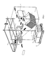
- a cigarette packaging handling device which is capable of arranging cartons 1 in successive layers on a pallet 2 placed in front of the 'apparatus.
- the cartons 1 once filled and closed are gripped by a gripping member 3 represented by a suction cup which is carried by a frame 4 capable of moving in height, and which is arranged on guide bars so as to be able to move longitudinally and transversely in order to bring the cartons 1 each to the location intended for it on the pallet 2.
- the device which will be described below is intended to allow the precise, simple and rapid installation of the pallets 2 at a clearly determined loading location on the loading area which extends in front of the handling device, in order that the automatic movement control members of the suction cup 3 can operate by referring to a predetermined and fixed loading position for the pallet 2.
- a frame 5 which constitutes a support and a base both for the handling device and for the pallet placement device.
- a receptacle 6 which is articulated to the frame at two points 7 aligned along a horizontal axis and on the other hand two transport arms 8 arranged parallel to the ground and capable of moving horizontally in one direction perpendicular to the tilting axis of the receptacle 6 defined by the joints 7.
- the receptacle 6 is a sheet metal part bent and bent in an L-shape so as to define a slide whose rear flank when the receptacle is in the raised position as see it in fig. 2, extends higher than the front flank and whose folded bottom carries a tilting cleat 9 which is articulated at 10 on the front edge of the bottom.
- This sheet metal part also has two symmetrical notches 11 allowing, as will be seen below, the engagement of the arms conveyors 8.
- a jack 12 whose cylinder is fixed by a hinge 13 to the chassis 5 and whose rod is hinged on the rear flank of the slide 6 allows the latter to be maneuvered by tilting it around the axis defined by the hinges 7.
- the arrow A shows this tilting movement of the slide 6.
- each arm 8 we see in FIG. 2 that they are each maneuvered by a jack 14 whose cylinder is rigidly fixed to a rear bar 5a of the chassis 5, and whose axis extends parallel to the direction of movement of the arms 8.
- each arm 8 carries an auxiliary cylinder 15 whose function will be explained later.
- the pallet is placed on the ground in the position 2 ′ so that the transport arm 8 can be moved towards the front from s has position of withdrawal, its front end engaging in one of the notches 11.
- This arm passes freely between the studs of the pallet until a stop which it is provided on its lower surface, stop which is designated par 16, hang a bottom marginal plate of the pallet.
- the forward movement of the arms 8 continues until the positioning movement is completed and during the last part of this movement, the stop 16 drives the pallet 2 so as to release it from the slide 6 which can then be raised by retraction of the jack 12 as seen in FIG. 4.
- the amplitude of the positioning movement of the arm 8 is adjusted by means which will be described later, so that the pallet precisely reaches a loading location designated by 2 ", location in which cartons 1 can be stacked, for example by an automatic handling device which will be programmed according to the 2 "loading location.
- the conveyor arm 8 is capable of carrying out a subsequent displacement from the loading position towards a waiting position by bringing with it the fully loaded pallet and by releasing this pallet in the waiting position, in order to be able to be brought back to the withdrawal position when a new operation of placing an empty pallet must be carried out.
- FIGS. 6, 7 and 8 show a conveyor arm in the loading position, while FIG. 8 shows this conveyor arm during its subsequent displacement.
- Each conveyor arm comprises an elongated body with a U-shaped profile 17.
- On the inner face of the sides of this body 17 are fixed two plates 18 which are opposite and whose front edges constitute the stops 16 determining the position of loading. These plates also serve to support between them a pivot axis 19 on which a roller 20 is mounted.
- the conveyor arm is supported on the other hand by a lateral pin 21 fixed to the external face of one of the sides of the body 17 and to which is connected a rigid bar 22 hinged to the end of the rod 23 of the jack 14.
- Each of the forks 24 and 25 extends forwards and supports at its front end one of the two transport rollers 28 and 29 with a diameter slightly greater than that of the roller 20.
- the forks 24 and 25 are linked by articulations 30 and 31 to a control bar 32.
- the control bar 32 extends at its front end between the two sides of the fork 24, while at its rear end it itself has a fork 33 which embraces the fork 25.
- This fork 33 has on the other hand two vertical uprights 34 which are connected by a hinge pin 35 to which the head 36 of the rod 37 of the jack 15 is fixed.
Abstract
Description
La présente invention a pour objet un dispositif de placement de palettes sur une aire de chargement, comportant un transporteur mobile, muni de moyens moteurs capables de lui imposer un déplacement horizontal de mise en place entre une position de retrait et une position de chargement, en entraînant avec lui dans ce déplacement une palette vide et comportant en outre un réceptacle ajouré, le transporteur étant agencé de manière à dégager une palette du réceptable au cours dudit déplacement de mise en place.The subject of the present invention is a device for placing pallets on a loading area, comprising a mobile conveyor, provided with motor means capable of imposing on it a horizontal displacement of positioning between a withdrawal position and a loading position, in driving with it in this displacement an empty pallet and further comprising an openwork receptacle, the conveyor being arranged so as to release a pallet from the receptacle during said positioning movement.
Un dispositif de ce genre est déjà connu, notamment par le fascicule de demande de brevet FR-2 207 076. Le transporteur est capable de déplacer une à une des palettes empilées dans un réceptacle qui constitue un magasin et de les avancer sur une table de chargement située au-dessus du sol, au niveau de la base de l'empilement des palettes dans le magasin.A device of this kind is already known, in particular from the patent application specification FR-2 207 076. The conveyor is capable of moving one by one the pallets stacked in a receptacle which constitutes a store and of advancing them on a table. load located above the ground, at the base of the stack of pallets in the store.
D'autre part, on connaît des appareils de manutention qui sont capables d'amener et d'arranger automatiquement sur des palettes certains objets de forme simple, présentant tous la même dimension. Ainsi, la demande EP-A-90123 publiée après le dépôt de la présente demande et constituant un état de la technique au sens de l'article 54 (3) CBE, décrit un appareil de manutention qui est associé à un dispositif capable d'engager des cartouches de cigarettes dans des cartons et de fermer ces derniers. Cet appareil de manutention saisit les cartons et les déplace de façon à former des empilements sur une palette.On the other hand, there are known handling devices which are capable of automatically bringing and arranging on pallets certain objects of simple shape, all having the same dimension. Thus, application EP-A-90123 published after the filing of this application and constituting a state of the art within the meaning of Article 54 (3) EPC, describes a handling device which is associated with a device capable of engage cartons of cigarettes in cartons and close them. This handling device picks up the boxes and moves them so as to form stacks on a pallet.
La présente invention résulte de la recherche de moyens automatiques peu encombrants, simples, susceptibles d'être associés à l'appareil de manutention de la demande européenne précitée, et permettant la mise en place des palettes dans une position de changement déterminée de façon précise, et leur évacuation après leur chargement de manière systématique et rapide. Bien entendu, le dispositif selon la présente invention peut être associé à diverses installations automatiques de distribution et de transport d'objets. Il peut également être associé à des opérations de chargement faites de façon entièrement manuelle.The present invention results from the search for compact, simple, automatic means capable of being associated with the handling device of the aforementioned European request, and allowing the placing of the pallets in a change position determined precisely, and their evacuation after loading in a systematic and rapid manner. Of course, the device according to the present invention can be associated with various automatic installations for distributing and transporting objects. It can also be combined with fully manual loading operations.
Selon la présente invention, le dispositif de placement de palettes du genre mentionné au début est caractérisé en ce que le réceptable est capable de basculer autour d'un axe horizontal entre une position de réception et une position de rabattement, et de supporter dans la position de réception la palette placée sur sa tranche, et en ce que le transporteur est agencé de manière à s'engager dans la palette disposée dans le réceptacle ajouré quand ce dernier est en position de rabattement.According to the present invention, the pallet placement device of the kind mentioned at the beginning is characterized in that the receptacle is capable of tilting around a horizontal axis between a receiving position and a folding position, and of supporting in the position receiving the pallet placed on its edge, and in that the transporter is arranged so as to engage in the pallet disposed in the perforated receptacle when the latter is in the folded position.
On va décrire ci-après à titre d'exemple une forme d'exécution du dispositif suivant l'invention en se référant au dessin annexé, dont :
- la figure 1 est une vue en perspective schématique et simplifiée d'un appareil de manutention de cartons de cigarettes connu en soi et auquel le dispositif selon l'invention peut être associé,
- la figure 2 est une vue en perspective schématique et simplifiée du dispositif de placement de palettes associé à l'appareil de manutention de la fig. 1,
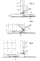
- les figures 3, 4 et 5 sont des vues en élévation schématiques montrant les phases du fonctionnement du dispositif de placement de palettes,
- la figure 6 est une vue en coupe verticale du dispositif montrant un bras transporteur dans la position de chargement,
- la figure 7 est une vue en coupe horizontale partielle du bras transporteur visible à la fig. 6, et
- la figure 8 est une vue en élévation partielle du bras transporteur de la fig. 6 montrant ce bras dans sa position au cours d'un déplacement ultérieur.
- FIG. 1 is a schematic and simplified perspective view of an apparatus for handling cigarette cartons known per se and with which the device according to the invention can be associated,
- Figure 2 is a schematic and simplified perspective view of the pallet placement device associated with the handling device of FIG. 1,
- FIGS. 3, 4 and 5 are schematic elevation views showing the phases of operation of the pallet placement device,
- FIG. 6 is a vertical section view of the device showing a conveyor arm in the loading position,
- Figure 7 is a partial horizontal sectional view of the conveyor arm visible in FIG. 6, and
- FIG. 8 is a partial elevation view of the conveyor arm of FIG. 6 showing this arm in its position during a subsequent movement.
Avant de passer à la description détaillée du dispositif de placement des palettes, on rappellera rapidement qu'on connaît déjà un appareil de manutention d'emballage de cigarettes qui est capable d'arranger des cartons 1 en couches successives sur une palette 2 placée devant l'appareil. Les cartons 1 une fois remplis et fermés sont saisis par un organe de préhension 3 représenté par une ventouse qui est portée par un châssis 4 capable de se déplacer en hauteur, et qui est agencée sur des barres de guidage der façon à pouvoir se déplacer longitudinalement et transversalement afin d'amener les cartons 1 chacun à l'emplacement qui lui est destiné sur la palette 2.Before proceeding to the detailed description of the pallet placement device, it will quickly be recalled that a cigarette packaging handling device is already known which is capable of arranging
Le dispositif qui va être décrit ci-après est destiné à permettre la mise en place précise, simple et rapide des palettes 2 à un emplacement de chargement bien déterminé sur l'aire de chargement qui s'étend devant l'appareil de manutention, afin que les organes de commande automatique des déplacements de la ventouse 3 puissent fonctionner en se référant à une position de chargement prédéterminée et fixe pour la palette 2. On voit à la fig. 2 la partie inférieure d'un châssis 5 qui constitue un support et un socle aussi bien pour l'appareil de manutention que pour le dispositif de placement des palettes. A ce châssis 5 sont accrochés d'une part un réceptacle 6 qui est articulé au châssis en deux points 7 aligné selon un axe horizontal et d'autre part deux bras transporteurs 8 disposés parallèlement sur le sol et capables de se déplacer horizontalement dans une direction perpendiculaire à l'axe de basculement du réceptacle 6 défini par les articulations 7. Le réceptacle 6 est une pièce de tôle pliée et coudée en forme de L de façon à définir une coulisse dont le flanc arrière lorsque le réceptacle est en position relevée comme on le voit à la fig. 2, s'étend plus haut que le flanc avant et dont le fond rabattu porte un taquet basculant 9 qui est articulé en 10 sur le bord antérieur du fond. Cette pièce de tôle présente en outre deux échancrures symétriques 11 permettant comme on le verra plus loin l'engagement des bras transporteurs 8. Un vérin 12 dont le cylindre est fixé par une articulation 13 au châssis 5 et dont la tige est articulée sur le flanc arrière de la coulisse 6 permet de manoeuvrer cette dernière en la faisant basculer autour de l'axe défini par les articulations 7. La flèche A montre ce mouvement de basculement de la coulisse 6.The device which will be described below is intended to allow the precise, simple and rapid installation of the
Quant aux bras transporteurs 8, on voit à la fig. 2 qu'ils sont manoeuvrés chacun par un vérin 14 dont le cylindre est rigidement fixé à une barre arrière 5a du châssis 5, et dont l'axe s'étend parallèlement à la direction du déplacement des bras 8. De plus, chaque bras 8 porte un vérin auxiliaire 15 dont la fonction sera expliquée plus loin.As for the
A la fig. 2 on voit également que la coulisse 6 est représentée d'une part en traits pleins dans sa position relevée, et d'autre part en traits mixtes dans sa position rabattue, une palette 2 étant représentée en traits mixtes dans la position de réception et en position 2' dans la position de rabattement, tandis que la position 2" montre la même palette en position de chargement. Ces trois positions sont également visibles aux fig. 3, 4 et 5 où l'on voit à nouveau représentés schématiquement le châssis 5, le vérin de basculement 12, la coulisse 6 et un des bras transporteurs 8. A la fig. 3 la coulisse 6 est dans sa position de réception et une palette 2 peut être engagée sur sa tranche dans cette coulisse de façon à être accrochée par le taquet 9 qui la retient en place en position verticale. Au cours du basculement de la coulisse 6 illustré par la flèche A, la palette vient se placer sur le sol dans la position 2' de sorte que le bras transporteur 8 peut être déplacé vers l'avant à partir de sa position de retrait, son extrémité antérieure s'engageant dans l'une des échancrures 11. Ce bras passe librement entre les plots de la palette jusqu'à ce qu'une butée dont il est pourvu sur sa surface inférieure, butée qui est désignée par 16, accroche une plaque marginale inférieure de la palette. Le mouvement d'avance des bras 8 se poursuit jusqu'à ce que le déplacement de mise en place soit terminé et pendant la dernière partie de ce déplacement, la butée 16 entraîne la palette 2 de façon à la dégager de la coulisse 6 qui peut ensuite être relevée par rétraction du vérin 12 comme on le voit à la fig. 4. L'amplitude du déplacement de mise en place du bras 8 est réglée par des moyens qui seront décrits plus loin, de sorte que la palette atteint avec précision un emplacement de chargement désigné par 2", emplacement dans lequel des cartons 1 peuvent être empilés, par exemple par un appareil de manutention automatique qui sera programmé en fonction de l'emplacement de chargement 2".In fig. 2 it can also be seen that the
Pendant que le chargement s'effectue comme on le voit à la fig. 5, et lorsque la première couche est palettisée, on peut mettre en place une nouvelle palette 2"' sur la coulisse 6 qui a été relevée et ramenée dans sa position de réception.While loading takes place as shown in fig. 5, and when the first layer is palletized, a
Finalement, le bras transporteur 8 est capable d'effectuer un déplacement ultérieur à partir de la position de chargement vers une position d'attente en amenant avec lui la palette entièrement chargée et en libérant cette palette dans la position d'attente, afin de pouvoir être ramené en position de retrait au moment où une nouvelle opération de mise en place d'une palette vide doit être effectuée.Finally, the
La conformation des bras transporteurs 8 est représentée plus en détail aux fig. 6, 7 et 8. Les fig. 6 et 7 montrent un bras transporteur dans la position de chargement, tandis que la fig. 8 montre ce bras transporteur au cours de son déplacement ultérieur. Chaque bras transporteur comporte un corps allongé à profil en U 17. Sur la face intérieure des flancs de ce corps 17 sont fixées deux plaquettes 18 qui se trouvent en vis-à- vis et dont les bords antérieurs constituent les butées 16 déterminant la position de chargement. Ces plaquettes servent en outre à supporter entre elles un axe de pivotement 19 sur lequel est monté un galet 20. Le bras transporteur est supporté d'autre part par un tourillon latéral 21 fixé à la face extérieure d'un des flancs du corps 17 et auquel est reliée une barre rigide 22 articulée à l'extrémité de la tige 23 du vérin 14. Comme l'extrémité arrière du cylindre de ce vérin 14 est rigidement fixée comme on l'a dit précédemment à la barre 5a du châssis 5, le bras 8 est entièrement guidé dans une direction perpendiculaire à l'axe de basculement de la coulisse 6 par le galet 20 et par la liaison entre la tige 23 et le corps 17. A l'intérieur du profil en U du corps 17 est monté un train de galets extractibles. Deux fourches 24 et 25 sont articulées sur des axes 26 et 27 dont les extrémités sont liées aux flancs du corps 17. Ces deux axes d'articulation 26 et 27 se trouvent respectivement à l'extrémité avant et au voisinage de l'extrémité arrière du corps 17. Chacune des fourches 24 et 25 s'étend vers l'avant et supporte à son extrémité avant l'un des deux galets de transport 28 et 29 de diamètre légèrement supérieur à celui du galet 20. Enfin, à leurs extrémités arrières, les fourches 24 et 25 sont liées par des articulations 30 et 31 à une barre de commande 32. Comme on le voit à la fig. 7, la barre de commande 32 s'étend à son extrémité avant entre les deux flancs de la fourche 24, tandis qu'à son extrémité arrière elle présente elle-même une fourche 33 qui embrasse la fourche 25. Cette fourche 33 présente d'autre part deux montants verticaux 34 qui sont reliés par un axe d'articulation 35 auquel est fixée la tête 36 de la tige 37 du vérin 15. Le cylindre de ce vérin étant articulé d'autre part par son extrémité arrière sur le côté supérieur du corps 17, on voit que la manoeuvre du vérin fait avancer la barre de commande 32 vers l'avant, ce qui fait basculer les deux fourches 24 et 25 autour de leurs articulations 30 et 31. Les galets 28 et 29 sont déplacés vers le bas au cours de ce pivotement et viennent s'appuyer sur le sol en soulevant le bras 8 comme le montre la fig. 8. Le galet 20 quitte alors le sol et la palette 2 dans laquelle les bras transporteurs 8 sont engagés est aussi soulevée, ce qui permet de transporter la palette chargée sur une distance au moins égale à une largeur de palette et par conséquent de dégager entièrement l'aire de chargement. La rétraction du vérin 15 ramène le bras transporteur dans la position de la fig. 7, de sorte que le vérin 14 peut le ramener dans sa position de retrait en laissant la palette chargée dans la position d'attente.The configuration of the
On se rend compte que le fonctionnement du dispositif décrit peut être automatisé si la commande des bras transporteurs est liée à la détection de leur position. Ainsi, on peut fixer au bras transporteur un organe de commande capable de coopérer avec des contacteurs eux-mêmes placés à des emplacements fixes correspondant aux positions prévues, c.-à.-d. la position de retrait, la position de chargement et la position d'attente. Comme la butée 16 entraîne nécessairement la palette 2 au moment où elle entre en contact avec elle, la position de cette palette est liée à celle du bras transporteur, de sorte que la commande des opérations du bras transporteur a pour effet de positionner la palette aux emplacements voulus.We realize that the operation of the device described can be automated if the control of the transport arms is linked to the detection of their position. Thus, it is possible to attach to the conveyor arm a control member capable of cooperating with contactors themselves placed at fixed locations corresponding to the positions provided, ie. the withdrawal position, the loading position and the standby position. As the
L'engagement d'une palette placée sur sa tranche dans la coulisse 6 est une opération très simple et il suffit qu'elle soit menée jusqu'à ce que le bord avant de la palette butte contre le fond rabattu de la coulisse pour que le positionnement soit assuré, le taquet basculant 9 retenant la palette en position verticale. Après le rabattement il bascule autour de son articulation 10 vers l'avant sous l'effet de la poussée de la palette pendant le dégagement de celle-ci et lorsque la coulisse reprend sa position verticale il retombe, sous l'effet de son poids dans la position de la fig. 2 et il est retenu par une butée d'appui (non représentée). Le stockage des palettes vides en position verticale économise de la place et facilite la manutention. Enfin, grâce à ce mode de mise en place, la précision des opérations ultérieures est assurée.The engagement of a pallet placed on its edge in the
Claims (9)
Priority Applications (4)
| Application Number | Priority Date | Filing Date | Title |
|---|---|---|---|
| AT83810308T ATE25650T1 (en) | 1983-07-06 | 1983-07-06 | DEVICE FOR PLACING PALLETS ON A LOADING STATION. |
| EP83810308A EP0131082B1 (en) | 1983-07-06 | 1983-07-06 | Device for placing pallets on a loading area |
| DE8383810308T DE3369954D1 (en) | 1983-07-06 | 1983-07-06 | Device for placing pallets on a loading area |
| US06/750,232 US4613032A (en) | 1983-07-06 | 1985-06-28 | Apparatus for placing pallets on a loading surface |
Applications Claiming Priority (1)
| Application Number | Priority Date | Filing Date | Title |
|---|---|---|---|
| EP83810308A EP0131082B1 (en) | 1983-07-06 | 1983-07-06 | Device for placing pallets on a loading area |
Publications (2)
| Publication Number | Publication Date |
|---|---|
| EP0131082A1 EP0131082A1 (en) | 1985-01-16 |
| EP0131082B1 true EP0131082B1 (en) | 1987-03-04 |
Family
ID=8191557
Family Applications (1)
| Application Number | Title | Priority Date | Filing Date |
|---|---|---|---|
| EP83810308A Expired EP0131082B1 (en) | 1983-07-06 | 1983-07-06 | Device for placing pallets on a loading area |
Country Status (4)
| Country | Link |
|---|---|
| US (1) | US4613032A (en) |
| EP (1) | EP0131082B1 (en) |
| AT (1) | ATE25650T1 (en) |
| DE (1) | DE3369954D1 (en) |
Families Citing this family (10)
| Publication number | Priority date | Publication date | Assignee | Title |
|---|---|---|---|---|
| DE3862150D1 (en) * | 1987-05-14 | 1991-05-02 | Erwin Jenkner | METHOD AND SYSTEM FOR TRANSFERING TRANSPORT PLATFORMS TO THE LIFTING TABLE OF A STACKING STATION. |
| DE3717628A1 (en) * | 1987-05-26 | 1988-12-15 | Loehr & Herrmann Gmbh | DEVICE FOR INPUTING AND OUTPUTING PCBS IN SLOTED REPLACEMENT PALLETS |
| FR2649684B1 (en) * | 1989-07-12 | 1992-02-21 | Prosyn Polyane | RECOVERY DEVICE AND METHOD FOR STORING TUBULAR SHEATH AFTER CROSS-BENDING |
| GB2304679B (en) * | 1995-08-25 | 1999-06-30 | Chep Uk Ltd | Handling apparatus and system |
| US6430800B1 (en) | 1997-03-19 | 2002-08-13 | Libla Industries | Automatic pallet fabrication apparatus and methods |
| US6547511B1 (en) * | 2000-10-30 | 2003-04-15 | Owens Corning Fiberglas Technology, Inc. | Process of loading rolls of roofing material onto a pallet |
| GB2369614B (en) * | 2000-12-04 | 2004-07-07 | Ssi Schaefer Ltd | Pallet handling method and apparatus |
| US9004839B2 (en) * | 2011-10-18 | 2015-04-14 | Shenzhen China Star Optoelectronics Technology Co., Ltd. | Glass substrate storage and transportation system and a glass substrate storage platform |
| RU2634737C1 (en) * | 2016-05-11 | 2017-11-03 | Спектрум Импорт Экспорт Лимитед | Method for pan replacement and device for its implementation |
| WO2024004536A1 (en) * | 2022-06-27 | 2024-01-04 | 村田機械株式会社 | Automated storage and retrieval system |
Family Cites Families (10)
| Publication number | Priority date | Publication date | Assignee | Title |
|---|---|---|---|---|
| US1498732A (en) * | 1923-05-12 | 1924-06-24 | Robert J Jauch | Automatic feeder for soap-cutting tables |
| DE941600C (en) * | 1941-03-11 | 1956-04-12 | Siemag Siegener Maschb Ges Mit | Device for stacking and forwarding wound tapes and wire coils |
| DE1038472B (en) * | 1957-02-12 | 1958-09-04 | Schlosser & Co G M B H | Method and device for changing production plates in a molding machine |
| US2894648A (en) * | 1957-04-11 | 1959-07-14 | Clarence W Mussett | Stacking device |
| US2985323A (en) * | 1957-04-29 | 1961-05-23 | Royal Container Co | Machine for packaging cartons |
| US3384249A (en) * | 1965-07-12 | 1968-05-21 | United Eng Foundry Co | Piler stacker apparatus |
| FR2207076B3 (en) * | 1972-11-21 | 1976-01-09 | Ribes Rene Fr | |
| SU581035A1 (en) * | 1976-05-03 | 1977-11-25 | Трест Пуско-Наладочных,Проектно-Конструкторских Работ И Научной Организации Труда "Оргтехстром" | Rod-type feed impeller |
| US4119214A (en) * | 1977-04-13 | 1978-10-10 | Electric Terminal Corporation | Method and device for loading stock into a machine |
| SU734104A1 (en) * | 1977-10-24 | 1980-05-15 | Производственно-Техническое Объединение "Оргтехстром" | Automatic machine for depositing reels |
-
1983
- 1983-07-06 EP EP83810308A patent/EP0131082B1/en not_active Expired
- 1983-07-06 AT AT83810308T patent/ATE25650T1/en not_active IP Right Cessation
- 1983-07-06 DE DE8383810308T patent/DE3369954D1/en not_active Expired
-
1985
- 1985-06-28 US US06/750,232 patent/US4613032A/en not_active Expired - Fee Related
Also Published As
| Publication number | Publication date |
|---|---|
| EP0131082A1 (en) | 1985-01-16 |
| US4613032A (en) | 1986-09-23 |
| ATE25650T1 (en) | 1987-03-15 |
| DE3369954D1 (en) | 1987-04-09 |
Similar Documents
| Publication | Publication Date | Title |
|---|---|---|
| EP0354873B1 (en) | Depalletizer for parcels of labels | |
| FR2499039A1 (en) | DEVICE FOR INSERTING SHEET PACKETS INTO A WORKING MACHINE | |
| EP0131082B1 (en) | Device for placing pallets on a loading area | |
| CA2004409C (en) | Cartoning machine used to automatically put an item, especially a vial, in a case | |
| WO2008047008A1 (en) | Machine for shaping blanks of cardboard boxes | |
| EP3464075B1 (en) | Vibrating device for the ordered rearrangement of folding boxes in a container, discharge conveyor and method for discharging containers | |
| CA2068457A1 (en) | Device for bin filling, especially from a mail sorting machine | |
| EP0395459A1 (en) | Self-contained freight loading and unloading device integrated in an aircraft | |
| EP1666365A1 (en) | Palletcontainer with two support surfaces | |
| EP1060988A1 (en) | Method and device for making and applying a flexible heat-shrinkable hood on palletized load | |
| EP0624334B1 (en) | Display unit inclined towards front for sale of diverse articles | |
| CA2000478A1 (en) | Automatic food dispenser for bread and process for the management and distribution of products | |
| EP0188987B1 (en) | Palettizer, in particular for bag parcels | |
| EP1012090B1 (en) | Device for presenting and adjusting a stock box for removing or storing articles | |
| FR2673612A1 (en) | Device for destacking and automatic dispensing of trays | |
| FR2720761A1 (en) | Laundry folding assembly | |
| EP0255448B1 (en) | Device for handling crates, especially crates with a mobile bottom to handle goods at a constant level | |
| FR2623472A1 (en) | Chain for automatic palletisation of stacked packages | |
| EP0204606B1 (en) | Apparatus for erecting, filling and paletising containers | |
| FR2562523A1 (en) | System for transferring objects between two devices, one of which comprises an assembly of vertical spaced plates | |
| EP0277844A1 (en) | Method for putting small products from containers into a container, and system for performing the method | |
| FR2639611A1 (en) | Device for placing a cover over a load packaged by means of hoop-casing | |
| EP0277880B1 (en) | Handling device, in particular for self-service shops | |
| FR2930237A1 (en) | Foldable container for e.g. transporting vehicle gearbox, has foldable support maintaining plate in plane parallel to base during displacement of plate between upper usage position and lower folded position in which plate rests on base | |
| FR2517278A1 (en) | DEVICE FOR THE RESERVATION OF BULBS FORMED FROM STACKED BAGS, FOR THE SUPPLY OF A BAGGING STATION |
Legal Events
| Date | Code | Title | Description |
|---|---|---|---|
| PUAI | Public reference made under article 153(3) epc to a published international application that has entered the european phase |
Free format text: ORIGINAL CODE: 0009012 |
|
| 17P | Request for examination filed |
Effective date: 19840615 |
|
| AK | Designated contracting states |
Designated state(s): AT BE CH DE FR GB IT LI LU NL SE |
|
| GRAA | (expected) grant |
Free format text: ORIGINAL CODE: 0009210 |
|
| AK | Designated contracting states |
Kind code of ref document: B1 Designated state(s): AT BE CH DE FR GB IT LI LU NL SE |
|
| REF | Corresponds to: |
Ref document number: 25650 Country of ref document: AT Date of ref document: 19870315 Kind code of ref document: T |
|
| REF | Corresponds to: |
Ref document number: 3369954 Country of ref document: DE Date of ref document: 19870409 |
|
| ITF | It: translation for a ep patent filed |
Owner name: STUDIO TORTA SOCIETA' SEMPLICE |
|
| PLBE | No opposition filed within time limit |
Free format text: ORIGINAL CODE: 0009261 |
|
| STAA | Information on the status of an ep patent application or granted ep patent |
Free format text: STATUS: NO OPPOSITION FILED WITHIN TIME LIMIT |
|
| 26N | No opposition filed | ||
| ITTA | It: last paid annual fee | ||
| EPTA | Lu: last paid annual fee | ||
| EAL | Se: european patent in force in sweden |
Ref document number: 83810308.3 |
|
| PGFP | Annual fee paid to national office [announced via postgrant information from national office to epo] |
Ref country code: FR Payment date: 19970613 Year of fee payment: 15 |
|
| PGFP | Annual fee paid to national office [announced via postgrant information from national office to epo] |
Ref country code: AT Payment date: 19970616 Year of fee payment: 15 |
|
| PGFP | Annual fee paid to national office [announced via postgrant information from national office to epo] |
Ref country code: BE Payment date: 19970617 Year of fee payment: 15 |
|
| PGFP | Annual fee paid to national office [announced via postgrant information from national office to epo] |
Ref country code: SE Payment date: 19970618 Year of fee payment: 15 |
|
| PGFP | Annual fee paid to national office [announced via postgrant information from national office to epo] |
Ref country code: GB Payment date: 19970620 Year of fee payment: 15 |
|
| PGFP | Annual fee paid to national office [announced via postgrant information from national office to epo] |
Ref country code: DE Payment date: 19970623 Year of fee payment: 15 |
|
| PGFP | Annual fee paid to national office [announced via postgrant information from national office to epo] |
Ref country code: NL Payment date: 19970630 Year of fee payment: 15 Ref country code: CH Payment date: 19970630 Year of fee payment: 15 |
|
| PGFP | Annual fee paid to national office [announced via postgrant information from national office to epo] |
Ref country code: LU Payment date: 19970908 Year of fee payment: 15 |
|
| PG25 | Lapsed in a contracting state [announced via postgrant information from national office to epo] |
Ref country code: LU Free format text: LAPSE BECAUSE OF NON-PAYMENT OF DUE FEES Effective date: 19980706 Ref country code: GB Free format text: LAPSE BECAUSE OF NON-PAYMENT OF DUE FEES Effective date: 19980706 Ref country code: AT Free format text: LAPSE BECAUSE OF NON-PAYMENT OF DUE FEES Effective date: 19980706 |
|
| PG25 | Lapsed in a contracting state [announced via postgrant information from national office to epo] |
Ref country code: SE Free format text: LAPSE BECAUSE OF NON-PAYMENT OF DUE FEES Effective date: 19980707 |
|
| PG25 | Lapsed in a contracting state [announced via postgrant information from national office to epo] |
Ref country code: LI Free format text: LAPSE BECAUSE OF NON-PAYMENT OF DUE FEES Effective date: 19980731 Ref country code: CH Free format text: LAPSE BECAUSE OF NON-PAYMENT OF DUE FEES Effective date: 19980731 Ref country code: BE Free format text: LAPSE BECAUSE OF NON-PAYMENT OF DUE FEES Effective date: 19980731 |
|
| BERE | Be: lapsed |
Owner name: S.A. FABRIQUES DE TABAC REUNIES Effective date: 19980731 |
|
| PG25 | Lapsed in a contracting state [announced via postgrant information from national office to epo] |
Ref country code: NL Free format text: LAPSE BECAUSE OF NON-PAYMENT OF DUE FEES Effective date: 19990201 |
|
| GBPC | Gb: european patent ceased through non-payment of renewal fee |
Effective date: 19980706 |
|
| REG | Reference to a national code |
Ref country code: CH Ref legal event code: PL |
|
| EUG | Se: european patent has lapsed |
Ref document number: 83810308.3 |
|
| PG25 | Lapsed in a contracting state [announced via postgrant information from national office to epo] |
Ref country code: FR Free format text: LAPSE BECAUSE OF NON-PAYMENT OF DUE FEES Effective date: 19990331 |
|
| NLV4 | Nl: lapsed or anulled due to non-payment of the annual fee |
Effective date: 19990201 |
|
| PG25 | Lapsed in a contracting state [announced via postgrant information from national office to epo] |
Ref country code: DE Free format text: LAPSE BECAUSE OF NON-PAYMENT OF DUE FEES Effective date: 19990501 |
|
| REG | Reference to a national code |
Ref country code: FR Ref legal event code: ST |