EP0129810B1 - Verfahren zum Stabilisieren eines Seeschiffs mit einem Schiffsruder - Google Patents
Verfahren zum Stabilisieren eines Seeschiffs mit einem Schiffsruder Download PDFInfo
- Publication number
- EP0129810B1 EP0129810B1 EP84106913A EP84106913A EP0129810B1 EP 0129810 B1 EP0129810 B1 EP 0129810B1 EP 84106913 A EP84106913 A EP 84106913A EP 84106913 A EP84106913 A EP 84106913A EP 0129810 B1 EP0129810 B1 EP 0129810B1
- Authority
- EP
- European Patent Office
- Prior art keywords
- rudder
- hydraulic medium
- swivelling
- movements
- movement
- Prior art date
- Legal status (The legal status is an assumption and is not a legal conclusion. Google has not performed a legal analysis and makes no representation as to the accuracy of the status listed.)
- Expired
Links
- 238000000034 method Methods 0.000 title claims abstract description 8
- 230000000087 stabilizing effect Effects 0.000 title description 5
- 230000006641 stabilisation Effects 0.000 claims abstract description 12
- 238000005096 rolling process Methods 0.000 claims abstract description 10
- 230000003019 stabilising effect Effects 0.000 claims abstract 4
- 238000011105 stabilization Methods 0.000 description 10
- 238000010586 diagram Methods 0.000 description 4
- 230000000694 effects Effects 0.000 description 4
- 241000380131 Ammophila arenaria Species 0.000 description 2
- 230000001276 controlling effect Effects 0.000 description 2
- 239000003921 oil Substances 0.000 description 2
- 238000005265 energy consumption Methods 0.000 description 1
- 230000006870 function Effects 0.000 description 1
- 239000010720 hydraulic oil Substances 0.000 description 1
- 230000000977 initiatory effect Effects 0.000 description 1
- 239000007788 liquid Substances 0.000 description 1
- 230000007257 malfunction Effects 0.000 description 1
- 230000007935 neutral effect Effects 0.000 description 1
- 230000001105 regulatory effect Effects 0.000 description 1
Images

Classifications
-
- G—PHYSICS
- G05—CONTROLLING; REGULATING
- G05D—SYSTEMS FOR CONTROLLING OR REGULATING NON-ELECTRIC VARIABLES
- G05D1/00—Control of position, course, altitude or attitude of land, water, air or space vehicles, e.g. using automatic pilots
- G05D1/08—Control of attitude, i.e. control of roll, pitch, or yaw
- G05D1/0875—Control of attitude, i.e. control of roll, pitch, or yaw specially adapted to water vehicles
-
- B—PERFORMING OPERATIONS; TRANSPORTING
- B63—SHIPS OR OTHER WATERBORNE VESSELS; RELATED EQUIPMENT
- B63H—MARINE PROPULSION OR STEERING
- B63H25/00—Steering; Slowing-down otherwise than by use of propulsive elements; Dynamic anchoring, i.e. positioning vessels by means of main or auxiliary propulsive elements
- B63H25/02—Initiating means for steering, for slowing down, otherwise than by use of propulsive elements, or for dynamic anchoring
- B63H25/04—Initiating means for steering, for slowing down, otherwise than by use of propulsive elements, or for dynamic anchoring automatic, e.g. reacting to compass
-
- B—PERFORMING OPERATIONS; TRANSPORTING
- B63—SHIPS OR OTHER WATERBORNE VESSELS; RELATED EQUIPMENT
- B63B—SHIPS OR OTHER WATERBORNE VESSELS; EQUIPMENT FOR SHIPPING
- B63B39/00—Equipment to decrease pitch, roll, or like unwanted vessel movements; Apparatus for indicating vessel attitude
- B63B39/06—Equipment to decrease pitch, roll, or like unwanted vessel movements; Apparatus for indicating vessel attitude to decrease vessel movements by using foils acting on ambient water
Definitions
- the invention relates to a method for stabilizing an ocean-going vessel against rolling movements by means of reciprocating pivoting movements of the ship's rudder, which is moved by a hydraulic rowing machine, the pivoting movements for stabilization having to be carried out at a higher rotational speed than in conventional rowing, the movement of the rudder and the setting of a rudder angle is controlled by an influenceable supply of a hydraulic medium to the rowing machine and the control of the supply takes place as a function of the rudder position selected at the helm for keeping the course and of the rolling movements determined by a roll sensor.
- Such a conventional system is e.g. B. from a feed pump that continuously sucks hydraulic oil from a tank and from a control valve that can be moved in three positions, namely for returning the oil from the pump to the tank with a fixed rudder and for supplying and returning the oil to the rowing machine to turn the rudder in either direction until the desired rudder position is reached.
- Safety and non-return valves are provided on the lines to prevent the rudder from e.g. gets out of control due to a leaky hydraulic line.
- a rudder rotation speed of 0.087 rad / sec, corresponding to approximately 5 degrees per second is customary, and a rudder range of approximately 35 to 40 ° is required on each side, which is also necessary for maneuvers when driving slowly.
- a rudder rotation speed of 0.087 rad / sec, corresponding to approximately 5 degrees per second
- a rudder range of approximately 35 to 40 ° is required on each side, which is also necessary for maneuvers when driving slowly.
- a rudder range of approximately 35 to 40 ° is required on each side, which is also necessary for maneuvers when driving slowly.
- relatively large swivel angles for stabilizing at service speed also require large rudder forces which cannot be applied by the usual rudder drives.
- the invention has for its object to provide a method for stabilizing seagoing vessels by means of oars, which are driven by hydraulic rowing machines, and in particular to design and operate the hydraulic system required for this in such a way that the rapid oar movements required for stabilization . can be done in an energy-saving manner.
- the supply of the hydraulic medium to the rowing machine takes place via a control device from a pressure system into which the hydraulic medium is continuously conveyed until a full operating pressure is reached and in which the rudder is stopped during normal rowing , as well as after a swiveling movement when the rudder remains at a certain angle and that for a movement of the rudder the hydraulic medium is simultaneously supplied via the opened control device from the stored volume and from the constant delivery, the rudder area, in which stabilizing swivel movements can be carried out, is smaller than the maximum rudder area required to control the seagoing ship from the helm.
- the rudder standstill can be used to store the hydraulic medium in order to compensate for short-term peak loads.
- the supply of the hydraulic medium from the pressure system is controlled in the control device with respect to the flow time, flow current and flow direction.
- a rudder blade be used, on the rear edge of which a fin which is additionally moved according to the rudder position and is mechanically coupled to the rudder blade is arranged.
- the effect of the rudder blade is at a rudder angle set in the rowing machine and thus also on the rudder blade
- the swivel angle of the rowing machine and the rudder blade can be enlarged or smaller, so that the time for the supply of the hydraulic medium until this swivel angle is reached is shorter.
- the method according to the invention is suitable both for roll stabilization and for control. It can therefore be used with a second drive system for the rowing machine, which is useful for safety reasons in addition to a conventional drive system.
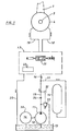
- the system comprises a pump 11 with a constant delivery rate, which is connected to a tank 13 by a suction line 12.
- the pump 11 is driven by a motor 30.
- the delivery line 15 is connected to a pressure accumulator 14 via a connecting line 31.
- Pump 11 and accumulator 14 can convey the hydraulic medium via a delivery line 16 to a control device 17, which is connected via lines 18, 19 to the rowing machine 4.
- a control device 17 which is connected via lines 18, 19 to the rowing machine 4.
- one of the lines 18, 19 is the feed line and the other the discharge line, depending on the direction of the rowing movement.
- the flowing back medium is fed back via the control device into a drain line 20 and further into the tank 13.
- the control device 17 contains a position-controlled proportional directional valve 21 (proportional control valve) and a discharge pressure compensator 22 (load compensation device), which are known in principle for controlling the flow of a liquid medium.
- the valve 21 is controlled by electrical signals from an electrical circuit, not shown, and in dependence on signals for controlling and reducing the rolling movements.
- a hydraulic servo motor which is contained in the valve device 21, the valve is opened or brought into a position in which it controls the flow of the hydraulic medium in one direction or the other and in which it is more or less open to the To regulate the flow rate depending on the electrical signal.
- the discharge pressure compensator 22 is also able to control the quantity and pressure of the hydraulic medium flowing back from the rowing machine 4 and to compensate for changing loads or forces acting on the rudder due to waves or sea impact, so that the rotation speed of the rudder is caused exclusively by the inflow of the medium from the memory-based pump 11 and according to the setting of the valve 21.
- the controller 17 includes other valves, such as check and distribution valves and safety devices, which return the valve 21 to a neutral position if any malfunction occurs. These devices are not shown in the figures, since they can be designed and arranged in a manner familiar to the person skilled in the art.
- the feed pump 11 continuously delivers hydraulic medium into the feed line 15 through a check valve 34.
- a pressure relief valve 33 is opened by a pressure gauge 32 and the feed stream is returned to the tank 13 without pressure, so that the pump runs at idle.
- valve 21 If the valve 21 is opened to pivot the rudder 1, the hydraulic medium flows into a chamber or into a group of chambers of the rowing machine 4, the full operating pressure of, for example, 150 bar from the reservoir 14 being effective from the start. During the movement of the rowing machine 4, the operating pressure is essentially maintained by the delivery of the pump 11 in addition to the delivery from the store 14. After a rowing movement, the reservoir 14 is refilled by the pump 11.
- Fig. 3 shows, movements of the rudder have to lead the rolling tendency of the ship, but after a swiveling movement the rudder remains at a certain angle before the next movement is initiated.
- the diagram shows in dash-dotted lines a possible angle B, for example, of the tendency to roll of an unstabilized ship, which is assumed to roll according to curve R for a certain time T.
- a possible angle B for example, of the tendency to roll of an unstabilized ship, which is assumed to roll according to curve R for a certain time T.
- the rudder is to be placed in a rudder angle A in each case and must be moved and held in the time shown in accordance with curve S shown in a solid line.
- the rudder must be turned to the port at an angle of 20 °, at such a speed that the angle is reached at instant t 2 .
- the rudder remains in this position until the moment t 3 , in which an opposite movement to the starboard is required, etc.
- the control device 17 is opened to allow an inflow of the hydraulic medium from the pump 11 and from memory 14 to the rowing machine 4 in such a way that at the instant t 2 the rudder is stopped in the required position, the rudder rotation speed being determined by the flow rate set in the control device 17.
- the reservoir is refilled to the full working pressure by the pump 11.
- the roll frequency at which roll stabilization is desirable is usually around 8 to 10 seconds, but frequencies between 3 and 30 seconds are also possible.
- the rudder position must therefore be changed at relatively short intervals, with speeds of up to 45 ° / s being possible. This leads to high rudder torques and high energy consumption during the rudder movement.
- the delivery rate of the pump can be reduced according to the invention to approximately 50% of the output to the rowing machine in order to bring about a maximum rudder movement, since the remaining 50% of the maximum output can be supplied by the pressure accumulator, whose capacity is to be selected accordingly.
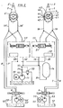
- FIG. 2 shows the application of the invention to a double rudder system.
- the parts are essentially the same as previously described for a single rudder, but some reference numerals assigned to the parts of the second rudder are identified by an additional line, such as rudder 1 '.
- a control device 17, 17 ' is provided for each of the rudders 1, 1', but the hydraulic medium can be supplied by a single pump 11, which is supported by a pressure accumulator 14.
- FIG. 2 shows a further rudder drive of conventional type, which is expedient for safety reasons, for each of the two rudders, which is designed for normal rudder movements for steering over the full rudder angle but with a low rudder rotation speed.
- This further rudder drive comprises a feed pump 5, 5 ', an electrically operated control valve 6, 6' which controls the flow time and direction of flow of the hydraulic medium to and from the rowing machine 4,4 'through lines 7, 7' and 8, 8 '. which are connected to corresponding lines 18, 18 'and 19, 19' on the rowing machine 4, 4 '. Further useful valves in these lines are not shown, since their arrangement is generally known and in some cases also prescribed.
- the pump 5, 5 ' is driven by a motor 50, 50' and is provided with a suction line 51, 51 'which begins in a tank 52, 52'.
- a drain line 53, 53 ' is connected to the valve 6, 6'.
- This further rudder drive can be used alternately with the device according to the invention if, for example, stabilization is not required.
- FIG. 2 shows some further details of the rowing machine 4, which can also be designed similarly in the rowing machine 4 according to FIG. 1.
- the rowing machine which is preferably designed as a wing swivel drive, contains at least two chambers 41 and 42, in which two pistons 43 and 44 can be rotated back and forth. Lines 46, 47 are arranged crosswise through the rotatable central part 45, which is located on the rudder stock 3, to the part of a chamber, for. B. 41, in front of the piston, e.g. 43, with the part of the other chamber, e.g. B. 42, behind the piston, e.g. B.
- pressurized hydraulic medium which is supplied via line 19 enters the chamber 41 in front of the piston 43 and in the chamber 42 behind the piston 44 and thereby rotates the rudder counterclockwise. Hydraulic medium is displaced from the other parts of the chambers via line 18 and flows off via control device 17.
- the rudders 1, 1 ' which are shown in Fig. 2, are provided with fins 2, 2', which are arranged rotatably about vertical axes at the rear ends of the rudder blades, with which they are mechanically coupled in such a way that the fin on the rudder blade is pivoted in the same direction in addition to the movement of the rudder blade.
- a system with double rudders as shown in FIG. 2, was calculated for a specific ship.
- a necessary electrical drive power of 122 kW was determined for a pump 11 supported by a memory 14 with a constant delivery rate, while only an electrical drive power of 20.4 kW was considered necessary for each of the two pumps 5, 5 '.
- the calculation showed that for roll stabilization by means of rudders, the energy to be kept on board for the rudder movement is considerably higher than the energy usually required for steering. Especially on board a ship, however, it is difficult to compensate for short-term peak loads on the energy supply.
- the use of a memory-based pump 11 in connection with the control device 17 is therefore also advantageous for the energy supply on board a ship.
Landscapes
- Engineering & Computer Science (AREA)
- Chemical & Material Sciences (AREA)
- Combustion & Propulsion (AREA)
- Mechanical Engineering (AREA)
- Ocean & Marine Engineering (AREA)
- Aviation & Aerospace Engineering (AREA)
- Radar, Positioning & Navigation (AREA)
- Remote Sensing (AREA)
- Physics & Mathematics (AREA)
- General Physics & Mathematics (AREA)
- Automation & Control Theory (AREA)
- Fluid-Pressure Circuits (AREA)
Applications Claiming Priority (2)
| Application Number | Priority Date | Filing Date | Title |
|---|---|---|---|
| DE19833322505 DE3322505A1 (de) | 1983-06-23 | 1983-06-23 | Verfahren zum stabilisieren eines seeschiffes mit einem schiffsruder und hydraulische ruder- und stabilisierungseinrichtung |
| DE3322505 | 1983-06-23 |
Publications (2)
| Publication Number | Publication Date |
|---|---|
| EP0129810A1 EP0129810A1 (de) | 1985-01-02 |
| EP0129810B1 true EP0129810B1 (de) | 1988-09-14 |
Family
ID=6202108
Family Applications (1)
| Application Number | Title | Priority Date | Filing Date |
|---|---|---|---|
| EP84106913A Expired EP0129810B1 (de) | 1983-06-23 | 1984-06-16 | Verfahren zum Stabilisieren eines Seeschiffs mit einem Schiffsruder |
Country Status (5)
| Country | Link |
|---|---|
| US (1) | US4919064A (enExample) |
| EP (1) | EP0129810B1 (enExample) |
| JP (1) | JPS6012395A (enExample) |
| KR (1) | KR910005300B1 (enExample) |
| DE (2) | DE3322505A1 (enExample) |
Families Citing this family (18)
| Publication number | Priority date | Publication date | Assignee | Title |
|---|---|---|---|---|
| DE4001096A1 (de) * | 1990-01-17 | 1991-07-18 | Ulf Ulken | Verfahren und vorrichtung zur steuerung eines schiffes |
| DE102004020924A1 (de) * | 2003-11-11 | 2005-07-07 | Tuhh-Technologie-Gmbh | Vorrichtung zur gleichzeitigen Steuerung und Rolldämpfung von Schiffen |
| US8046122B1 (en) | 2008-08-04 | 2011-10-25 | Brunswick Corporation | Control system for a marine vessel hydraulic steering cylinder |
| CN102076557B (zh) * | 2008-11-06 | 2014-05-28 | 三菱重工业株式会社 | 操舵机 |
| CN101954969A (zh) * | 2010-09-21 | 2011-01-26 | 南京航海仪器二厂有限公司 | 液压舵机的供油系统 |
| DE102010053396B4 (de) | 2010-12-03 | 2014-12-24 | Airbus Defence and Space GmbH | Übertragung einer Steuerungskraft |
| JP2012136148A (ja) * | 2010-12-27 | 2012-07-19 | Kawasaki Heavy Ind Ltd | 舶用操舵装置及び舶用操舵方法 |
| ITTO20120472A1 (it) * | 2012-05-31 | 2013-12-01 | Cmc Marine S R L | Procedimento di controllo per la stabilizzazione anti-rollio di imbarcazioni, relativo sistema di stabilizzazione e prodotto informatico |
| JP6025497B2 (ja) * | 2012-10-18 | 2016-11-16 | 三菱重工業株式会社 | 舵取機及びこれを備えた船舶 |
| US10040520B2 (en) | 2013-10-04 | 2018-08-07 | Naiad Maritime Group, Inc. | AC servo motor hydraulic units for ship motion control |
| FR3032683B1 (fr) | 2015-02-17 | 2017-05-26 | Elisabeth Fournier | Systeme de stabilisation d'un navire |
| EP3067252A1 (en) * | 2015-03-13 | 2016-09-14 | BAE Systems PLC | Hydraulic system |
| EP3268273A1 (en) * | 2015-03-13 | 2018-01-17 | BAE SYSTEMS plc | Hydraulic system |
| DE102016121933A1 (de) * | 2016-11-15 | 2018-05-17 | Schottel Gmbh | Verfahren zur Dämpfung der Rollbewegung eines Wasserfahrzeuges |
| RU183033U1 (ru) * | 2018-03-20 | 2018-09-07 | Российская Федерация, От Имени Которой Выступает Министерство Промышленности И Торговли Российской Федерации | Гидравлическая система электрогидравлической рулевой машины |
| CN108327887A (zh) * | 2018-03-21 | 2018-07-27 | 无锡德林防务装备股份有限公司 | 船用变频舵机 |
| DE102019108476A1 (de) | 2019-04-01 | 2020-10-01 | Moog Gmbh | Hydrauliksystem für Stabilisatorantrieb |
| RU2762582C1 (ru) * | 2021-07-01 | 2021-12-21 | федеральное государственное бюджетное образовательное учреждение высшего образования «Уфимский государственный авиационный технический университет» | Гидравлическая система управления поворотным соплом и соплом реверса |
Family Cites Families (8)
| Publication number | Priority date | Publication date | Assignee | Title |
|---|---|---|---|---|
| GB983765A (en) * | 1960-03-04 | 1965-02-17 | Sperry Gyroscope Co Ltd | Control surface actuating mechanisms |
| US3488954A (en) * | 1968-06-04 | 1970-01-13 | Sperry Rand Corp | Dual speed steering system |
| US3886884A (en) * | 1972-10-31 | 1975-06-03 | Boeing Co | Control system for hydrofoil |
| DE2340386A1 (de) * | 1973-08-09 | 1975-02-20 | Normar Eng Co Ltd | Vorrichtung zum betaetigen eines hydraulikmotors |
| FR2259262B1 (enExample) * | 1974-01-24 | 1976-11-26 | Poclain Sa | |
| US4209986A (en) * | 1978-04-17 | 1980-07-01 | Cunningham Robert F | Method of and apparatus for auxiliary control of fluid operated steering apparatus for ships, boats and the like |
| US4380206A (en) * | 1981-03-25 | 1983-04-19 | The United States Of America As Represented By The Secretary Of The Navy | Ship roll stabilization system |
| DE3113933A1 (de) * | 1981-04-07 | 1982-10-28 | Robert Bosch Gmbh, 7000 Stuttgart | "hydraulische steuereinrichtung" |
-
1983
- 1983-06-23 DE DE19833322505 patent/DE3322505A1/de not_active Withdrawn
-
1984
- 1984-06-15 JP JP59122140A patent/JPS6012395A/ja active Granted
- 1984-06-16 EP EP84106913A patent/EP0129810B1/de not_active Expired
- 1984-06-16 DE DE8484106913T patent/DE3474075D1/de not_active Expired
- 1984-06-21 KR KR1019840003495A patent/KR910005300B1/ko not_active Expired
-
1989
- 1989-05-01 US US07/348,178 patent/US4919064A/en not_active Expired - Lifetime
Also Published As
| Publication number | Publication date |
|---|---|
| JPH0563357B2 (enExample) | 1993-09-10 |
| DE3474075D1 (en) | 1988-10-20 |
| KR850000333A (ko) | 1985-02-26 |
| DE3322505A1 (de) | 1985-01-10 |
| US4919064A (en) | 1990-04-24 |
| JPS6012395A (ja) | 1985-01-22 |
| KR910005300B1 (ko) | 1991-07-24 |
| EP0129810A1 (de) | 1985-01-02 |
Similar Documents
| Publication | Publication Date | Title |
|---|---|---|
| EP0129810B1 (de) | Verfahren zum Stabilisieren eines Seeschiffs mit einem Schiffsruder | |
| DE60028189T2 (de) | Drehvorrichtung für eine antriebseinheit | |
| DE2716868C2 (de) | Druckmittelsteuereinrichtung | |
| DE69515878T2 (de) | Anordnung in einer hydraulisch angetriebenen gesteinbohrausrüstung | |
| EP2134595A1 (de) | Doppeltrimmklappe | |
| DE3110264A1 (de) | "windturbinenblattanstellwinkelsteuersystem" | |
| DE2545362A1 (de) | Selbsttaetige steuerung einer volumetrischen maschine (pumpe oder fluidmotor) | |
| DE2521939A1 (de) | Drehmomentbegrenzende steuerung | |
| DE3149026C2 (enExample) | ||
| DE1810492A1 (de) | Sicherheitseinrichtung fuer Schiffsschrauben mit verstellbaren Fluegeln | |
| EP0168383B2 (de) | Hydraulische hilfskraftlenkung für kraftfahrzeuge | |
| DE2505988C3 (de) | Hydraulische Steuereinrichtung für ein hydrostatisches Getriebe | |
| DE2601999C3 (de) | Anordnung zur Beeinflussung der Arbeitsmenge eines Servomotors | |
| DE3528096C2 (enExample) | ||
| DE2208563A1 (de) | Hydraulisch betätigtes Servolenksystem fur em mit Radern versehenes Fahrzeug | |
| DE4003256C2 (enExample) | ||
| DE102005056469B4 (de) | Verfahren zur Dämpfung der Rollbewegung eines Wasserfahrzeuges, insbesondere zur Rollstabilisierung von Schiffen | |
| DE69501497T2 (de) | Steuerung für eine Axialkolbenpumpe mit variablem Hub | |
| DE3743385A1 (de) | Hydrostatischer antrieb fuer wellenmaschinen in schwimmbaedern | |
| DE2301622B2 (de) | Elektrohydraulische Schiffsrudersteuereinrichtung | |
| DE3404534C2 (enExample) | ||
| DE1144557B (de) | Spueleinrichtung mit Speisedruckeinrichtung fuer umsteuerbare hydrostatische Fluessigkeitsgetriebe | |
| DE3628370A1 (de) | Hydraulikanlage fuer nutzfahrzeuge, insbesondere strassenfahrzeuge | |
| EP3947981B1 (de) | Hydrauliksystem für stabilisatorantrieb | |
| DE1935687C3 (de) | Vorrichtung zum Regeln der Schwenkbewegungen eines schwimmenden Schneidkopfsaugbaggers |
Legal Events
| Date | Code | Title | Description |
|---|---|---|---|
| PUAI | Public reference made under article 153(3) epc to a published international application that has entered the european phase |
Free format text: ORIGINAL CODE: 0009012 |
|
| AK | Designated contracting states |
Designated state(s): BE DE FR GB NL SE |
|
| 17P | Request for examination filed |
Effective date: 19841212 |
|
| 17Q | First examination report despatched |
Effective date: 19860303 |
|
| RAP1 | Party data changed (applicant data changed or rights of an application transferred) |
Owner name: BLOHM + VOSS AG |
|
| GRAA | (expected) grant |
Free format text: ORIGINAL CODE: 0009210 |
|
| AK | Designated contracting states |
Kind code of ref document: B1 Designated state(s): BE DE FR GB NL SE |
|
| REF | Corresponds to: |
Ref document number: 3474075 Country of ref document: DE Date of ref document: 19881020 |
|
| GBT | Gb: translation of ep patent filed (gb section 77(6)(a)/1977) | ||
| ET | Fr: translation filed | ||
| PLBE | No opposition filed within time limit |
Free format text: ORIGINAL CODE: 0009261 |
|
| STAA | Information on the status of an ep patent application or granted ep patent |
Free format text: STATUS: NO OPPOSITION FILED WITHIN TIME LIMIT |
|
| 26N | No opposition filed | ||
| EAL | Se: european patent in force in sweden |
Ref document number: 84106913.1 |
|
| NLS | Nl: assignments of ep-patents |
Owner name: BLOHM + VOSS INDUSTRIE GMBH |
|
| NLT1 | Nl: modifications of names registered in virtue of documents presented to the patent office pursuant to art. 16 a, paragraph 1 |
Owner name: BLOHM + VOSS HOLDING AG |
|
| REG | Reference to a national code |
Ref country code: GB Ref legal event code: 732E |
|
| REG | Reference to a national code |
Ref country code: FR Ref legal event code: CD |
|
| REG | Reference to a national code |
Ref country code: FR Ref legal event code: TP |
|
| BECH | Be: change of holder |
Free format text: 970219 *BLOHM + VOSS INDUSTRIE G.M.B.H. |
|
| REG | Reference to a national code |
Ref country code: GB Ref legal event code: IF02 |
|
| PGFP | Annual fee paid to national office [announced via postgrant information from national office to epo] |
Ref country code: NL Payment date: 20030530 Year of fee payment: 20 Ref country code: GB Payment date: 20030530 Year of fee payment: 20 |
|
| PGFP | Annual fee paid to national office [announced via postgrant information from national office to epo] |
Ref country code: DE Payment date: 20030603 Year of fee payment: 20 |
|
| PGFP | Annual fee paid to national office [announced via postgrant information from national office to epo] |
Ref country code: SE Payment date: 20030604 Year of fee payment: 20 |
|
| PGFP | Annual fee paid to national office [announced via postgrant information from national office to epo] |
Ref country code: FR Payment date: 20030611 Year of fee payment: 20 |
|
| PGFP | Annual fee paid to national office [announced via postgrant information from national office to epo] |
Ref country code: BE Payment date: 20030612 Year of fee payment: 20 |
|
| PG25 | Lapsed in a contracting state [announced via postgrant information from national office to epo] |
Ref country code: GB Free format text: LAPSE BECAUSE OF EXPIRATION OF PROTECTION Effective date: 20040615 |
|
| PG25 | Lapsed in a contracting state [announced via postgrant information from national office to epo] |
Ref country code: NL Free format text: LAPSE BECAUSE OF EXPIRATION OF PROTECTION Effective date: 20040616 |
|
| BE20 | Be: patent expired |
Owner name: *BLOHM + VOSS INDUSTRIE G.M.B.H. Effective date: 20040616 |
|
| REG | Reference to a national code |
Ref country code: GB Ref legal event code: PE20 |
|
| NLV7 | Nl: ceased due to reaching the maximum lifetime of a patent |
Effective date: 20040616 |
|
| EUG | Se: european patent has lapsed |