EP0129250B2 - Converter control system - Google Patents
Converter control system Download PDFInfo
- Publication number
- EP0129250B2 EP0129250B2 EP84107051A EP84107051A EP0129250B2 EP 0129250 B2 EP0129250 B2 EP 0129250B2 EP 84107051 A EP84107051 A EP 84107051A EP 84107051 A EP84107051 A EP 84107051A EP 0129250 B2 EP0129250 B2 EP 0129250B2
- Authority
- EP
- European Patent Office
- Prior art keywords
- converter
- voltage
- value
- current
- electric energy
- Prior art date
- Legal status (The legal status is an assumption and is not a legal conclusion. Google has not performed a legal analysis and makes no representation as to the accuracy of the status listed.)
- Expired - Lifetime
Links
Images

Classifications
-
- H—ELECTRICITY
- H02—GENERATION; CONVERSION OR DISTRIBUTION OF ELECTRIC POWER
- H02J—CIRCUIT ARRANGEMENTS OR SYSTEMS FOR SUPPLYING OR DISTRIBUTING ELECTRIC POWER; SYSTEMS FOR STORING ELECTRIC ENERGY
- H02J3/00—Circuit arrangements for AC mains or AC distribution networks
- H02J3/36—Arrangements for transfer of electric power between AC networks via a high-tension DC link
-
- Y—GENERAL TAGGING OF NEW TECHNOLOGICAL DEVELOPMENTS; GENERAL TAGGING OF CROSS-SECTIONAL TECHNOLOGIES SPANNING OVER SEVERAL SECTIONS OF THE IPC; TECHNICAL SUBJECTS COVERED BY FORMER USPC CROSS-REFERENCE ART COLLECTIONS [XRACs] AND DIGESTS
- Y02—TECHNOLOGIES OR APPLICATIONS FOR MITIGATION OR ADAPTATION AGAINST CLIMATE CHANGE
- Y02E—REDUCTION OF GREENHOUSE GAS [GHG] EMISSIONS, RELATED TO ENERGY GENERATION, TRANSMISSION OR DISTRIBUTION
- Y02E60/00—Enabling technologies; Technologies with a potential or indirect contribution to GHG emissions mitigation
- Y02E60/60—Arrangements for transfer of electric power between AC networks or generators via a high voltage DC link [HVCD]
Definitions
- the present invention relates to a control system for converters (inverter/rectifier) of a DC power transmission line.
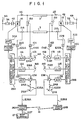
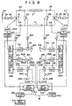
- Fig. 1 shows a prior art converter control system for a DC power transmission line.
- Such a control system is generally known from the following publication:
- EP-A-O 087 640 A similar control system is disclosed in EP-A-O 087 640 (prior art according to Art. 54(3) EPC).
- Fig. 1 Details of each element shown in Fig. 1 are known to a skilled person in the art.
- the DC circuit of a converter 1A is coupled via a DC reactor 2A, DC power transmission lines 3 and a DC reactor 2B to the DC circuit of a converter 1B.
- the AC circuit of converter 1A is coupled via a converter transformer 4A and a circuit breaker 5A to a 3-phase AC power line 6A
- the AC circuit of converter 1B is coupled via a converter transformer 4B and a circuit breaker 5B to a 3-phase AC power line 6B.
- Converter 1A is associated with an automatic voltage regulator 11A, an automatic extinction angle regulator 12A and an automatic current regulator 13A.
- Converter 1B is associated with an automatic voltage regulator 11B, an automatic extinction angle regulator 12B and an automatic current regulator 13B.
- Automatic extinction angle regulator 12A is provided for a prescribed operation that the extinction angle of converter 1A traces or follows a reference extinction angle value E18A obtained from a extinction angle presetter 18A
- automatic extinction angle regulator 12B is provided for a prescribed operation that the extinction angle of converter 1B follows a reference extinction angle value E18B obtained from a extinction angle presetter 18B.
- the value of a detected DC voltage obtained from a DC voltage detector 15A is properly changed via a voltage/voltage converter 16A to a value being well adapted to the control circuitry of Fig. 1.
- the changed value obtained from voltage/ voltage converter 16A is used as a DC voltage detected value E16A.
- DC voltage detected value E16A is subtracted in a summing circuit 17A from a reference voltage value E14A obtained from a DC voltage presetter 14A.
- Summing circuit 17A supplies to automatic voltage regulator 11A the difference between DC voltage detected value E16A and reference voltage value E14A, so that the DC voltage of DC power transmission line 3 at converter 1A side follows the reference voltage value E14A from DC voltage presetter 14A.
- the value of a detected DC voltage obtained from a DC voltage detector 15B is properly changed via a voltage/voltage converter 168 to a value being well adapted to the control circuitry of Fig. 1.
- the changed value obtained from voltage/ voltage converter 16B is used as a DC voltage detected value E16B.
- DC voltage detected value E16B is subtracted in a summing circuit 17B from a reference voltage value E14B obtained from a DC voltage presetter 14B.
- Summing circuit 178 supplies to automatic voltage regulator 11B the difference between DC voltage detected value E16B and reference voltage value E14B, so that the DC voltage of DC power transmission line 3 at converter 1B side follows the reference voltage value E14B from DC voltage presetter 14B.
- the detected DC current value obtained from a DC current detector 21A is converted via a current/voltage converter 22A to a value being well adapted to the control circuitry.
- the converted value obtained from current/voltage converter 22A is used as a DC current detected value E22A.
- DC current detected value E22A is subtracted in a summing circuit 23A from a reference current value E26A obtained from a transmission control circuit 26A.
- Summing circuit 23A supplies to automatic current regulator 13A the difference between DC current detected value E22A and reference current value E26A, so that the DC current of DC power transmission line 3 at converter 1A side follows the reference current value E26A from transmission control circuit 26A.
- the detected DC current value obtained from a DC current detector 21B is converted via a current/ voltage converter 22B to a value being well adapted to the control circuitry.
- the converted value obtained from current/voltage converter 22B is used as a DC current detected value E22B.
- DC current detected value E22B is subtracted in a summing circuit 23B from a reference current value E26B obtained from a transmission control circuit 26B.
- Summing circuit 23B supplies to automatic current regulator 13B the difference between DC current detected value E22B and reference current value E26B, so that the DC current of DC power transmission line 3 at converter 1B side follows the reference current value E26B from transmission control circuit 26B.
- a current margin value E25A or E25B obtained from a current margin presetter 25A or 25B is supplied via the closed one of switches 24A and 24B to the corresponding summing circuit 23A or 23B. Of switches 24A and 24B, only the one which allows the corresponding converter to operate as an inverter is closed.
- An advanced control angle preference circuit 28A receives outputs from regulators 11A, 12A and 13A. Advanced control angle preference circuit 28A selects only one of the received outputs in a manner that the selected one has the most phase-advanced control angle.
- An advanced control angle preference circuit 28B receives outputs from regulators 11B, 12B and 13B, and selects only one having the most phase-advanced control angle.
- circuit 28A selects the output from automatic current regulator 13A and circuit 28B selects one having the most phase-advanced control angle of outputs from automatic voltage regulator 11B and automatic extinction angle regulator 12B.
- Circuit 28B generally selects the output from automatic voltage regulator 11B.
- the selected output from circuit 28A is supplied to a phase control circuit 29A in which the selected output is converted into pulse signals which determine the triggering timing of the corresponding converter 1A.
- the selected output from circuit 28B is supplied to a phase control circuit 29B in which the selected output is converted into pulse signals which determine the triggering timing of the corresponding converter 1B.
- the pulse signals from phase control circuit 29A are supplied as gate pulses to converter 1A via a pulse amplifier 30A.
- the pulse signals from phase control circuit 29B are supplied as gate pulses to converter 1 B via a pulse amplifier 30B.
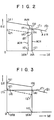
- a converter control system It is conventional to arrange a converter control system in the manner described above. It is also known from, e.g., Japanese Patent Publication (Kokoku) No. 46-33255 that a typical operation characteristic curve of DC power transmission utilized in such a converter control system becomes as shown in Fig.2.
- Fig. 2 a DC current Id is plotted along the axis of abscissa and a DC voltage Ed is plotted along the axis of ordinate. Since it has been assumed that switch 24A is opened and switch 24B is closed, converter 1A serves as a rectifier (forward converter) while converter 1B serves as an inverter (reverse converter). The following description will be made under this assumption.
- a curve having portions (a), (b) and (c) in Fig. 2 represents the characteristic of converter 1A which operates as a rectifier.
- a curve having portions (d), (e), (f) and (g) shows the characteristic of converter 1B which operates as an inverter.
- the intersecting point of the curve of (a) to (c) and the curve of (d) to (g) defines the operational point of the DC power transmission line.
- portions (a), (b) and (c) represents the regulation curve which depends mainly on the commutating impedance of converter 1A.
- Portions (b) and (c) represents a constant current characteristic curve obtained by the actuation of automatic current regulator 13A.
- portions (d), (e), (f) and (g) represent a constant current characteristic curve obtained by the actuation of automatic current regulator 13B.
- portions (e) and (f) represents a constant voltage characteristic curve obtained by the actuation of automatic voltage regulator 11B.
- Portions (f) and (g) represents a constant extinction angle characteristic obtained by the actuation of automatic extinction angle regulator 12B.
- the difference between a DC current IdA given by portions (b, c) and a DC current IdB given by portions (d, e) corresponds to the current margin which is generally set to be 5% to 10% of the rated DC current (IdA). For instance, if the rated current IdA is set at 10.O A, the DC current IdB is 9.0 A to 9.5 A.
- the operation characteristic curve of converter 1B may be represented by portions (h), (f) and (g) in Fig. 3.
- portions (h) and (f) represents the constant voltage characteristic obtained by the actuation of automatic voltage regulator 11B.
- Portions (f) and (g) represents to the constant extinction angle characteristic obtained by the actuation of automatic extinction angle regulator 12B.
- the operation characteristic curve of converter 1A is not changed from the case of Fig. 2, as indicated by portions (a), (b) and (c) in Fig. 3.
- An intersecting point (A) of the two operation characteristic curves defines the operation point of the DC power transmission line.
- the regulation curve is shifted from portions (a) and (b) to portions (a') and (b') as indicated by the broken line in Fig. 3.
- the operation characteristic curve of converter 1A becomes one being represented by the portions (a'), (b') and (c) in Fig. 3.
- the operation point of the DC power transmission line is shifted from point (A) to a point (A') of Fig. 3. In this case, only a little DC current can flow and the power transfer from AC line 6A to AC line 6B is substantially disenabled. This is a serious problem.
- the current margin is generally set at 5% to 10% of the rated current (IdA).
- the operation characteristic curve of converter 1B becomes one being represented by portions (d), (e), (f) and (g) in Fig. 2.
- the operation point of DC power transmission line is changed only from point (A) to a point (A') of Fig. 2.
- a DC power transmission line is generally provided with a control circuit for controlling the amount of power transfer between AC line 6A and AC line 6B.
- This control circuit produces a reference current value which corresponds to a current flowing through the power transmission line.
- the reference current value is supplied to the forward and reverse converters.
- the circuit for controlling the power transfer is called as a reference current output circuit 27.
- An output signal E27 from reference current output circuit 27 is constantly supplied to transmission control circuit 26A and supplied, via a transmission line 19 of a communication system such as a microwave communication line, to transmission control circuit 26B.
- the constant current characteristic portion (IdB in Fig. 2) of the reverse converter (inverter) is set to be smaller than that (IdA in Fig. 2) of the forward converter (rectifier) by a value corresponding to current margin value E25A or E25B. More specifically, current margin value E25A or E25B is supplied to summing circuit 23A or 238 by proper selection of switches 24A and 24B, and the converter responsive to the selected current margin value operates as a reverse converter.
- converter 1B when switch 24B is closed while switch 24A is opened and if reference current value E26A of converter 1A is equal to reference current value E26B of converter 1B, converter 1B operates as a reverse converter and has an operation characteristic curve of portions (d) to (g) as shown in Fig. 2. This characteristic curve is obtained by the function of the current margin and by the function of advanced control angle preference circuits 28A and 28B.
- reference current value E26B of converter 1B becomes larger by a value in excess of current margin E25B than reference current value E26A of converter 1A.
- current IdB of the constant current characteristic portion of converter 1B becomes higher than current IdA of the constant current characteristic portion of converter 1A.
- This situation is equivalent to a state wherein, if reference current value E26B of converter 1B is apparently equal to reference current value E26A of converter 1A, the difference between current IdB and current IdA is supplied to converter 1A as a signal corresponding to the current margin.
- control mode is changed from one in which converter 1A operates as a forward converter while converter 1B operates as a reverse converter to one in which converter 1A operates as a reverse converter while converter 1B operates as a forward converter.
- Such a control mode change is called "power reversal".
- power reversal When a power reversal occurs, the power transfer from AC line 6A to AC line 6B is stopped, but that from AC line 68 to AC line 6A is carried out. This is a serious problem of the prior art converter control system.
- transmission control circuits 26A and 26B In a prior art converter control system, in order to solve the above power reversal problem, transmission control circuits 26A and 26B must have not only the signal transfer function as described above but also have the following function. That is, when output signal E27 from reference current output circuit 27 decreases, the reference current value of a converter to be operated as a reverse converter is decreased first and then the reference current value of a converter to be operated as a forward converter is decreased. Conversely, when output signal E27 from reference current output circuit 27 increases, the reference current value of a converter to be operated as a forward converter is increased first and then the reference current value of a converter to be operated as a reverse converter is increased.
- transmission control circuits 26A and 26B transfer or exchange their given signals in a manner that the reference current value of a converter to be operated as a forward converter is always kept larger than that of a converter to be operated as a reverse converter.
- transmission control circuits 26A and 26B of the prior art system serve to transfer their signals so that a necessary current margin is always retained regardless of the increase or decrease of output signal E27 from reference current output circuit 27.
- the reverse converter should have a specific constant current characteristic whose constant current value is determined by subtracting the current margin of 5% to 10% from the constant current value of the forward converter.
- the current margin value must be maintained at a certain value.
- the reference current value determining the amount of power transfer cannot be properly changed. This would cause a disadvantageous situation that, even if output signal E27 from reference current output circuit 27 changes, transmission line 19 of the communication system cannot transmit the corresponding signal change properly.
- the reference current value of a converter to be operated as a reverse converter could become larger than that of a converter to be operated as a forward converter resulting in occurring said power reversal.
- the document DE-B-2 588 750 discloses a system of DC power transmission between a plurality of current regulated rectifier and inverter stations operating in parallel.
- This known prior art seeks to overcome disadvantages involved in remote control means coupling a central current command value generator to the individual stations. Instead of using such remote control means and a central current command value generator, the prior art suggests using adjustable voltage controlled command values for the-currents of the individual converter stations, such that the currents of those stations are adjusted according to their natural characteristic.
- DE-A-3 016 970 discloses a DC transmission system with a rectifying converter unit at one end and an inverting converter unit at the other end of a DC link. On their AC side both converter units are coupled to a transformer provided with a tap regulating means for adjusting a tap of the transformer such that the idle voltage of the converted voltage is held constant. With such a system problems occur due to varying voltage drops along the DC link dependent on the respective load condition. To overcome such difficulties, the prior art provides that one of the converters is subjected to a variable load current dependent DC voltage regulation. Due to this regulation, the DC terminal voltage of said one converter increases while the DC terminal voltage of the other con-verter decreases when there is only little load.
- each converter has in addition to a current controller a voltage controller that controls the DC voltage of only one of the stations whereas it is used to limit the station DC voltage in all other stations.
- the hardware implementation of this method in a voltage controlling converter station comprises two current regulators, two voltage regulators and three control angle preference circuits. These means are arranged to result in a voltage against current characteristic exhibiting a voltage change portion. The voltage change portion is achieved by means of the control angle preference circuits switching from one of the voltage regulators to the other at a minimum current value.
- the current set values are made voltage dependent resulting in a characteristic of the inverter with the voltage linearily increasing with an increase of current. This corresponds to a constant a rectifier voltage-current characteristic and a constant ⁇ inverter voltage-current characteristic with no specific control.
- a control system for converters of the invention performs a specific operation in which, when the DC current of a converter operating as a reverse converter is decreased to a value being smaller than a rated current value by a value in excess of a predetermined value, a reference voltage value which determines the DC voltage of the reverse converter is decreased and the decreased voltage value is limited to a certain extent. Then, a partial constant current characteristic portion appears at the voltage decreased portion in the voltage/ current characteristic of the reverse converter, and an automatic voltage regulator of the reverse converter is rendered always active, thereby allowing stable power transfer.
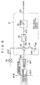
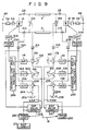
- Fig. 4 shows a schematic block diagram of a converter control system according to an embodiment of the present invention.
- the key feature of the present invention resides mainly in the configuration of a reference value correction circuit (31A, 31B).
- the common reference numerals denote the common elements having substantially the same functions, and details of the elements having already been described with reference to Figs. 1 to 3 will be omitted hereinafter.
- Reference value correction circuits 31A and 318 respectively receive reference current values E26C and E26D outputted from transmission control circuits 26C and 26D. Circuits 26C and 26D may not be necessaryily provided with a function for rendering the current margin constant, unlike the aforementioned prior art transmission control circuits 26A and 26B (Fig. 1). Reference value correction circuits 31A and 31B also receive DC current detected values E22A and E22B from current/voltage converters 22A and 22B. Descriptions regarding the reference current values E26C and E26D and those regarding the DC current detected values E22A and E22B will be described later. Reference correction values E31A and E31B obtained from reference value correction circuits 31A and 31B are respectively supplied to summing circuits 17A and 17B. Reference voltage values E14A and E14B obtained from DC voltage presetters 14A and 14B are respectively decreased by reference correction values E31A and E31B in summing circuits 17A and 17B.
- Fig. 5 shows details of each of reference value correction circuits 31A and 31B shown in Fig. 4. For the sake of simplicity, no suffices (A, B) are attached to the reference symbols.
- a summing circuit 32 in reference value correction circuit 31 receives a reference current value E26 from transmission control circuit 26, a DC current detected value E22 from current/voltage converter 22, and a predetermined bias value E35 being set by a bias presetter 35.
- Predetermined bias value E35 is supplied to summing circuit 32 via a switch 36.
- Switch 36 is closed when the corresponding converter is to be operated as a reverse converter.
- summing circuit 32 subtracts DC current detected value E22 and bias value E35 from reference current value E26 and supplies a signal E32 representing the result of the subtraction to an amplifier 33.
- Amplifier 33 amplifies the inputted signal E32 and supplies an amplified signal E33 to a limiter 34.
- Amplifier 33 serves to produce a positive signal +E33 when signal E32 is positive and serves to produce a negative signal -E33 when signal E32 is negative.
- limiter 34 has a function to limit the potential of its output which is used as reference correction value E31, so that output E31 does not become negate when signal E33 is negative and so that output E31 will not exceed a predetermined value (+E31P) when signal E33 is positive.
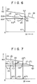
- control system having the above configuration will operate according to the characteristic curve as shown in Fig. 6. This will be described below.
- Converter 1A then operates as a forward converter (rectifier) and has an operation characteristic curve as defined by portions (a), (b) and (c) in Fig. 6. This characteristic curve is the same as that shown in Fig. 2. Meanwhile, since switch 24B is closed, current margin value E25B from current margin presetter 25B is supplied to summing circuit 23B.
- converter 1B has an operation characteristic curve being defined by portions (h), (f) and (g) as shown in Fig. 3.
- reference value correction circuit 31B for converter 1B will now be described with reference to Figs. 4 and 5, wherein switch 36 (Fig. 5) of reference value correction circuit 31B (Fig. 4) is closed.
- bias value E35 (Fig. 5) is set by bias presetter 35 to be 5% to 10% of the rated DC current value, as in the case for the current margin of a prior art converter control system (Fig. 1).
- reference current value E26 (E26D in Fig. 4) from transmission control circuit 26 and DC current detected value E22 (E22B in Fig. 4) from current/voltage converter 22 are inputted to summing circuit 32 of reference value correction circuit 31 (31B in Fig. 4).
- the former reference current value (E26) is normally equal to the latter DC current detected value (E22).
- amplifier 33 (Fig. 5) receives signal E32 having a negative potential corresponding to bias value E35. Therefore, output E33 from amplifier 33 becomes negative.
- converter 1B (Fig. 4) operates under a constant voltage control according to reference voltage value E14B from DC voltage presetter 14B. In this case, a constant voltage EdX (Fig. 6) corresponding to reference voltage value E14B is obtained at the DC circuit of converter 1B.
- the operation characteristic curve of converter 1B becomes one having portions (i), (j), (k), (f) and (g) as shown in Fig. 6.
- the DC power transmission line operates at point (A).
- Point (A) is defined by the intersection of the operation characteristic curves having portions (a), (b) and (c) of converter 1A (forward converter) and that having portions (i), (j), (k), (f) and (g) of converter 1B (reverse converter).
- the operation point of the DC power transmission line according to the present embodiment remains the same as point (A) in Fig. 2.
- transmission control circuits 26A and 26B of the prior art control system must have a function for maintaining a constant current margin. However, in the control system of the present invention, such a maintaining function need not be incorporated. It is sufficient to the present invention that an output signal E27 from reference current output circuit 27 is properly transmitted, received and memorized. As was described with reference to transmission control circuits 26A and 26B in Fig. 1, in order to constantly maintain a certain current margin, reference current values E26A and E26B are generally memorized in transmission control circuits 26A and 26B when reference current values E26A and E26B are supplied to summing circuits 23A and 23B. For the sake of simplicity, it is also assumed in the present invention that reference current values E26C and E26D are memorized in transmission control circuits 26C and 26D (cf. 26 in Fig. 5).
- transmission control circuits 26C and 26D respectively memorize the reference current values corresponding to the DC current at portions (b) and (c) in Fig. 7.
- reference current value E26C of converter 1A When output E27 from reference current output circuit 27 decreases, reference current value E26C of converter 1A also decreases. Then, the operation characteristic curve of converter 1A is shifted from one having portions (a), (b) and (c) to one having portions (a), (b') and (c') as indicated by the broken line in Fig. 7.
- reference value correction circuit 31B serves to decrease the DC voltage of converter 1B.
- the operation characteristic curve of converter 1B becomes one having portions (i), (j), (k), (f) and (g) which is the same as that obtained before failure of the communication system.
- an operating point (C) which is defined at the intersection of portions (b'), (c') and portions (i), (j) in Fig. 7 is obtained.
- each of transmission control circuits 26C and 26D is provided with a means for memorizing the reference current values E26C and E26D. If transmission control circuits 26C and 26D are not provided with such a means, reference current value E26D of converter 1B disappears when the communication system of transmission line 19 fails. When such failure occurs, the operation characteristic curve of converter 1B becomes one having portions (i''), (k), (f) and (g) as shown in Fig. 7, which is the same as that having portions (h), (f) and (g) in Fig. 3. Thus, even if the abovementioned memorizing means is not provided, unless the AC voltage at the forward converter side decreases substantially, stable power transfer can be performed.
- the control system of the invention is further provided with a means for detecting a failure of the communication system and also with a means for setting the reference current value of a reverse converter to be larger than the rated DC current, the resultant operation characteristic curve becomes one having portions (i), (j), (f') and (g) as shown in Fig. 7.
- the operation characteristic curve of Fig. 7 stable power transfer can be performed, provided that decrease in the AC voltage of the forward converter is not so large.
- reference correction values E31A and E31B from reference value correction circuits 31A and 31B are respectively supplied to summing circuits 17A and 17B so as to decrease reference voltage values E17A and E17B of automatic voltage regulators 11A and 11B.
- the decreased amount of each of reference voltage values E17A and E17B is limited to a predetermined value according to the operation of limiter 34 shown in Fig. 5.
- reference correction values E31A and E31B from reference value correction circuits 31A and 31B may be respectively added in summing circuits 80A and 80B to reference extinction angle values E18A and E18B from extinction angle presetters 18A and 18B.
- Summing circuits 80A and 80B supply the added results E80A and E80B to automatic extinction angle regulators 12A and 12B, respectively.
- the extinction angle values of converters 1A and 1B are also increased. Then, the DC voltages of converters 1A and 1B are decreased.
- similar operations as that described with reference to the embodiment of Fig. 4 can be obtained.
- automatic voltage regulators 11A and 11B can be omitted, as the case may be.
- Fig. 9 The configuration of the embodiments of Figs. 4 and 8 may be combined as shown in Fig. 9.
- reference correction value E31A of converter 1A is supplied to summing circuits 17A and 80A
- reference correction value E31B of converter 1B is supplied to summing circuits 17B and 80B.
- the reference voltage value (E17B) for the automatic voltage regulator (11B) is decreased (Fig. 4 embodiment).
- the reference extinction angle value (E80B) for the extinction angle regulator (12B) may be increased so as to decrease the DC voltage at the reverse converter side (Fig. 8 embodiment).
- the decreased value of the DC voltage is limited to a certain extent by the operation of limiter 34 (Fig. 5). With this configuration, even if the AC voltage of the forward converter is decreased, stable power transfer can be effected.
Landscapes
- Engineering & Computer Science (AREA)
- Power Engineering (AREA)
- Supply And Distribution Of Alternating Current (AREA)
- Direct Current Feeding And Distribution (AREA)
- Inverter Devices (AREA)
Applications Claiming Priority (2)
| Application Number | Priority Date | Filing Date | Title |
|---|---|---|---|
| JP58111383A JPS605781A (ja) | 1983-06-21 | 1983-06-21 | 変換器の制御装置 |
| JP111383/83 | 1983-06-21 |
Publications (4)
| Publication Number | Publication Date |
|---|---|
| EP0129250A2 EP0129250A2 (en) | 1984-12-27 |
| EP0129250A3 EP0129250A3 (en) | 1986-02-12 |
| EP0129250B1 EP0129250B1 (en) | 1989-02-08 |
| EP0129250B2 true EP0129250B2 (en) | 1993-11-18 |
Family
ID=14559784
Family Applications (1)
| Application Number | Title | Priority Date | Filing Date |
|---|---|---|---|
| EP84107051A Expired - Lifetime EP0129250B2 (en) | 1983-06-21 | 1984-06-19 | Converter control system |
Country Status (5)
| Country | Link |
|---|---|
| US (1) | US4578743A (enExample) |
| EP (1) | EP0129250B2 (enExample) |
| JP (1) | JPS605781A (enExample) |
| CA (1) | CA1217809A (enExample) |
| DE (1) | DE3476728D1 (enExample) |
Families Citing this family (14)
| Publication number | Priority date | Publication date | Assignee | Title |
|---|---|---|---|---|
| JPS60207461A (ja) * | 1984-03-29 | 1985-10-19 | Toshiba Corp | 変換装置の制御装置 |
| JPS61285027A (ja) * | 1985-06-10 | 1986-12-15 | 株式会社東芝 | 交直変換装置の運転方法 |
| JPS6252617A (ja) * | 1985-08-30 | 1987-03-07 | Toshiba Corp | 調相設備の制御装置 |
| JP2507387B2 (ja) * | 1987-02-13 | 1996-06-12 | 株式会社東芝 | 電力変換装置 |
| US4884181A (en) * | 1987-08-26 | 1989-11-28 | Siemens Aktiengesellschaft | Method and arrangement for controlling a high voltage d-c transmission system |
| EP0482002B1 (de) * | 1989-07-11 | 1993-09-01 | Siemens Aktiengesellschaft | Verfahren und vorrichtung zur ablösenden regelung mehrerer regelgrössen eines stromrichters |
| JPH04355628A (ja) * | 1991-05-31 | 1992-12-09 | Toshiba Corp | 直流送電線路短絡検出装置 |
| DE4420600C1 (de) * | 1994-06-13 | 1995-11-16 | Siemens Ag | Verfahren und Anordnung zur Gleichstromübertragung |
| SE9403486L (sv) * | 1994-10-13 | 1996-04-14 | Asea Brown Boveri | Förfarande och anordning för styrning av en anläggning för överföring av högspänd likström |
| JP3311214B2 (ja) * | 1995-09-05 | 2002-08-05 | 東京電力株式会社 | 電力変換装置の制御装置 |
| GB2419043A (en) * | 2004-09-27 | 2006-04-12 | Areva T & D Uk Ltd | DC transmission system with variable current and voltage |
| CN103257589B (zh) * | 2013-03-29 | 2015-12-23 | 国家电网公司 | 一种电压调节器仿真装置 |
| CN104518519B (zh) * | 2013-09-26 | 2017-11-03 | 南京南瑞继保电气有限公司 | 直流电压控制方法及装置 |
| WO2017158891A1 (ja) * | 2016-03-15 | 2017-09-21 | 三菱電機株式会社 | 電力変換装置および電力システム |
Family Cites Families (7)
| Publication number | Priority date | Publication date | Assignee | Title |
|---|---|---|---|---|
| DE1588750B2 (de) * | 1967-08-16 | 1971-04-29 | Siemens AG, 1000 Berlin u 8000 München | Verfahren und einrichtung zur uebertragung von gleichstrom |
| DE2901263C2 (de) * | 1979-01-13 | 1985-05-23 | Brown, Boveri & Cie Ag, 6800 Mannheim | Regelung einer HGÜ-(Hochspannungs-Gleichstrom- Übertragungs-)-Kurzkupplung |
| JPS55147920A (en) * | 1979-05-04 | 1980-11-18 | Hitachi Ltd | Dc transmission device operation control system |
| JPS58148625A (ja) * | 1982-02-26 | 1983-09-03 | 株式会社東芝 | 変換器の制御装置 |
| JPS59103520A (ja) * | 1982-12-03 | 1984-06-15 | 財団法人 電力中央研究所 | 変換所並列方式直流多端子系の電力潮流制御方式 |
| JPS6416092A (en) * | 1987-07-09 | 1989-01-19 | Matsushita Electric Industrial Co Ltd | Optical unit for video camera |
| JPH0825597B2 (ja) * | 1987-08-14 | 1996-03-13 | 株式会社タツノ・メカトロニクス | 給油装置の漏油検知方法 |
-
1983
- 1983-06-21 JP JP58111383A patent/JPS605781A/ja active Granted
-
1984
- 1984-06-19 DE DE8484107051T patent/DE3476728D1/de not_active Expired
- 1984-06-19 EP EP84107051A patent/EP0129250B2/en not_active Expired - Lifetime
- 1984-06-20 CA CA000457035A patent/CA1217809A/en not_active Expired
- 1984-06-21 US US06/622,877 patent/US4578743A/en not_active Expired - Lifetime
Also Published As
| Publication number | Publication date |
|---|---|
| CA1217809A (en) | 1987-02-10 |
| JPH0570391B2 (enExample) | 1993-10-05 |
| JPS605781A (ja) | 1985-01-12 |
| EP0129250A2 (en) | 1984-12-27 |
| EP0129250B1 (en) | 1989-02-08 |
| US4578743A (en) | 1986-03-25 |
| EP0129250A3 (en) | 1986-02-12 |
| DE3476728D1 (en) | 1989-03-16 |
Similar Documents
| Publication | Publication Date | Title |
|---|---|---|
| EP0129250B2 (en) | Converter control system | |
| EP0762624B1 (en) | Control system for power converter system | |
| EP2122819B1 (en) | Method and arrangement to reverse the power flow of a direct current power transmission system | |
| EP0087640B1 (en) | Control device for a converter | |
| US4419591A (en) | Multiterminal DC power transmission system | |
| US4263517A (en) | Control method and system for an high voltage direct current system | |
| US4459492A (en) | Method for operating a high voltage direct current transmission system including any desired number of transformer stations | |
| EP0367247B1 (en) | Control apparatus of DC power coupling system | |
| EP0056659B1 (en) | Converter control apparatus for parallel connected multi-terminal direct current system | |
| JPS64899B2 (enExample) | ||
| US4106085A (en) | HVDC Floating current order system | |
| US4649466A (en) | Method and circuit arrangemeant for operating a high voltage direct current line between two alternating voltage systems | |
| US4279009A (en) | Method and regulating device for controlling high-voltage direct current transmission system | |
| US3543045A (en) | Method and apparatus for connecting and disconnecting converter station between transmission lines | |
| EP0160894B1 (en) | Control method and control apparatus for controlling a power converter | |
| JP3187667B2 (ja) | 直流送電設備の変換器制御装置 | |
| JPH05207650A (ja) | 直流送電系統制御装置 | |
| JPH0213530B2 (enExample) | ||
| SU1520625A1 (ru) | Система регулировани напр жени на промежуточной подстанции высоковольтной электропередачи | |
| JPH0332289B2 (enExample) | ||
| JP3276980B2 (ja) | 交直変換器の制御装置 | |
| JPS5848117A (ja) | 交−直変換所におけるタツプ切換制御装置 | |
| JPH0318433B2 (enExample) | ||
| SU699503A1 (ru) | Устройство дл дискретного регулировани выпр мленного напр жени | |
| JPH0126253B2 (enExample) |
Legal Events
| Date | Code | Title | Description |
|---|---|---|---|
| PUAI | Public reference made under article 153(3) epc to a published international application that has entered the european phase |
Free format text: ORIGINAL CODE: 0009012 |
|
| 17P | Request for examination filed |
Effective date: 19840619 |
|
| AK | Designated contracting states |
Designated state(s): CH DE LI SE |
|
| PUAL | Search report despatched |
Free format text: ORIGINAL CODE: 0009013 |
|
| AK | Designated contracting states |
Designated state(s): CH DE LI SE |
|
| 17Q | First examination report despatched |
Effective date: 19870915 |
|
| GRAA | (expected) grant |
Free format text: ORIGINAL CODE: 0009210 |
|
| AK | Designated contracting states |
Kind code of ref document: B1 Designated state(s): CH DE LI SE |
|
| REF | Corresponds to: |
Ref document number: 3476728 Country of ref document: DE Date of ref document: 19890316 |
|
| PLBI | Opposition filed |
Free format text: ORIGINAL CODE: 0009260 |
|
| 26 | Opposition filed |
Opponent name: SIEMENS AKTIENGESELLSCHAFT, BERLIN UND MUENCHEN Effective date: 19891108 |
|
| PUAH | Patent maintained in amended form |
Free format text: ORIGINAL CODE: 0009272 |
|
| STAA | Information on the status of an ep patent application or granted ep patent |
Free format text: STATUS: PATENT MAINTAINED AS AMENDED |
|
| 27A | Patent maintained in amended form |
Effective date: 19931118 |
|
| AK | Designated contracting states |
Kind code of ref document: B2 Designated state(s): CH DE LI SE |
|
| REG | Reference to a national code |
Ref country code: CH Ref legal event code: AEN |
|
| EAL | Se: european patent in force in sweden |
Ref document number: 84107051.9 |
|
| PGFP | Annual fee paid to national office [announced via postgrant information from national office to epo] |
Ref country code: CH Payment date: 19950614 Year of fee payment: 12 |
|
| PG25 | Lapsed in a contracting state [announced via postgrant information from national office to epo] |
Ref country code: LI Effective date: 19960630 Ref country code: CH Effective date: 19960630 |
|
| REG | Reference to a national code |
Ref country code: CH Ref legal event code: PL |
|
| PGFP | Annual fee paid to national office [announced via postgrant information from national office to epo] |
Ref country code: SE Payment date: 20000606 Year of fee payment: 17 |
|
| PGFP | Annual fee paid to national office [announced via postgrant information from national office to epo] |
Ref country code: DE Payment date: 20000616 Year of fee payment: 17 |
|
| PG25 | Lapsed in a contracting state [announced via postgrant information from national office to epo] |
Ref country code: SE Free format text: LAPSE BECAUSE OF NON-PAYMENT OF DUE FEES Effective date: 20010620 |
|
| EUG | Se: european patent has lapsed |
Ref document number: 84107051.9 |
|
| PG25 | Lapsed in a contracting state [announced via postgrant information from national office to epo] |
Ref country code: DE Free format text: LAPSE BECAUSE OF NON-PAYMENT OF DUE FEES Effective date: 20020403 |