EP0129232B1 - Capteur d'impulsions électromagnétiques pour débitmètre - Google Patents
Capteur d'impulsions électromagnétiques pour débitmètre Download PDFInfo
- Publication number
- EP0129232B1 EP0129232B1 EP84106925A EP84106925A EP0129232B1 EP 0129232 B1 EP0129232 B1 EP 0129232B1 EP 84106925 A EP84106925 A EP 84106925A EP 84106925 A EP84106925 A EP 84106925A EP 0129232 B1 EP0129232 B1 EP 0129232B1
- Authority
- EP
- European Patent Office
- Prior art keywords
- cylinder
- pickup
- wiegand
- measuring
- measuring wheel
- Prior art date
- Legal status (The legal status is an assumption and is not a legal conclusion. Google has not performed a legal analysis and makes no representation as to the accuracy of the status listed.)
- Expired
Links
- 238000005259 measurement Methods 0.000 claims description 4
- 238000007789 sealing Methods 0.000 claims description 4
- 238000005266 casting Methods 0.000 claims 1
- 239000004020 conductor Substances 0.000 abstract 1
- 238000005192 partition Methods 0.000 description 3
- 238000009434 installation Methods 0.000 description 2
- 238000006798 ring closing metathesis reaction Methods 0.000 description 2
- 230000004308 accommodation Effects 0.000 description 1
- 230000002411 adverse Effects 0.000 description 1
- 238000013016 damping Methods 0.000 description 1
- 238000005538 encapsulation Methods 0.000 description 1
Images
Classifications
-
- G—PHYSICS
- G01—MEASURING; TESTING
- G01F—MEASURING VOLUME, VOLUME FLOW, MASS FLOW OR LIQUID LEVEL; METERING BY VOLUME
- G01F3/00—Measuring the volume flow of fluids or fluent solid material wherein the fluid passes through the meter in successive and more or less isolated quantities, the meter being driven by the flow
- G01F3/02—Measuring the volume flow of fluids or fluent solid material wherein the fluid passes through the meter in successive and more or less isolated quantities, the meter being driven by the flow with measuring chambers which expand or contract during measurement
- G01F3/04—Measuring the volume flow of fluids or fluent solid material wherein the fluid passes through the meter in successive and more or less isolated quantities, the meter being driven by the flow with measuring chambers which expand or contract during measurement having rigid movable walls
- G01F3/06—Measuring the volume flow of fluids or fluent solid material wherein the fluid passes through the meter in successive and more or less isolated quantities, the meter being driven by the flow with measuring chambers which expand or contract during measurement having rigid movable walls comprising members rotating in a fluid-tight or substantially fluid-tight manner in a housing
-
- G—PHYSICS
- G01—MEASURING; TESTING
- G01F—MEASURING VOLUME, VOLUME FLOW, MASS FLOW OR LIQUID LEVEL; METERING BY VOLUME
- G01F15/00—Details of, or accessories for, apparatus of groups G01F1/00 - G01F13/00 insofar as such details or appliances are not adapted to particular types of such apparatus
- G01F15/06—Indicating or recording devices
-
- G—PHYSICS
- G01—MEASURING; TESTING
- G01P—MEASURING LINEAR OR ANGULAR SPEED, ACCELERATION, DECELERATION, OR SHOCK; INDICATING PRESENCE, ABSENCE, OR DIRECTION, OF MOVEMENT
- G01P3/00—Measuring linear or angular speed; Measuring differences of linear or angular speeds
- G01P3/42—Devices characterised by the use of electric or magnetic means
- G01P3/44—Devices characterised by the use of electric or magnetic means for measuring angular speed
- G01P3/48—Devices characterised by the use of electric or magnetic means for measuring angular speed by measuring frequency of generated current or voltage
- G01P3/481—Devices characterised by the use of electric or magnetic means for measuring angular speed by measuring frequency of generated current or voltage of pulse signals
- G01P3/4815—Devices characterised by the use of electric or magnetic means for measuring angular speed by measuring frequency of generated current or voltage of pulse signals using a pulse wire sensor, e.g. Wiegand wire
Definitions
- the invention relates to an electromagnetic pickup for flow meters, in particular of small nominal size, in which a measuring wheel rotating in the measuring chamber carries a magnetic device with pole faces directed towards a measuring chamber end wall and a «Wiegand» sensor is fixedly arranged in the adjacent space outside the magnetically non-conductive measuring chamber end wall is, with each revolution of the measuring wheel magnetic pulses are generated which generate electrical voltage pulses in a pickup coil, the number of which is a measure of the measuring medium flowing through the flow meter.
- Such a pickup is known from DE-OS 30 46 804, which shows a "Wiegand” sensor for impeller counters in the dry-rotor design, in which a ring magnet inserted into the hub of the impeller and rotating with the impeller is on a single, outside a partition located "Wiegand” wire, which is wound by a coil and which is transverse to the impeller axis and crosses this axis.
- the disadvantage here is that only one pulse is emitted with each measurement wheel revolution, so that the measurement value resolution is only very low.
- this additional scanning drum also represents a large circulating mass which brakes the circulation.
- the sudden change in polarity of the Wiegand wires must be transmitted to the stationary coil over a relatively large distance through the flow meter housing jacket, as a result of which only relatively weak pulses result.
- additional damping of the Wiegand pulse takes place. This pickup is unsuitable for installation in flowmeters with a small nominal diameter, because the additional scanning drum, which carries the Wiegand wires, becomes much too large in relation to the measuring wheel and would therefore make a compact meter design impossible.
- the object of the invention is to design a Wiegand sensor as a pulse pickup for flow meters, in particular of small nominal size, in such a way that it can be installed in a simple manner and with the least structural changes that do not adversely affect the measurement properties in tried and tested flow meters of compact design and a high pulse resolution with strong Single pulses guaranteed.
- the Wiegand wires are parallel to the axis of rotation of the measuring wheel and rest on a pole ring on the side facing away from the measuring wheel, the main part of the field lines of the magnetic field formed between the pole faces of the individual magnets now runs from the pole face of the one magnet through the partition and then along the Wiegand wires lying in the effective area of this magnet continue to the pole ring, in which they reach the effective area of the other magnet by ring closure, so that the field lines here along the Wiegand wires lying in the effective area of this magnet enter the pole face of the other magnet through the partition wall .
- the Wiegand wires Due to this axial extension of the magnetic field over the pole ring, the Wiegand wires are acted upon by the magnetic field over a much greater length than would be the case without the pole ring, since the field lines then seek the path with the least resistance through the magnetically non-conductive space between the two magnets would.
- the magnetic application of a much larger Wiegand wire section generates a high magnetic pulse in the Wiegand wires, which generates a high signal voltage in the pick-up coil arranged in the immediate vicinity of the Wiegand wires.
- a structurally simple arrangement of Wiegand wires and pick-up coil results from the features of claim 2, the diameter of the pick-up coil lying on the one hand directly inside the circular cylinder formed by the Wiegand wires of the pickup cylinder can be kept small with maximum utilization of the outer surface in relation to the number of Wiegand wires to be accommodated, and on the other hand the pickup coil comes to rest in the immediate area of action of the Wiegand wires.
- the Wiegand wires are held in a simple manner in the longitudinal grooves of the take-up cylinder in that they are clamped, glued or potted with the take-up spool in accordance with claim 3.
- the Wiegand wires according to the features of claim 4 extend to the magnet-side end face of the sensor cylinder, which is inserted into a cylinder recess of the measuring chamber end wall to the thin-walled bottom, the Wiegand wires are brought as close as possible to the two individual magnets, whereby Adequate magnetic exposure to the Wiegand wires is achieved even when using small individual magnets. In particular with small meter sizes, there is often no space available for installing larger magnets in the measuring wheel, so that even this smallest measuring wheel can be reliably scanned only through this design.
- the pick-up coil according to the features of claim 5 is brought close to the magnet-side end face of the pick-up cylinder and the pole ring on the opposite side is pushed onto the outer jacket of the pick-up cylinder in such a way that it only closely covers the outer area of the Wiegand wires, this will be between the magnetic ring forming the pole ring and the individual magnet is particularly strongly concentrated in the longitudinal direction on the Wiegand wires, so that strong magnetic individual pulses are generated.
- the pole ring also forms a holder for the Wiegand wires lying in the longitudinal grooves of the cylinder jacket and can be used as an assembly aid for the Wiegand wires.
- the pick-up cylinder, together with the Wiegand wires, the pick-up coil and the pole ring forms a compact unit that can be easily inserted into the cylinder recess of the end wall of the measuring chamber.
- the flow meters equipped with the pulse pickup are not subject to any restrictions with regard to the flow media to be used, so that the pulse pickup can also be used with highly aggressive media.
- the pulse pick-up according to the invention emits a number of simultaneous individual pulses even with oval wheel counters in which the measuring wheel carrying the two individual magnets rotates non-uniformly, or generates a constant frequency within each revolution of the measuring wheel with constant flow
- it is proposed according to claim 7 apply the Wiegand wires to the outer jacket of the transducer cylinder with an uneven pitch that compensates for the uneven rotation of the measuring wheel. This is particularly important in the case of flow measuring systems in which the emitted pulses are used for control purposes and for this a sufficiently high frequency, which is also constant within a measuring wheel revolution, is required.
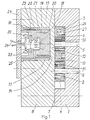
- the oval gear meter of small nominal size shown in FIGS. 1 to 3 consists of the meter housing 1 with the measuring chamber 2, in which the two oval gears 3 and 4 rotate on their axes 5 and 6.
- the measuring chamber 2 is closed on its open end face 7 by the housing cover 8, which forms the measuring chamber end wall and is provided in the region of the oval wheel 3 carrying the individual magnets 9 and 10 with a cylinder recess 11 into which the pick-up cylinder 12 is inserted.
- the axis 13 of the cylinder recess 11 and the transducer cylinder 12 is aligned with the axis 5 of the oval wheel 3 and the cylinder recess 11 is screwed so deep into the housing cover 8 that between the end face 14 of the transducer cylinder 12 and the end face 7 of the measuring chamber 2 only one taking into account the greatly enlarged scale, relatively thin-walled floor 15 remains.
- the two individual magnets 9 and 10 lie in the outer region of the large oval axis of the oval wheel 3 and the pick-up cylinder 12 is chosen so large in diameter that its outer jacket 16 lies in the effective range of these two individual magnets 9 and 10.
- the pickup cylinder 12 is provided on its side facing the two magnets 9 and 10 with an annular groove 17 into which the pickup coil 18 is inserted. Between the end face 14 of the pick-up cylinder 12 and the annular groove 17, only a thin side web 19 is left, which carries the longitudinal grooves 20 on its outer jacket for the Wiegand wires 21 held therein. On the other side of the annular groove 17, the outer longitudinal grooves 22 are provided for holding the outer regions of the Wiegand wires in the sensor cylinder 12.
- the pole ring 23 On the outer side of the pick-up cylinder 12, the pole ring 23 is pushed closely over the end region of the Wiegand wires 21, which together with the Wiegand wires 21 and the pick-up coil 18 forms an insertable unit with the pick-up cylinder 12. This in the cylinder The recess 11 inserted module is closed to the outside by the screwed-on cover plate 24 and sealed by the sealing ring 25.
- the individual magnets 9 and 10 are each inserted into a blind bore 26 of the oval wheel 3, which extends into the vicinity of the end 7 of the measuring chamber.
- the two blind bores 26 are closed by sealing plugs 27.
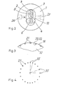
- the Wiegand wires 21 are applied with an uneven pitch on the outer jacket of the pickup cylinder, so that the uneven rotation of the oval wheels 3 and 4 can be compensated.
- the angle between the individual radii 35 changes twice between a minimum value and a maximum value in accordance with the degree of non-uniformity of the oval wheels during one revolution.
Landscapes
- Physics & Mathematics (AREA)
- General Physics & Mathematics (AREA)
- Fluid Mechanics (AREA)
- Measuring Volume Flow (AREA)
- Measuring Pulse, Heart Rate, Blood Pressure Or Blood Flow (AREA)
Claims (7)
Priority Applications (1)
| Application Number | Priority Date | Filing Date | Title |
|---|---|---|---|
| AT84106925T ATE41516T1 (de) | 1983-06-18 | 1984-06-16 | Elektromagnetischer impulsaufnehmer fuer durchflussmesser. |
Applications Claiming Priority (2)
| Application Number | Priority Date | Filing Date | Title |
|---|---|---|---|
| DE3321952A DE3321952C2 (de) | 1983-06-18 | 1983-06-18 | Elektromagnetischer Impulsaufnehmer für Durchflußmesser |
| DE3321952 | 1983-06-18 |
Publications (3)
| Publication Number | Publication Date |
|---|---|
| EP0129232A2 EP0129232A2 (fr) | 1984-12-27 |
| EP0129232A3 EP0129232A3 (en) | 1986-01-02 |
| EP0129232B1 true EP0129232B1 (fr) | 1989-03-15 |
Family
ID=6201747
Family Applications (1)
| Application Number | Title | Priority Date | Filing Date |
|---|---|---|---|
| EP84106925A Expired EP0129232B1 (fr) | 1983-06-18 | 1984-06-16 | Capteur d'impulsions électromagnétiques pour débitmètre |
Country Status (4)
| Country | Link |
|---|---|
| US (1) | US4579008A (fr) |
| EP (1) | EP0129232B1 (fr) |
| AT (1) | ATE41516T1 (fr) |
| DE (1) | DE3321952C2 (fr) |
Cited By (2)
| Publication number | Priority date | Publication date | Assignee | Title |
|---|---|---|---|---|
| DE202017106253U1 (de) | 2017-10-16 | 2019-01-17 | Flaco-Geräte GmbH | Ovalzahnrad |
| DE202017106254U1 (de) | 2017-10-16 | 2019-01-17 | Flaco-Geräte GmbH | Durchflussmessgerät |
Families Citing this family (34)
| Publication number | Priority date | Publication date | Assignee | Title |
|---|---|---|---|---|
| DE3511537A1 (de) * | 1985-03-29 | 1986-10-09 | Elco Oel- und Gasbrennerwerk AG, Vilters | Einrichtung zur bestimmung des oelverbrauchs eines oelbrenners |
| US4641522A (en) * | 1985-04-03 | 1987-02-10 | Lopresti William J | Bearing-less positive displacement flowmeter |
| DE3538514A1 (de) * | 1985-10-30 | 1987-05-07 | Bopp & Reuther Gmbh | Elektromagnetischer impulsaufnehmer fuer durchflussmesser |
| US4911010A (en) * | 1988-08-12 | 1990-03-27 | Flowdata, Inc. | Fluid flowmeter |
| DE3918925A1 (de) * | 1989-06-09 | 1990-12-13 | Joseph Voegele Ag | Vorrichtung zum zuteilen von schmierstoff |
| US4996888A (en) * | 1989-08-09 | 1991-03-05 | Flowdata, Inc. | Fluid flowmeter |
| US5325715A (en) * | 1989-08-09 | 1994-07-05 | Flowdata, Inc. | Fluid flowmeter |
| DE3932735A1 (de) * | 1989-09-30 | 1991-04-18 | Dotronic Mikroprozessortechnik | Vorrichtung zum erfassen der durchflussmengen bei gaszaehlern |
| US5027653A (en) * | 1990-06-22 | 1991-07-02 | Foran Jr Charles D | Flowmeters having rotors with grooved bores and lands |
| DE4040409C1 (fr) * | 1990-12-18 | 1992-05-14 | Vse Schweisstechnik Gmbh, 5982 Neuenrade, De | |
| US5251785A (en) * | 1992-02-06 | 1993-10-12 | The Lubrizol Corporation | Additive injection system and method |
| ES2077513B1 (es) * | 1993-11-15 | 1997-10-16 | Tremino Gomez J | Medidor volumetrico de desplazamiento positivo. |
| DE19505172A1 (de) * | 1995-02-16 | 1996-08-22 | Elster Produktion Gmbh | Drehkolbenzähler zur Volumenmessung eines Fluides |
| DE19714351C2 (de) * | 1997-03-26 | 1999-01-28 | Rmg Gaselan Regel & Mestechnik | Verfahren und Vorrichtung zum Erfassen von Gas- und Flüssigkeitsvolumina mit Volumenzählern |
| US6060926A (en) * | 1998-02-01 | 2000-05-09 | American Meter Company | Pulse conditioning circuit |
| DE29906448U1 (de) * | 1999-04-12 | 1999-08-12 | Alfons Haar Maschinenbau Gmbh & Co, 22547 Hamburg | Sensor zur berührungslosen Messung der Drehung eines Rotors in einem Flüssigkeitsdurchflußmesser |
| US6502468B1 (en) | 1999-12-27 | 2003-01-07 | Badger Meter, Inc. | Metering pulse transducer |
| CN1302114A (zh) * | 1999-12-28 | 2001-07-04 | 陈国清 | 多功能磁能动力机 |
| US6604434B1 (en) | 2000-06-23 | 2003-08-12 | Neptune Technology Group, Inc. | Method and apparatus for determining the direction and rate of a rotating element |
| AU2001287184A1 (en) * | 2000-08-17 | 2002-02-25 | Schlumberger Resource Management Services, Inc. | Batteryless electronic register |
| US6612188B2 (en) | 2001-01-03 | 2003-09-02 | Neptune Technology Group Inc. | Self-powered fluid meter |
| JP2002349507A (ja) * | 2001-05-31 | 2002-12-04 | Yasunaga Corp | アクチュエータ位置検出センサ及びこれを用いた油圧システム |
| US20040163711A1 (en) * | 2003-02-20 | 2004-08-26 | Graham Packaging Company, L.P. | Fluid regulating pinch valve |
| US7659712B2 (en) * | 2004-10-13 | 2010-02-09 | Dresser, Inc. | System and method for process measurement |
| US7498953B2 (en) * | 2004-11-16 | 2009-03-03 | Salser Jr Floyd Stanley | Smart transmitter for utility meters |
| WO2006131134A1 (fr) * | 2005-06-08 | 2006-12-14 | Ecolab Inc. | Instrument de mesure a pignon ovale |
| FI119298B (fi) * | 2006-05-12 | 2008-09-30 | Osakeyhtioe Skf Aktiebolag | Soikiohammasratasmittari |
| US20090035121A1 (en) * | 2007-07-31 | 2009-02-05 | Dresser, Inc. | Fluid Flow Modulation and Measurement |
| WO2015048652A1 (fr) * | 2013-09-30 | 2015-04-02 | Lincoln Industrial Corporation | Dispositif de mesure d'écoulement pour systèmes de lubrification |
| US9803998B1 (en) | 2013-12-31 | 2017-10-31 | Joral Llc | Absolute position sensor with fine resolution |
| US10969214B2 (en) | 2013-12-31 | 2021-04-06 | Joral Llc | Position sensor with Wiegand wire, position magnet(s) and reset magnet |
| US10768030B1 (en) * | 2019-07-10 | 2020-09-08 | United Benefit Corp. | Paddle wheel flow meter |
| US11448540B2 (en) * | 2021-01-10 | 2022-09-20 | Carlos Augusto DE ROSENZWEIG PAGES | High resolution elliptical gear flowmeter |
| CN115628790B (zh) * | 2022-09-09 | 2026-01-13 | 上海独道实业有限公司 | 直齿轮液体流量检测装置 |
Family Cites Families (7)
| Publication number | Priority date | Publication date | Assignee | Title |
|---|---|---|---|---|
| JPS54177960U (fr) * | 1978-06-02 | 1979-12-15 | ||
| DE2826609C2 (de) * | 1978-06-19 | 1986-12-11 | Robert Bosch Gmbh, 7000 Stuttgart | Einrichtung zur Abgabe von Inkrement- Impulsen und einem Triggerimpuls |
| DE2906795A1 (de) * | 1979-02-22 | 1980-09-18 | Teldix Gmbh | Impulsgeber |
| US4364011A (en) * | 1979-05-16 | 1982-12-14 | Ransome Hoffmann Pollard Ltd. | Mechanical assemblies employing sensing means for sensing motion or position |
| DE3008248A1 (de) * | 1980-02-29 | 1981-09-10 | Siemens AG, 1000 Berlin und 8000 München | Volumenzaehler |
| DE3046804C2 (de) * | 1980-12-12 | 1984-05-17 | Reiner Dipl.-Ing. 7759 Hagnau Hartig | Flügelradzähler |
| GB2074389B (en) * | 1981-01-30 | 1984-10-31 | Teldix Gmbh | Pulse generator |
-
1983
- 1983-06-18 DE DE3321952A patent/DE3321952C2/de not_active Expired
-
1984
- 1984-06-16 AT AT84106925T patent/ATE41516T1/de not_active IP Right Cessation
- 1984-06-16 EP EP84106925A patent/EP0129232B1/fr not_active Expired
- 1984-06-18 US US06/623,135 patent/US4579008A/en not_active Expired - Fee Related
Cited By (2)
| Publication number | Priority date | Publication date | Assignee | Title |
|---|---|---|---|---|
| DE202017106253U1 (de) | 2017-10-16 | 2019-01-17 | Flaco-Geräte GmbH | Ovalzahnrad |
| DE202017106254U1 (de) | 2017-10-16 | 2019-01-17 | Flaco-Geräte GmbH | Durchflussmessgerät |
Also Published As
| Publication number | Publication date |
|---|---|
| EP0129232A3 (en) | 1986-01-02 |
| EP0129232A2 (fr) | 1984-12-27 |
| US4579008A (en) | 1986-04-01 |
| ATE41516T1 (de) | 1989-04-15 |
| DE3321952A1 (de) | 1984-12-20 |
| DE3321952C2 (de) | 1985-08-22 |
Similar Documents
| Publication | Publication Date | Title |
|---|---|---|
| EP0129232B1 (fr) | Capteur d'impulsions électromagnétiques pour débitmètre | |
| EP0858585B1 (fr) | Debitmetre | |
| DE3225226C2 (fr) | ||
| DE69207049T2 (de) | Zweiteiliger Sensor mit Transformatorleistungskopplung und optischer Signalkopplung | |
| DE102006060213B4 (de) | Drehwinkelsensor | |
| EP0671008B1 (fr) | Dispositif pour mesurer des mouvements rotatifs | |
| DE2950039C2 (de) | Elektroden für elektromagnetische Durchflußmesser | |
| EP0047342A1 (fr) | Tête de mesure pour débitmètres électromagnétiques | |
| DE3519215C2 (fr) | ||
| DE69118687T2 (de) | Positionsfeststellverfahren und Vorrichtung dafür | |
| DE102016012937A1 (de) | Drehgeberanordnung | |
| DE3628585C2 (de) | Impulsdrehzahlgeber | |
| DE3600742C2 (fr) | ||
| DE69515058T2 (de) | Messwandler | |
| WO2020014724A1 (fr) | Capteurs de différence de pression pour un débitmètre ainsi que débitmètre | |
| EP0179285B1 (fr) | Débitmètre magnéto-inductif | |
| DE3022434C2 (de) | Anordnung zur Drehzahlregelung eines Wechselstrommotors | |
| DE8317704U1 (de) | Elektromagnetischer impulsaufnehmer fuer durchflussmesser | |
| DE2950213A1 (de) | Elektrischer impulsgenerator fuer einen fluessigkeitszaehler | |
| DE3401488C1 (de) | Meßsonde | |
| DE69737442T2 (de) | Massendurchflussmesser | |
| DE3435910C2 (de) | Magnetisch-induktiver Durchflußmesser mit auswechselbaren Durchflußsensoren | |
| DE3841275A1 (de) | Impulsgebereinrichtung fuer mengenzaehler | |
| DE102014106567A1 (de) | Schnellmontage | |
| DE3046804A1 (de) | Fluegelradzaehler |
Legal Events
| Date | Code | Title | Description |
|---|---|---|---|
| PUAI | Public reference made under article 153(3) epc to a published international application that has entered the european phase |
Free format text: ORIGINAL CODE: 0009012 |
|
| AK | Designated contracting states |
Designated state(s): AT BE CH FR GB IT LI NL |
|
| PUAL | Search report despatched |
Free format text: ORIGINAL CODE: 0009013 |
|
| AK | Designated contracting states |
Designated state(s): AT BE CH FR GB IT LI NL |
|
| 17P | Request for examination filed |
Effective date: 19860626 |
|
| 17Q | First examination report despatched |
Effective date: 19870827 |
|
| GRAA | (expected) grant |
Free format text: ORIGINAL CODE: 0009210 |
|
| AK | Designated contracting states |
Kind code of ref document: B1 Designated state(s): AT BE CH FR GB IT LI NL |
|
| REF | Corresponds to: |
Ref document number: 41516 Country of ref document: AT Date of ref document: 19890415 Kind code of ref document: T |
|
| ITF | It: translation for a ep patent filed | ||
| GBT | Gb: translation of ep patent filed (gb section 77(6)(a)/1977) | ||
| ET | Fr: translation filed | ||
| PLBE | No opposition filed within time limit |
Free format text: ORIGINAL CODE: 0009261 |
|
| STAA | Information on the status of an ep patent application or granted ep patent |
Free format text: STATUS: NO OPPOSITION FILED WITHIN TIME LIMIT |
|
| 26N | No opposition filed | ||
| REG | Reference to a national code |
Ref country code: CH Ref legal event code: PFA Free format text: BOPP & REUTHER AKTIENGESELLSCHAFT |
|
| NLS | Nl: assignments of ep-patents |
Owner name: BOPP & REUTHER AKTIENGESELLSCHAFT TE MANNHEIM, BON |
|
| ITTA | It: last paid annual fee | ||
| PGFP | Annual fee paid to national office [announced via postgrant information from national office to epo] |
Ref country code: BE Payment date: 19970513 Year of fee payment: 14 |
|
| PGFP | Annual fee paid to national office [announced via postgrant information from national office to epo] |
Ref country code: GB Payment date: 19970605 Year of fee payment: 14 |
|
| PGFP | Annual fee paid to national office [announced via postgrant information from national office to epo] |
Ref country code: FR Payment date: 19970625 Year of fee payment: 14 Ref country code: CH Payment date: 19970625 Year of fee payment: 14 |
|
| REG | Reference to a national code |
Ref country code: GB Ref legal event code: 746 Effective date: 19970530 |
|
| PGFP | Annual fee paid to national office [announced via postgrant information from national office to epo] |
Ref country code: NL Payment date: 19970630 Year of fee payment: 14 Ref country code: AT Payment date: 19970630 Year of fee payment: 14 |
|
| PG25 | Lapsed in a contracting state [announced via postgrant information from national office to epo] |
Ref country code: GB Free format text: LAPSE BECAUSE OF NON-PAYMENT OF DUE FEES Effective date: 19980616 Ref country code: AT Free format text: LAPSE BECAUSE OF NON-PAYMENT OF DUE FEES Effective date: 19980616 |
|
| PG25 | Lapsed in a contracting state [announced via postgrant information from national office to epo] |
Ref country code: LI Free format text: LAPSE BECAUSE OF NON-PAYMENT OF DUE FEES Effective date: 19980630 Ref country code: CH Free format text: LAPSE BECAUSE OF NON-PAYMENT OF DUE FEES Effective date: 19980630 Ref country code: BE Free format text: LAPSE BECAUSE OF NON-PAYMENT OF DUE FEES Effective date: 19980630 |
|
| BERE | Be: lapsed |
Owner name: BOPP & REUTHER G.M.B.H. Effective date: 19980630 |
|
| PG25 | Lapsed in a contracting state [announced via postgrant information from national office to epo] |
Ref country code: NL Free format text: LAPSE BECAUSE OF NON-PAYMENT OF DUE FEES Effective date: 19990101 |
|
| GBPC | Gb: european patent ceased through non-payment of renewal fee |
Effective date: 19980616 |
|
| REG | Reference to a national code |
Ref country code: CH Ref legal event code: PL |
|
| PG25 | Lapsed in a contracting state [announced via postgrant information from national office to epo] |
Ref country code: FR Free format text: LAPSE BECAUSE OF NON-PAYMENT OF DUE FEES Effective date: 19990226 |
|
| NLV4 | Nl: lapsed or anulled due to non-payment of the annual fee |
Effective date: 19990101 |
|
| REG | Reference to a national code |
Ref country code: FR Ref legal event code: ST |