EP0129146A2 - Méthode et appareil pour attacher une chaîne d'éléments de fermeture à une bande de braguette - Google Patents
Méthode et appareil pour attacher une chaîne d'éléments de fermeture à une bande de braguette Download PDFInfo
- Publication number
- EP0129146A2 EP0129146A2 EP84106441A EP84106441A EP0129146A2 EP 0129146 A2 EP0129146 A2 EP 0129146A2 EP 84106441 A EP84106441 A EP 84106441A EP 84106441 A EP84106441 A EP 84106441A EP 0129146 A2 EP0129146 A2 EP 0129146A2
- Authority
- EP
- European Patent Office
- Prior art keywords
- fly
- chain
- stack
- strip
- uppermost
- Prior art date
- Legal status (The legal status is an assumption and is not a legal conclusion. Google has not performed a legal analysis and makes no representation as to the accuracy of the status listed.)
- Granted
Links
Images


Classifications
-
- E—FIXED CONSTRUCTIONS
- E21—EARTH DRILLING; MINING
- E21C—MINING OR QUARRYING
- E21C37/00—Other methods or devices for dislodging with or without loading
- E21C37/06—Other methods or devices for dislodging with or without loading by making use of hydraulic or pneumatic pressure in a borehole
- E21C37/10—Devices with expanding elastic casings
-
- D—TEXTILES; PAPER
- D05—SEWING; EMBROIDERING; TUFTING
- D05B—SEWING
- D05B35/00—Work-feeding or -handling elements not otherwise provided for
- D05B35/06—Work-feeding or -handling elements not otherwise provided for for attaching bands, ribbons, strips, or tapes or for binding
- D05B35/064—Work-feeding or -handling elements not otherwise provided for for attaching bands, ribbons, strips, or tapes or for binding for attaching slide fasteners
-
- A—HUMAN NECESSITIES
- A41—WEARING APPAREL
- A41H—APPLIANCES OR METHODS FOR MAKING CLOTHES, e.g. FOR DRESS-MAKING OR FOR TAILORING, NOT OTHERWISE PROVIDED FOR
- A41H37/00—Machines, appliances or methods for setting fastener-elements on garments
- A41H37/06—Setting slide or glide fastener elements
-
- A—HUMAN NECESSITIES
- A44—HABERDASHERY; JEWELLERY
- A44B—BUTTONS, PINS, BUCKLES, SLIDE FASTENERS, OR THE LIKE
- A44B19/00—Slide fasteners
- A44B19/42—Making by processes not fully provided for in one other class, e.g. B21D53/50, B21F45/18, B22D17/16, B29D5/00
-
- A—HUMAN NECESSITIES
- A44—HABERDASHERY; JEWELLERY
- A44B—BUTTONS, PINS, BUCKLES, SLIDE FASTENERS, OR THE LIKE
- A44B19/00—Slide fasteners
- A44B19/42—Making by processes not fully provided for in one other class, e.g. B21D53/50, B21F45/18, B22D17/16, B29D5/00
- A44B19/58—Removing interlocking members to produce gaps
-
- A—HUMAN NECESSITIES
- A44—HABERDASHERY; JEWELLERY
- A44B—BUTTONS, PINS, BUCKLES, SLIDE FASTENERS, OR THE LIKE
- A44B19/00—Slide fasteners
- A44B19/42—Making by processes not fully provided for in one other class, e.g. B21D53/50, B21F45/18, B22D17/16, B29D5/00
- A44B19/60—Applying end stops upon stringer tapes
-
- D—TEXTILES; PAPER
- D05—SEWING; EMBROIDERING; TUFTING
- D05B—SEWING
- D05B33/00—Devices incorporated in sewing machines for supplying or removing the work
- D05B33/02—Devices incorporated in sewing machines for supplying or removing the work and connected, for synchronous operation, with the work-feeding devices of the sewing machine
-
- D—TEXTILES; PAPER
- D05—SEWING; EMBROIDERING; TUFTING
- D05D—INDEXING SCHEME ASSOCIATED WITH SUBCLASSES D05B AND D05C, RELATING TO SEWING, EMBROIDERING AND TUFTING
- D05D2303/00—Applied objects or articles
- D05D2303/20—Small textile objects e.g., labels, beltloops
Definitions
- the present invention relates to the production of trouser closures for fly openings and, more particularly, to a method of and apparatus for attaching successive fly strips to a continuous slide fastener chain.
- U.S. Patent 4,362,116 discloses an apparatus in which successive fly strips are automatically supplied to a sewing machine by means of a conveyor. However, a workman's hand is still used to place the fly strips one after another on the conveyor. Further, in the apparatus according to the U.S. Patent 4,362,116, successive fly strips are attached to a continuous slide fastener chain before element-free gaps are provided in the fastener chain. To provide the element-free gaps in the fastener chain after the successive fly strips have been attached thereto, not only retards the rate of production, but also causes the threads of the strips to be frayed or otherwise damaged during the element-free gap forming operation. This fraying of such threads impairs following peripheral operations, such as threading sliders, attaching end stops and even sewing individual prospective trouser closures to trousers.
- the present invention represents a significant advance in the art by providing a method and apparatus for full-automatically attaching successive fly strips to a continuous slide fastener chain, irrespective of the presence of element-free gaps in the fastener chain or the desired orientation of the individual fly strips with respect to the fastener chain.
- an automated assembly for sewing fly strips onto a continuous fastener chain comprises a sewing machine, a fly strip delivery system for automatically supplying successive fly strips one after another to the sewing machine, and a gap forming unit for forming element-free gaps in the chain at a uniform interval and for feeding the gapped fastener chain to the sewing machine.
- a control sensor for detecting the presence of a gap in the chain being fed to the sewing machine serves to trigger recycling of the fly strip delivery system.
- the fly strip delivery system is arranged for quick, reliable advancing of successive fly strips to the sewing machine for relatively uninterrupted fly strip attachment to a continuous chain. This is brought about by a unique system of indexed movement of successive individual fly strips obtained from a stack supply wherein, one immediately following only one step behind the other, a fly strip is: 1) withdrawn from the face of a stack and delivered flat onto a horizontal first table in a consistent manner and orientation, 2) laterally advanced from the first table and onto the upper surface of a two-tiered second table defined by transversely reciprocating, opposed upper table surface halves into the sewing station directly beneath the chain and dropped through the opening formed by the mutual retraction of the upper table surfaces onto a lower second table surface, and 3) drawn from the lower table surface into the sewing machine together with the chain for attachment with the upper table halves having closed behind it to receive the next individual fly strip.
- the fly strip delivery system is adapted to work with fly strip stacks of the alternating type, such as conventionally occurs in jeans parts.
- the inventive assembly enables the successive fly strips to be sewn to the fastener chain virtually simultaneously with the gapping and also provides for a transversely adjustable mounting of the fly strip delivery system relative to the feed direction of the chain to permit a varying orientation in the attachment of fly strip to the chain.
- a method of sewing fly strips onto a continuous slide fastener chain comprising the steps of:
- an apparatus for automatically feeding and sewing fly strips onto a continuous slide fastener chain comprising a sewing station defined by a sewing machine for receiving fly strips and advancement of slide fastener chain in succession therethrough, delivery means for advancing said chain to said sewing station, and feeding means for conducting a succession of fly strips to said sewing station, said feeding means comprising means for successively picking and transferring an uppermost fly strip from a stack, feed table means for receiving each said fly strip and defining a feed path over which said succession of fly strips passes, and a pusher means disposed for back and forth movement over and along said feed path and movable between a lowered position for engaging each said fly strip during a forward movement along said feed path and a raised position during a return movement along said feed path.
- an apparatus for automatically feeding and sewing fly strips onto a continuous slide fastener chain comprising a sewing station defined by a sewing machine for receiving fly strips and advancement of slide fastener chain in succession therethrough, a gapping unit for forming fastener element-free gaps in said chain at predetermined spaced intervals along the length thereof, means for advancing said chain through said gapping unit to said sewing station, and feeding means for conducting a succession of fly strips from a stack to said sewing station, such that said fly strips are sewn to said chain substantially even with the rate at which said chain is delivered from said gapping unit.
- an apparatus for feed from a stack individual fly strips to a sewing machine for attaching said fly strips to continuous slide fastener chain comprising a stacker means in which a series of fly strips are disposed one behind the other in a stack, a picker means for grasping the uppermost fly strip in said stack intermediately of its face surface and rotating said uppermost fly strip outward from said stack, a feed table means leading to said sewing machine, a feed finger means for retrieving each fly strip grasped and rotated by said picker means and releasing it onto said feed table means, and a pusher means for advancing each fly strip along said feed table means.
- an apparatus for separating individual pieces of fabric from a stack thereof comprising a pivotably driven arm having a lower end movable between a first position substantially adjacent to an uppermost piece in said stack and a second position outward from said stack, a separately driven wheel means disposed for rotation along the lower end of said arm, a stationary claw means disposed on the lower end of said arm and spaced across a gap from said wheel means, such that each successive said uppermost piece in said stack is grasped intermediately of the face thereof by said claw means and folded over into said gap by rotation of said wheel means when said arm is in said first position and lifted away from said stack by movement of said arm to said second position.
- a method for separating individual pieces of fabric from a stack thereof comprising the steps of:
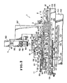
- an automatic apparatus 1 for attaching successive fly strips F one after another to a continuous slide fastener chain in accordance with the invention generally comprises a sewing machine 2, a fly-strip supplier 3 for automatically supplying the successive fly strips one after another to the sewing machine 2, and an element-free gap forming unit 4, for forming element-free gaps in the fastener chain C at a uniform interval of a predetermined distance and for feeding the gapped fastener chain C to the sewing machine 2.
- the sewing machine may be a conventional type on the market. It includes a pair of needles 5 for sewing the fly strips F to the fastener chain C, a cutter 6 for trimming one longitudinal edge of the individual fly strip F, and a needle 7 for overcasting the trimmed longitudinal edge of the individual fly strip F.
- the details of the sewing machine itself are not pertinent here and its detailed description is omitted for clarity.
- the fly-strip supplier 3 includes a fly-strip stacker 8, a picker assembly 9 for picking up the fly strips F one after another from the stacker 8, a first feeder 11 for receiving the fly strips F to a first feed table 10, and a second feeder 13 for feeding the fly strips F from the first feed table 10 to the sewing machine 2 via a second feed table 12.
- the fly-strip stacker 8 includes laterally spaced pair of side plates 15, 15 mounted on a table 14 and connected at their front end by vertically spaced upper and lower stop bars 16, 17.
- a pusher bar 18 of C-shaped cross-section is disposed between the side plates 15, 15 and is slidable on the table 14.
- a link 19 is pivotally connected at one end to one end of the pusher bar 18, and has at the other end a pin 22 slidably received in a slot 21 of a guide 20 fixed on the table 14.
- the two links 19, 23 are pivotally connected at the center to one another in vertically spaced relation by means of a stepped pin 27.
- a reciprocable piston rod 29 extends from a pneumatic cylinder 28 mounted on the table 14, and is pivotally connected at its free end to the link 19 at a position between one end of the link 19 and the stepped pin 27.
- the pusher bar 18 is moved forwardly of the fly-strip stock 8 in parallel relation to the upper and lower stop bars 16, 17 to push a stacked row of the fly strips F against the upper and lower stop bars 16, 17.
- the pusher bar 18 is moved backwardly in the fly-strip stacker 8.
- the picker assembly 9, as shown in Figures 2 and 3, is pivotally connected to the fly-strip stacker 8 at a front upper portion thereof.
- the picker assembly 9 extends between the two side plates 15, 15 and has a swing plate or arm 30 pivotally connected at opposite ends to the respective side plates 15, 15.
- a pair of journals 31, 31 is mounted on opposite ends of the swing plate 30 and extends forwardly therefrom, a shaft 32 being rotatably supported on the journals 31.
- Three serrate picker wheels 33, 33, 33 are concentrically mounted on the shaft 32 and are spaced at equal distances along the shaft 32.
- Three picker pieces 34, each having on its lower end a claw 35, are mounted on the swing plate 30 in opposite relation to the three picker wheels 33, respectively, so that the pieces 34 cooperate with the picker wheels 33 to pick up the individual fly-strip F therebetween.
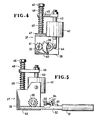
- a drive unit 36 of the picker assembly 9 includes a pivotable housing 37 secured to the right end of the swing plate 30.
- the housing 37 has a pair of side plates 38, 38, between which a shaft 39 is fixed.
- a geneva or sector gear 40 is rotatably mounted on the shaft 39.
- the rotatable shaft 32 extends between the two side plates 38, 38 through the journals 31, and is rotatably supported thereby.
- a small gear 41 is fixed to the rotatable shaft 32 and meshes with the geneva gear 40.
- a pneumatic cylinder 42 is mounted between the two side plates 38, 38.
- a piston rod 43 vertically extends through the pneumatic cylinder 42 and is pivotally connected at its lower end to a projection 44 of the geneva gear 40.
- a lateral arm 45 having a bifurcated end portion is mounted on the upper end of the piston rod 43.
- a bolt 46 extends through the arm 45 at the bifurcated end portion and then threadedly extends into a plate 47 connecting the two side plates 38, 38.
- a pair of compression springs 48, 49 is mounted between the head of the bolt 46 and the arm 45 and between the latter and the plate 47, respectively. Accordingly, when the piston rod 43 of the pneumatic cylinder 42 is moved upwardly or downwardly, the shaft 32 and thus the picker wheel 33 rotates clockwise or counterclockwise, respectively.
- a gear 50 mounted on the fixed shaft about which axis the swing plate 30 is pivotable.
- the gear 50 is fixed to the side plate 38 and meshes with a rack 53 supported by the piston rod 52 of the pneumatic cylinder 51 mounted on the table 14. Accordingly, when the piston rod 52 is extended, the swing plate 30 is pivotally moved upwardly and to the contrary, when the piston rod 52 is retracted, the swing plate 30 is pivotally moved downwardly.
- a stop mechanism 54 is disposed adjacent to the piston rod 52 in order to restrict the extent to which the piston rod 52 is extended, thus restricting the amount of upward pivotal movement of the swing plate 30 for a purpose described below.
- the stop mechanism 55 has a lever 55 pivotally mounted on the upper portion of a bracket 56 mounted on the table 14.
- the lever 55 carries on one end two stop bolts 57, 58 of different lengths threadedly extending into the lever 55.
- the other end of the lever 55 is pivotally connected to the piston rod 60 of the pneumatic cylinder 59.
- the long stop bolt 57 abuts a stop block 61 mounted on the piston rod 52 of the pneumatic cylinder 51.
- the short stop bolt 58 abuts the stop block 61.
- a predetermined number of stop pins 62 are held in an upright frame including a pair of spaced brackets 63, 63 fixed to the upper portions of the two side plates 15, 15 and are also held by a crossbar or bridge plate 64 extending between the two brackets 63, 63.
- the first feed table 10 comprises three spaced table members 65 supported on the table 14 in front of the picker assembly 9 and in parallel relation thereto, each table member 65 including a horizontal plate assembly 70.
- the horizontal plate assembly 70 comprises an upper plate 66, a lower plate 67, and a packing rubber 69 disposed between the upper and lower plates 66, 67 defining therebetween an air chamber 68.
- Each horizontal plate assembly 70 is supported by a pair of legs 71, 71, so that the three horizontal plate assemblies 70, 70, 70 are disposed in a row in a common horizontal plane.
- the upper plate 66 has a plurality of small openings 72 communicating with the air chamber 68, and a stop piece 73 across from the picker 9.
- the three air chambers 68, 68, 68 communicate with one another via a suction pipe 74 disposed below the lower plate 67 so that when a vacuum (not shown) is in operation, the individual fly strip F is stably held on the horizontal plate assemblies 70 by suction.
- the second feed table 12 is disposed on the table 14 in series with respect to the first feed table 10 with a small space between the two feed tables 10, 12.
- a pair of spaced base blocks 75, 75 is mounted on the table 14, each base block 75 having a guide rod 76, 77 extending beyond opposite sides of the respective base block 75.
- a pair of slides 78, 78 is slidably supported by the two guide rods 76, 77.
- the two slides 78, 78 are relatively movably connected to one another via a lever 79 and a pair of links 70, 80 pivotally connected to the lever 79 at opposite ends.
- a shaft 81 rotatably mounted on the table 14 is secured at its upper end to a midportion of the lever 79.
- a radially extending arm 82 is mounted on the shaft 81 at its midportion and is connected at its free end to a piston rod 84 of a pneumatic cylinder 83.
- a guide plate 85 is secured to the upper face of the guide blocks 75, 75 by means of machine screws (not shown).
- a pair of cover plates 86, 86 having an L-shaped cross section is secured to the side faces of the sliders 78, 78, respectively, by means of machine screws 87, 87 ( Figure 1) in such a manner that the cover plates 86, 86 cover the guide plate 85 and also that the top faces of the cover plates 86, 86 are level with the top face of the first feed table 10.
- the respective confronting inner edges 88, 88 of the two cover plates 86, 86 are spaced apart from one another by a distance smaller than the width of the individual fly strip F. Accordingly, when the piston rod 84 of the pneumatic cylinder 83 is extended, the two cover plates 86, 86 are moved toward one another, sliding on the guide rods 76, 77. To the contrary, when the piston rod is retracted, the two cover plates 86, 86 are moved away from each other, leaving a vertical opening facing to the guide plate 85, such that the second feed table 12 has two operating tiers.
- the first feeder 11 is mounted on the table 14 in confronting relation to the picker assembly 9 with the first feed table 10 disposed between the first feeder 11 and the picker assembly 9.
- the first feeder 11 comprises a gripper 93 including upper and lower fingers 91, 92 having at their gripping ends a pair of leaf springs 89, 90, respectively.
- the four upper fingers 91 are supported by both a connecting plate 94 and two connecting rods 95, 95 in spaced relation to one another.
- the four lower fingers 92 are connected by the two connecting rods 96, 96 and are spaced from one another by a distance equal to the distance between the upper fingers 91.
- the four lower fingers 92 are supported by links 97, 97 and are disposed slightly downwardly of the respective upper fingers 91.
- the upper and lower fingers 91, 92 are disposed upwardly and downwardly, respectively, of the top face of the first feed table 10.
- a gripper holder 98 supports at its upper portion the gripper 93 via connecting rods 99, 99 and is secured at its lower portion to the end of a piston rod 101 of a pneumatic cylinder 100 mounted on the table 14. Accordingly, in response to retraction of the piston rod 101, the gripper 93 is moved through the space between the table members 65 of the first feed table 11 and alongside the table members 65. And the gripper 93 returns to its original position in response to extension of the piston rod 101.
- a pair of guide rods 102, 102 is fixed to the lower portion of the gripper holder 98 at opposite sides and is guided by a pair of guide blocks 103, 103, respectively.
- a pneumatic cylinder 106 is disposed between a block 104 mounted on the top of the gripper holder 98 and a projection 105 upwardly extending from one of the links 97.
- the second feeder 13 is disposed above and along the first and second feed tables 10, 12 for feeding the fly strips F on the first feed table 10 to the sewing machine 2 via the second feed table 12.
- a bracket 108 is disposed adjacent to the sewing machine 2.
- Four spaced rods 109 are supported by the bracket 108 and extend horizontally from an upper portion of the bracket 108, free ends of the rods 109 being connected by an end plate 110.
- Two of the four rods 109 are disposed adjacent to the first and second feed tables 10, 12 so that a slide 111 is slidable longitudinally of these two rods 109.
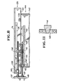
- a pusher unit 112 is mounted on the slider 111 at one side.
- a foot 113 of the pusher unit 112 has at opposite sides a pair of endless belts 114, 114 and at its midportion a projection 115.
- Each belt 114 is moved about a roller 116 and a one-way clutch 117 so as to run only in the direction indicated by an arrow in Figure 9, for a purpose described below.
- An upper end of the projection 115 is pivotally connected, by a pin 121, to a bifurcated projection 120 extending from a shaft 119 rotatably supported by a vertical plate 118.
- the axis of the pin 121 is slightly inclined with respect to the shaft 119 so that the direction in which the belts l14 run is inclined to that extent with respect to the second feed table 12, for a purpose described below.
- the amount of inclination of the pin 121 is adjustable.
- a pair of bolts 122, 123 extends into one end of the foot 113 and a free end of the shaft 119, respectively. Between the two bolts 122, 123 an extension spring 124 is mounted in order to stabilize the position of the foot 113.
- a projection 125 extends upwardly from a midportion of the shaft 119, and is pivotally connected at its upper end to the end of a piston rod 127 of a pneumatic cylinder 126 pivotally mounted at one end on the vertical plate 118.
- the power transmission 132 is operative to transmit rotation of the driving shaft of a non-illustrated motor to the screw 129, with or without changing the direction of that rotation by means of an electromagnetic clutch (not shown).
- the electromagnetic clutch 131 is operative to disconnect the screw 129 from the non-illustrated motor, thus stopping rotation of the screw 129.
- the screw 129 may be rotated in either direction, or may be kept from being rotated, as desired.
- the table 14 which supports the fly-strip supplier 3, is supported on an upper support 135 which includes a pair of side plates 133, 133 connected by a pair of pipes 134, 134 having a rectangular cross section.
- a pair of L-shaped guide rails 136, 136 is secured to the underside of the table 14 by means of bolts. With the engagement between the rails 136 and the side plates 133, the table 14 is movable vertically (as viewed in Figure 2) with respect to the support 135.
- a handle 137 is provided on the front of the table 14 in order to facilitate this movement of the table 14.
- a screw 138 extends from the handle 137 through a journal 139 fixed to the underside of the table 14, and then threadedly extends through a nut 140 fixed to the rectangular pipe 134. The accidental removal of the screw 138 is prevented by a pair of stop rings 141, 141 disposed one on each side of the journal 139.
- the upper support 135 is in turn supported on a lower support 144 which includes a pair of side plates 142, 142 and a horizontal plate 143 extending between the two side plates 142, 142.
- a pivot receptor 145 (Figure 11) is fixed to the top of the horizontal plate 143 so as to be disposed under the second feed table 12.
- the pivot receptor 145 is receptive of a pivot 146 fixed to the underside of the upper support 135 so that the upper support 135 can be pivotally moved on the lower support 144 in the directions indicated by the arrows 147 ( Figure 2).
- a handle 148 is provided on the front of the lower support 144 in order to facilitate this pivotal movement of the upper support 135.
- a screw 149 extends from the handle 148 through a journal 150 fixed to the top of the horizontal plate 143, and thenthreadedly extends through a nut 151 fixed to the underside of the rectangular pipe 134. The accidental removal of the screw 149 is prevented by a pair of stop rings 152, 152 disposed one on each side of the journal 150.
- the nut 151 has a shaft 153 extending upwardly through the rectangular pipe 134, and is thereby rotatably mounted on the rectangular pipe 134.
- the sewing machine 2 is mounted on a plate 154 which is in turn fixed to the left side plate 142 of the lower support 144.
- the sewing station 155 of the sewing machine 2 is disposed adjacent to the second feed table 12, and is slightly inclined with respect thereto, as shown in Figure 2.
- the element-free gap forming unit 4 for forming a plurality of element-free gaps G devoid of coupling elements in the fastener chain C at uniform intervals of a predetermined distance, is disposed above the first and second feed tables 10, 12.
- the gap forming unit 4 is mounted on a post 157 fixed to the horizontal plate 143 and extending upwardly through an opening 156 of the table 14.
- the gap forming unit 4 includes a conventional punch unit 158, a die 159, a solenoid 160 for moving the punch 158, and a plunger 161 connecting the solenoid 160 with the punch 158. Any of these members of the gap forming unit 4 has a known construction, and therefore, its detailed description is omitted for clarity.
- a pair of spaced guide rollers 162, 162 is disposed at the right side of the punch 158 and die 159, and a chain feed roller 163 is disposed between the two guide rollers 162, 162.
- a pair of upper and lower brushing rollersl64, 164 for brushing off the cut element leg portions left on the stringer tapes after gapping there are disposed a pair of upper and lower brushing rollersl64, 164 for brushing off the cut element leg portions left on the stringer tapes after gapping, a take-up roller 165, and a pinch roller 166.
- the chain feed roller 163 is operatively connected to a motor 167 ( Figure 3) disposed rearwardly of the feed roller 163.
- the motor 167 has a pulse generator (not shown) therein for producing pulses indicating the amount of rotation of the motor 167 caused by movement of the fastener chain through the sewing station to control the operation of the gapping punch 158.
- the number of pulses that occur prior to energization of the punch 158 is determined by the length of the fly pieces in the stack F. This length may be sensed each time the stacker is loaded by, for example, a measuring slide 165a ( Figure 2) driving a rotor 165b of the same diameter as the roller 165 providing a total pulse reading representing the length of the fly pieces and controlling the number of pulses at the roller 165 upon the occurrence of which the punch 158 is actuated.
- the fastener chain C having thus been gapped is introduced into the sewing station 155 of the sewing machine 2 through a chain guide 168.
- a chain guide 168 At the sewing station 155, successive fly strips F are sewn one after another to the fastener chain C.
- the chain guide 168 is fixed to a free end of an arm 170 pivotally mounted on a casing of the sewing machine 2 by a pin 169.
- a timer (not shown) is actuated (the timer is energized when the element-free gap G is sensed), whereupon the piston rod 127 of the pneumatic cylinder 126 is retracted, causing the foot 113 to rise.
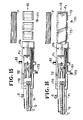
- the cover plates 86, 86 are opened and closed, thus allowing the fly strip Fl to fall on the guide plate 85 and then covering the same fly strip F 1 . as shown in Figure 14.
- a limit switch (not shown) is actuated to energize the electromagnetic clutch 131 (the power transmission 132 is in condition for reverse rotation, as described below). Accordingly, the pusher unit 112 is retracted to a position above the first feed table 10 is hit on its actuator by the slide 111 ( Figure 14).
- the electromagnetic clutch 131 is thereby de-energized, and the power transmission l32 is in condition for rotation in the same direction as that of the motor's rotation, thus stopping the pusher unit 112.
- the foot 113 is lowered onto the fly strip F 2 on the first feed table 10, and at the same time, a timer (not shown) is energized.
- the electromagnetic clutch 131 is energized, causing the pusher unit 112 to push the fly strip F 2 from the first feed table 10 to the second feed table 12.
- the electromagnetic clutch 131 When the leading end of the fly strip F 2 is sensed by a sensor 172 (including a photoelectric transducer), the electromagnetic clutch 131 is de-energized, causing the pusher unit 112 to stop. The fly strip F 2 is thus stopped at that position. During that time, the limit switch 173 is hit on its actuator by the slider 111 ( Figure 15) at intervals.
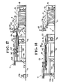
- the gripper 93 As the piston rod 101 of the pneumatic cylinder 100 is extended in response to actuation of the non-illustrated timer, the gripper 93 is retracted, hitting the limit switch 177 on its actuator, and then stopped. On the backward stroke of the gripper 93, the fly strip F 3 is engaged by the stop piece 73 of the first feed table 10 is thereby released from the leaf springs 89, 90 of the fingers 91, 92, and is thereby disposed on the feed table 10 in flat condition, as shown in Figures 16 and 18.
- the guide rod 102 and the valve 178 ( Figure 2) are disengaged from one another to open the valve 178, thus allowing the piston rod 48 of the pneumatic cylinder 42 to return to its original position.
- the valve 176 is opened by the gripper holder 98, terminating the suction of the first feed table 10.
- the piston rod 107 of the pneumatic cylinder 106 is extended, causing the gripper 93 to open. At the same time the non-illustrated switch is energized. Also upon actuation of the limit switch 177, the piston rod 29 of the pneumatic cylinder 28 for the fly strip stacker 8 is extended, indexing the fly strip F against the upper and lower stop bars 16, 17. Further upon actuation of the limit switch 177, the piston rod 52 of the pneumatic cylinder 51 is retracted, causing the swing plate 30 to be pivotally moved downwardly until it abuts the leading surface of the uppermost fly strip F 4 of the fly strip stack.
- a discrimination between front and reverse sides of the fly strip is afforded by the inventive apparatus. If the side of the fly strip F that faces the sensor 179 (e.g. a photoelectric sensor) is the front, such as denoted by exterior finishing or different shading with colored fabrics, the piston rod 60 of the pneumatic cylinder 59 for the stop mechanism 54 ( Figures 1 and 2) is retracted, the long stop bolt 57 being held so as to abut the stop block 61. To the contrary, if the side of the uppermost fly strip F that faces the sensor 179 is the reverse, the piston rod 60 is extended, the short stop bolt 58 being held so as to abut the stop block 61.
- successive fly strips are usually stacked in such a manner that every other fly strip is disposed front side down.
- an alternating switch may be provided, overriding the sensor. Similarly, if all fly pieces are stacked with the same side up, the sensor may be overridden and the appropriate stop selected.
- the piston rod 52 of the pneumatic cylinder 51 for the fly strip stock 8 is extended until the stop block 61 strikes the stop bolt 57.
- the swing arm 30, with the fly strip F 4 picked thereby, is turned clockwise in Figure 20, and stops and waits with one side edge of the fly strip F 4 touching the stop pin 62, such that the fly strip 4 will have been reoriented 90° about its linear axis when deposited on the first feed table 10. If the leading or uppermost fly strip F 4 is placed reverse side up, the piston rod 52 is extended until the short stop bolt 58 strikes the stop block 61.
- the swing arm 30 stops and waits with the other side edge of the fly strip F touching the stop pin 62 as shown in Figure 21, such that the fly strip F 4 will have been reoriented 270°, about its linear axis when deposited on the first feed table 10.
- the element-free gap G of the fastener chain C is sensed by the sensor 180 (such as a photoelectric transducer).
- the electromagnetic clutch 131 is thereby energized, and the pusher unit 112 is advanced, thus supplying the fly strip F2 again to the sewing station 155 in such a timed relation that the leading end of the fly strip F 2 is aligned with the corresponding element-free gap G.
- the electromagnetic clutch 131 In response to energization of the non-illustrated timer, the electromagnetic clutch 131 is deenergized, and the power transmission 132 is in condition for reverse rotation.
- the apparatus of the present invention may be used to attach the fly strips to either a pre-gapped fastener chain or a non-gapped fastener chain.
- pre-gapped fastener chain it is directly threaded through the chain guide 168 and is then introduced into the sewing station 155.
- non-gapped fastener chain it is introduced into the sewing station 155 via the guide rollers 162, 162, the chain feed roller 163 and the chain guide 168. In the latter case, the photoelectric sensor 180 does not work.
Applications Claiming Priority (2)
| Application Number | Priority Date | Filing Date | Title |
|---|---|---|---|
| US502310 | 1983-06-08 | ||
| US06/502,310 US4541352A (en) | 1983-06-08 | 1983-06-08 | Method of and apparatus for attaching fly strips to a slide fastener chain |
Publications (3)
| Publication Number | Publication Date |
|---|---|
| EP0129146A2 true EP0129146A2 (fr) | 1984-12-27 |
| EP0129146A3 EP0129146A3 (en) | 1987-09-16 |
| EP0129146B1 EP0129146B1 (fr) | 1990-12-19 |
Family
ID=23997240
Family Applications (1)
| Application Number | Title | Priority Date | Filing Date |
|---|---|---|---|
| EP84106441A Expired - Lifetime EP0129146B1 (fr) | 1983-06-08 | 1984-06-06 | Méthode et appareil pour attacher une chaîne d'éléments de fermeture à une bande de braguette |
Country Status (14)
| Country | Link |
|---|---|
| US (1) | US4541352A (fr) |
| EP (1) | EP0129146B1 (fr) |
| JP (1) | JPS6017161A (fr) |
| KR (1) | KR870001031B1 (fr) |
| AU (1) | AU557049B2 (fr) |
| BR (1) | BR8402820A (fr) |
| CA (1) | CA1241527A (fr) |
| DE (1) | DE3483756D1 (fr) |
| ES (3) | ES8503492A1 (fr) |
| FI (1) | FI84631C (fr) |
| GB (2) | GB2141144B (fr) |
| HK (2) | HK26889A (fr) |
| SG (1) | SG83488G (fr) |
| ZA (1) | ZA844327B (fr) |
Cited By (1)
| Publication number | Priority date | Publication date | Assignee | Title |
|---|---|---|---|---|
| GB2340135A (en) * | 1998-07-23 | 2000-02-16 | Ykk Corp | Trousers-fly-sewing apparatus |
Families Citing this family (19)
| Publication number | Priority date | Publication date | Assignee | Title |
|---|---|---|---|---|
| US4660821A (en) * | 1983-06-08 | 1987-04-28 | Yoshida Kogyo K.K. | Method of and apparatus for attaching fly strips to a slide fastener chain |
| US4611546A (en) * | 1984-08-23 | 1986-09-16 | Yoshida Kogyo K. K. | Apparatus for attaching fly strips to a slide fastener chain |
| US4576104A (en) * | 1984-09-14 | 1986-03-18 | Yoshida Kogyo K. K. | Method and apparatus for attaching fly strips to a slide fastener chain |
| JPS61164588A (ja) * | 1985-01-17 | 1986-07-25 | 佐藤精器株式会社 | 自動ポケツト縫製機の補助機構 |
| JPS61203903A (ja) * | 1985-03-08 | 1986-09-09 | ワイケイケイ株式会社 | スライドフアスナ−の縫着方法とその装置 |
| JPS61206403A (ja) * | 1985-03-08 | 1986-09-12 | ワイケイケイ株式会社 | スライドフアスナ−用縫製機におけるスライダ−摺動装置 |
| US4714038A (en) * | 1986-08-07 | 1987-12-22 | Yoshida Kogyo K. K. | Method for sewing zipper chain to elongated fabric pieces |
| US4674422A (en) * | 1986-08-07 | 1987-06-23 | Yoshida Kogyo K. K. | Apparatus for sewing zipper chain to elongated fabric pieces |
| DE3812800C2 (de) * | 1988-04-16 | 1996-11-21 | Hans Dipl Ing Scholl | Verfahren zum Anbringen eines Stoffstreifens mit einem Reißverschlußteil an einer Vorderhose und Näheinheit zur Durchführung des Verfahrens |
| US5016549A (en) * | 1989-01-24 | 1991-05-21 | Kochs Alder Aktiengesellschaft | Attaching a strip of cloth with a zip-fastener component to a trouser forepart |
| US4979450A (en) * | 1989-07-03 | 1990-12-25 | Yoshida Kogyo K.K. | Method and apparatus for sewing fly pieces to a slide fastener chain |
| US5067424A (en) * | 1990-09-07 | 1991-11-26 | Yoshida Kogyo K.K. | Apparatus for sewing fabric pieces to slide fastener chain |
| FR2699893B1 (fr) * | 1992-12-31 | 1995-02-24 | Eclair Prestil | Emballage de fermeture à glissière et procédé et dispositif de réalisation de celui-ci. |
| FR2703935B1 (fr) * | 1993-04-14 | 1995-07-21 | Usinor Sacilor | Dispositif de changement rapide et de maintien d'une paroi laterale d'une machine de coulee continue d'un produit metallique entre cylindres. |
| JPH0910459A (ja) * | 1995-06-30 | 1997-01-14 | Ykk Kk | 長尺スライドファスナーチェーンに生地片を一連に縫着する方法及び装置 |
| GB2578170B (en) * | 2018-10-19 | 2023-05-17 | Vegware Ltd | The combination of two containers with a lid suitable to fit either |
| IT201900006726A1 (it) * | 2019-05-10 | 2020-11-10 | Tor Mec Ambrosi S R L | Unita’ automatica atta ad eseguire l’allineamento del materiale e la cucitura programmabile sulla parte anteriore di un pantalone |
| US11284605B1 (en) | 2020-06-26 | 2022-03-29 | Ideam Llc | Birdfeeders with multiple feeding ports |
| CN112471708B (zh) * | 2020-12-03 | 2022-02-18 | 浙江敏杰新材料科技有限公司 | 一种拉链生产用自动拼链装置 |
Citations (12)
| Publication number | Priority date | Publication date | Assignee | Title |
|---|---|---|---|---|
| FR876823A (fr) * | 1940-07-15 | 1942-11-18 | Machine à coudre en opération continue des pièces en plusieurs parties | |
| US3420386A (en) * | 1966-04-15 | 1969-01-07 | Magnacraft Mfg Co | Stacking machine |
| DE1460108A1 (de) * | 1964-03-12 | 1969-01-30 | L & L Mfg Inc | Vorrichtung und Verfahren zum Trennen von Stoffstuecken von einem Stapel od.dgl. |
| US3618546A (en) * | 1970-04-01 | 1971-11-09 | Automated Components Inc | Garment stacking apparatus |
| US3773002A (en) * | 1971-12-29 | 1973-11-20 | P Burton | Method and apparatus for folding and sewing hems |
| GB1338785A (en) * | 1972-06-14 | 1973-11-28 | Pasolds Ltd | Automatic flexible sheet material piece feeding |
| US3871309A (en) * | 1970-10-08 | 1975-03-18 | Oxford Industries | Shirt front assembly, method and apparatus |
| US4040366A (en) * | 1975-04-16 | 1977-08-09 | Silverman Machines, Inc. | Automatic hemming apparatus |
| DE2657230A1 (de) * | 1976-12-17 | 1978-06-29 | Pfaff Ind Masch | Vorrichtung zum vereinzeln textiler werkstuecke von einem stapel |
| US4157823A (en) * | 1974-05-17 | 1979-06-12 | Cluett, Peabody & Co., Inc. | Method and means for transporting and orienting limp plys of fabric or the like |
| EP0020258A1 (fr) * | 1979-05-29 | 1980-12-10 | ANVAR Agence Nationale de Valorisation de la Recherche | Procédé et installation de manutention pour amener une pièce à un poste d'arrivée dans une position prédéterminée |
| GB2088913A (en) * | 1964-03-23 | 1982-06-16 | Talon Inc | Method and semi-automatic apparatus for sewing flypieces to slide fastener chain |
Family Cites Families (5)
| Publication number | Priority date | Publication date | Assignee | Title |
|---|---|---|---|---|
| GB968178A (en) * | 1962-07-30 | 1964-08-26 | Singer Co | Air operated separator for stacked textile work pieces |
| US4362116A (en) * | 1980-12-10 | 1982-12-07 | Talon, Inc. | Method and semi-automatic apparatus for sewing flypieces to slide fastener chain |
| US4152996A (en) * | 1977-02-14 | 1979-05-08 | Textron Inc. | Method for sewing trouser-fly units and the like |
| JPS581314U (ja) * | 1981-06-24 | 1983-01-06 | ワイケイケイ株式会社 | 間欠スライドフアスナ−チエ−ンの製造装置 |
| US4497270A (en) * | 1983-09-26 | 1985-02-05 | Yoshida Kogyo K.K. | Method and apparatus for sewing elongated fabric piece |
-
1983
- 1983-06-08 US US06/502,310 patent/US4541352A/en not_active Expired - Fee Related
-
1984
- 1984-05-28 CA CA000455249A patent/CA1241527A/fr not_active Expired
- 1984-05-30 AU AU28838/84A patent/AU557049B2/en not_active Ceased
- 1984-06-04 ES ES533095A patent/ES8503492A1/es not_active Expired
- 1984-06-04 ES ES533094A patent/ES533094A0/es active Granted
- 1984-06-04 ES ES533096A patent/ES8503493A1/es not_active Expired
- 1984-06-06 DE DE8484106441T patent/DE3483756D1/de not_active Expired - Lifetime
- 1984-06-06 BR BR8402820A patent/BR8402820A/pt not_active IP Right Cessation
- 1984-06-06 GB GB08414427A patent/GB2141144B/en not_active Expired
- 1984-06-06 EP EP84106441A patent/EP0129146B1/fr not_active Expired - Lifetime
- 1984-06-06 FI FI842289A patent/FI84631C/fi not_active IP Right Cessation
- 1984-06-07 ZA ZA844327A patent/ZA844327B/xx unknown
- 1984-06-07 JP JP59117419A patent/JPS6017161A/ja active Granted
- 1984-06-07 KR KR1019840003163A patent/KR870001031B1/ko not_active IP Right Cessation
-
1986
- 1986-05-23 GB GB08612620A patent/GB2174113B/en not_active Expired
-
1988
- 1988-11-30 SG SG834/88A patent/SG83488G/en unknown
-
1989
- 1989-03-30 HK HK268/89A patent/HK26889A/xx unknown
- 1989-03-30 HK HK269/89A patent/HK26989A/xx unknown
Patent Citations (12)
| Publication number | Priority date | Publication date | Assignee | Title |
|---|---|---|---|---|
| FR876823A (fr) * | 1940-07-15 | 1942-11-18 | Machine à coudre en opération continue des pièces en plusieurs parties | |
| DE1460108A1 (de) * | 1964-03-12 | 1969-01-30 | L & L Mfg Inc | Vorrichtung und Verfahren zum Trennen von Stoffstuecken von einem Stapel od.dgl. |
| GB2088913A (en) * | 1964-03-23 | 1982-06-16 | Talon Inc | Method and semi-automatic apparatus for sewing flypieces to slide fastener chain |
| US3420386A (en) * | 1966-04-15 | 1969-01-07 | Magnacraft Mfg Co | Stacking machine |
| US3618546A (en) * | 1970-04-01 | 1971-11-09 | Automated Components Inc | Garment stacking apparatus |
| US3871309A (en) * | 1970-10-08 | 1975-03-18 | Oxford Industries | Shirt front assembly, method and apparatus |
| US3773002A (en) * | 1971-12-29 | 1973-11-20 | P Burton | Method and apparatus for folding and sewing hems |
| GB1338785A (en) * | 1972-06-14 | 1973-11-28 | Pasolds Ltd | Automatic flexible sheet material piece feeding |
| US4157823A (en) * | 1974-05-17 | 1979-06-12 | Cluett, Peabody & Co., Inc. | Method and means for transporting and orienting limp plys of fabric or the like |
| US4040366A (en) * | 1975-04-16 | 1977-08-09 | Silverman Machines, Inc. | Automatic hemming apparatus |
| DE2657230A1 (de) * | 1976-12-17 | 1978-06-29 | Pfaff Ind Masch | Vorrichtung zum vereinzeln textiler werkstuecke von einem stapel |
| EP0020258A1 (fr) * | 1979-05-29 | 1980-12-10 | ANVAR Agence Nationale de Valorisation de la Recherche | Procédé et installation de manutention pour amener une pièce à un poste d'arrivée dans une position prédéterminée |
Cited By (3)
| Publication number | Priority date | Publication date | Assignee | Title |
|---|---|---|---|---|
| GB2340135A (en) * | 1998-07-23 | 2000-02-16 | Ykk Corp | Trousers-fly-sewing apparatus |
| US6092479A (en) * | 1998-07-23 | 2000-07-25 | Ykk Corporation | Trousers-fly-sewing apparatus |
| GB2340135B (en) * | 1998-07-23 | 2002-08-07 | Ykk Corp | Trousers-fly-sewing apparatus |
Also Published As
| Publication number | Publication date |
|---|---|
| FI84631C (fi) | 1991-12-27 |
| HK26989A (en) | 1989-04-07 |
| FI84631B (fi) | 1991-09-13 |
| KR850000055A (ko) | 1985-02-25 |
| ES533096A0 (es) | 1985-04-01 |
| ES8503491A1 (es) | 1985-04-01 |
| ES533095A0 (es) | 1985-04-01 |
| GB8612620D0 (en) | 1986-07-02 |
| SG83488G (en) | 1989-04-14 |
| GB2141144B (en) | 1987-06-03 |
| GB2141144A (en) | 1984-12-12 |
| JPS6017161A (ja) | 1985-01-29 |
| JPS6328635B2 (fr) | 1988-06-09 |
| ES8503493A1 (es) | 1985-04-01 |
| US4541352A (en) | 1985-09-17 |
| ES533094A0 (es) | 1985-04-01 |
| DE3483756D1 (de) | 1991-01-31 |
| GB2174113B (en) | 1987-06-03 |
| ZA844327B (en) | 1985-01-30 |
| GB8414427D0 (en) | 1984-07-11 |
| CA1241527A (fr) | 1988-09-06 |
| ES8503492A1 (es) | 1985-04-01 |
| HK26889A (en) | 1989-04-07 |
| AU557049B2 (en) | 1986-12-04 |
| FI842289A (fi) | 1984-12-09 |
| GB2174113A (en) | 1986-10-29 |
| FI842289A0 (fi) | 1984-06-06 |
| KR870001031B1 (ko) | 1987-05-25 |
| EP0129146A3 (en) | 1987-09-16 |
| EP0129146B1 (fr) | 1990-12-19 |
| AU2883884A (en) | 1984-12-13 |
| BR8402820A (pt) | 1985-05-21 |
Similar Documents
| Publication | Publication Date | Title |
|---|---|---|
| EP0129146B1 (fr) | Méthode et appareil pour attacher une chaîne d'éléments de fermeture à une bande de braguette | |
| US4660821A (en) | Method of and apparatus for attaching fly strips to a slide fastener chain | |
| EP0141252B1 (fr) | Procédé et appareil pour coudre des articles longilignes | |
| CA1237882A (fr) | Methode et dispositif de finition automatique de fermetures a glissiere | |
| US4287842A (en) | Automatic belt loop tacker | |
| US4718158A (en) | Automatic tagging apparatus and method therefor | |
| EP0159507B1 (fr) | Dispositif de tirage d'un article cousu de grande longueur hors du point de couture | |
| US4674422A (en) | Apparatus for sewing zipper chain to elongated fabric pieces | |
| US5077884A (en) | Apparatus for manufacturing slide fasteners | |
| CA1312004C (fr) | Dispositif de decharge pour dispositif a decouper des articles de forme ovale | |
| DE2721510A1 (de) | Automatische naehmaschine | |
| CA1193423A (fr) | Methode et dispositif de montage des glissieres sur des fermetures en serie | |
| US3761073A (en) | Device for automatically guiding material during seam formation | |
| US3980033A (en) | Placket buttonhole system | |
| EP0160917B1 (fr) | Appareil pour la fermeture automatique d'une fermeture à glissière | |
| US4714038A (en) | Method for sewing zipper chain to elongated fabric pieces | |
| US4385571A (en) | Automatic belt loop tacker | |
| EP0288213B1 (fr) | Appareil pour traiter un article allongé avec un dispositif de déchargement | |
| US4483529A (en) | Tag transport method | |
| US4474125A (en) | Tag attaching machine | |
| JPS61206403A (ja) | スライドフアスナ−用縫製機におけるスライダ−摺動装置 |
Legal Events
| Date | Code | Title | Description |
|---|---|---|---|
| PUAI | Public reference made under article 153(3) epc to a published international application that has entered the european phase |
Free format text: ORIGINAL CODE: 0009012 |
|
| AK | Designated contracting states |
Designated state(s): BE CH DE FR IT LI NL SE |
|
| PUAL | Search report despatched |
Free format text: ORIGINAL CODE: 0009013 |
|
| AK | Designated contracting states |
Kind code of ref document: A3 Designated state(s): BE CH DE FR IT LI NL SE |
|
| 17P | Request for examination filed |
Effective date: 19871218 |
|
| 17Q | First examination report despatched |
Effective date: 19890321 |
|
| GRAA | (expected) grant |
Free format text: ORIGINAL CODE: 0009210 |
|
| AK | Designated contracting states |
Kind code of ref document: B1 Designated state(s): BE CH DE FR IT LI NL SE |
|
| ITF | It: translation for a ep patent filed |
Owner name: JACOBACCI & PERANI S.P.A. |
|
| ET | Fr: translation filed | ||
| REF | Corresponds to: |
Ref document number: 3483756 Country of ref document: DE Date of ref document: 19910131 |
|
| PLBE | No opposition filed within time limit |
Free format text: ORIGINAL CODE: 0009261 |
|
| STAA | Information on the status of an ep patent application or granted ep patent |
Free format text: STATUS: NO OPPOSITION FILED WITHIN TIME LIMIT |
|
| 26N | No opposition filed | ||
| ITTA | It: last paid annual fee | ||
| PGFP | Annual fee paid to national office [announced via postgrant information from national office to epo] |
Ref country code: SE Payment date: 19940310 Year of fee payment: 11 |
|
| PGFP | Annual fee paid to national office [announced via postgrant information from national office to epo] |
Ref country code: BE Payment date: 19940316 Year of fee payment: 11 |
|
| PGFP | Annual fee paid to national office [announced via postgrant information from national office to epo] |
Ref country code: FR Payment date: 19940420 Year of fee payment: 11 |
|
| PGFP | Annual fee paid to national office [announced via postgrant information from national office to epo] |
Ref country code: CH Payment date: 19940607 Year of fee payment: 11 |
|
| PGFP | Annual fee paid to national office [announced via postgrant information from national office to epo] |
Ref country code: NL Payment date: 19940630 Year of fee payment: 11 Ref country code: DE Payment date: 19940630 Year of fee payment: 11 |
|
| REG | Reference to a national code |
Ref country code: CH Ref legal event code: PFA Free format text: YKK CORPORATION |
|
| ITPR | It: changes in ownership of a european patent |
Owner name: CAMBIO RAGIONE SOCIALE;YKK CORPORATION |
|
| REG | Reference to a national code |
Ref country code: FR Ref legal event code: CD |
|
| EAL | Se: european patent in force in sweden |
Ref document number: 84106441.3 |
|
| NLT1 | Nl: modifications of names registered in virtue of documents presented to the patent office pursuant to art. 16 a, paragraph 1 |
Owner name: YKK CORPORATION TE TOKIO, JAPAN. |
|
| PG25 | Lapsed in a contracting state [announced via postgrant information from national office to epo] |
Ref country code: SE Effective date: 19950607 |
|
| PG25 | Lapsed in a contracting state [announced via postgrant information from national office to epo] |
Ref country code: LI Effective date: 19950630 Ref country code: CH Effective date: 19950630 Ref country code: BE Effective date: 19950630 |
|
| BERE | Be: lapsed |
Owner name: YKK CORP. Effective date: 19950630 |
|
| PG25 | Lapsed in a contracting state [announced via postgrant information from national office to epo] |
Ref country code: NL Effective date: 19960101 |
|
| PG25 | Lapsed in a contracting state [announced via postgrant information from national office to epo] |
Ref country code: FR Effective date: 19960229 |
|
| REG | Reference to a national code |
Ref country code: CH Ref legal event code: PL |
|
| NLV4 | Nl: lapsed or anulled due to non-payment of the annual fee |
Effective date: 19960101 |
|
| PG25 | Lapsed in a contracting state [announced via postgrant information from national office to epo] |
Ref country code: DE Effective date: 19960301 |
|
| EUG | Se: european patent has lapsed |
Ref document number: 84106441.3 |
|
| REG | Reference to a national code |
Ref country code: FR Ref legal event code: ST |