EP0128418A1 - Betonbehälter zur Aufnahme bioschädlicher Stoffe - Google Patents
Betonbehälter zur Aufnahme bioschädlicher Stoffe Download PDFInfo
- Publication number
- EP0128418A1 EP0128418A1 EP84105902A EP84105902A EP0128418A1 EP 0128418 A1 EP0128418 A1 EP 0128418A1 EP 84105902 A EP84105902 A EP 84105902A EP 84105902 A EP84105902 A EP 84105902A EP 0128418 A1 EP0128418 A1 EP 0128418A1
- Authority
- EP
- European Patent Office
- Prior art keywords
- concrete
- outer shell
- container according
- inner shell
- concrete container
- Prior art date
- Legal status (The legal status is an assumption and is not a legal conclusion. Google has not performed a legal analysis and makes no representation as to the accuracy of the status listed.)
- Granted
Links
Images


Classifications
-
- G—PHYSICS
- G21—NUCLEAR PHYSICS; NUCLEAR ENGINEERING
- G21F—PROTECTION AGAINST X-RADIATION, GAMMA RADIATION, CORPUSCULAR RADIATION OR PARTICLE BOMBARDMENT; TREATING RADIOACTIVELY CONTAMINATED MATERIAL; DECONTAMINATION ARRANGEMENTS THEREFOR
- G21F5/00—Transportable or portable shielded containers
- G21F5/005—Containers for solid radioactive wastes, e.g. for ultimate disposal
Definitions
- the invention relates to a concrete container with steel reinforcement for receiving bio-harmful substances, in particular for receiving radioactive waste, consisting of a base body with a lid and suspension devices.
- Bio-harmful substances such as hazardous industrial waste and in particular radioactive waste from nuclear facilities, industry and hospitals, must be packed according to the legal requirements before they can be stored in a suitable landfill.
- Concrete containers are often used for this purpose, in which the bio-harmful substances usually enclosed by sheet metal packaging are introduced.
- the concrete containers must be designed to be stable and, in some cases, shield radioactive radiation so that the safety of the biosphere during handling, transport and during intermediate and final storage is guaranteed. This applies particularly to accident situations.
- the present invention was therefore based on the object of creating a concrete container with steel reinforcement for receiving bio-harmful substances, in particular for receiving radioactive waste, consisting of a base body with a lid and suspension devices which, even in the event of improper handling, accidents and damage fire, ensure the safe containment of the container inventory enables without endangering the environment.
- the base body consists of an inner shell and an outer shell, the concrete of the thinner outer shell having a lower compressive strength than the concrete of the inner shell.
- the lid of the container can also be constructed accordingly.
- the thickness of the outer shell is preferably 2 to 6 cm and is made of a porous concrete. It is also beneficial if the concrete of the outer shell contains foamed plastic beads. It is also advantageous if a layer of non-combustible, poorly heat-conducting plastics, glass fibers or graphite fibers is arranged between the inner shell and the outer shell.
- the inner shell is preferably connected to the outer shell by predetermined breaking points and / or anchors having deformation areas.
- the suspension devices of the concrete container are advantageously connected to the reinforcement of the inner shell via links and / or deformation elements forming predetermined breaking points. In addition, they can also be connected to the reinforcement of the outer shell. It has also proven to be advantageous if the links and the deformation elements are embedded in concrete or other damping material, for which purpose a concrete is used which has the concrete quality of the outer shell.
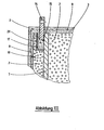
- Figures I to IV schematically show a concrete container according to the invention in an exemplary embodiment, Figure I a longitudinal section, Figure II the details between the inner and outer shell and Figures III and IV the arrangement of the suspension devices.
- the cylindrical, cube-shaped or cuboid concrete container consists of a base body (1) and a cover (5), both of which are provided with steel reinforcement (7).
- suspension devices in the form of eyelets (14) or corner fittings (16) are attached to the concrete container.
- the radioactive substances are located inside the container, mostly enclosed in a metal barrel (6).
- the space between the metal barrel (6), base body (1) and cover (5) can contain a backfill material.
- the base body (1) and optionally also the cover (5) consist of an inner shell (2) and an outer shell (3).
- the inner shell (2) is made of concrete with high compressive strength, e.g. B.
- Heavy concrete (compressive strength: 60-64 N / mm 2 , density: 3.5-3.7 g / cm 3 ) and has a significantly greater thickness compared to the outer shell (3) made of lower strength concrete. While the concrete thickness of the inner shell (2) can often be 15 to 20 cm, the thickness of the outer shell (3) is less than 10 cm.
- the outer shell (3) is provided with a reinforcement (8) which is less in comparison to the strong steel reinforcement (7) of the inner shell (2), which fulfills the safety, carrying, stability and possibly the main radiation shielding function Strength is.
- the reinforcement (8) consists of a wire mesh, corrugated perforated plate or a suitable wire spiral.
- the outer shell (3) takes on energy-absorbing shock absorption and predetermined breaking functions on the container due to the correspondingly selected low concrete quality in connection with the smaller layer thickness and the weaker reinforcement.
- the outer shell (3) In the event of damage, only the outer shell (3) is damaged or broken without the safety functions of the inner shell (2) being impaired. This also applies to a damage fire that may damage the outer shell (2). It has proven to be favorable for shock absorption if the outer shell (3) has a thickness of 3 to 6 cm. For reasons of weight, damping and heat insulation, it is advantageous to use porous concrete as the material for the outer shell (3). Suitable for this include Gas concrete, natural pumice concrete, expanded clay and expanded slate concrete, cottage pumice concrete and ash sinter concrete. It is particularly advantageous if the concrete of the outer shell (3) contains foamed plastic balls.
- a layer (4) made of non-combustible plastics eg, between the inner shell (2) and the outer shell (3).
- B. in foamed form, glass fibers, for example as mats, or graphite fibers, e.g. B. is arranged as a tile.
- This layer (4) additionally improves shock absorption and thermal insulation because of the elastic properties of the materials mentioned.
- the concrete container according to the invention is easy to manufacture.
- the inner shell (2) which is provided with anchors (10) on the outside, can be manufactured. It may be possible to reinforce the outer area of the inner shell (2) by pouring in mats or wire. Then, by pouring out the space between the inner shell (2) and a concrete casting mold, the outer shell (3) is cast over the anchor fasteners (11). The layer (4) is placed around the already concreted inner shell (2) before concreting the outer shell (3). Concreting the outer shell (3) in the area of the cover and the end face also presents no difficulties.
- the inner shell (2) is connected to the outer shell (3) by predetermined breaking points (11) and / or anchors (13) having deformation areas (12).
- Iron rods or wires can be used as anchors (13) with predetermined breaking points (11), the cross-section of which at the predetermined breaking point (11), which are located either within the outer shell (3), within the layer (4) or in the interface area of the two shells, is weakened accordingly.
- Anchors can also be used that slide into one another as two parts when a permissible pressure load is exceeded due to shearing.
- Anchors are anchors (13) with deformation areas (12), which can be in corresponding positions as the predetermined breaking points (11) Can be used with beads or spiral spring-like anchors.
- the anchors (13) either absorb deformation energy or cause the outer shell (3) to flake off and crumble to dissipate energy if necessary.
- suspension devices (14, 16) are connected to the reinforcement (7) via links (15, 19) and / or deformation elements (18) forming predetermined breaking points, the links (15, 19) or the deformation elements (18) of concrete (20), the quality of which corresponds to the concrete quality of the outer layer (3), or are surrounded by other damping material.
- the suspension devices (14, 16) are additionally connected to the reinforcement (8) of the outer shell (3).
- the eyelets (14) to the reinforcement (7) of the inner shell (2) laterally, e.g. B. to connect by a weld that this link (15) is effective as a predetermined breaking point with impermissible load.
- the concrete (20) located in a protective sleeve (17) then acts as a shock-absorbing buffer.
- the inner shell (2) is protected in this way.
- the lifting eye (14) can also be attached to the reinforcement (8). If there is a strong impact or fall on the corner fittings (16), the energy to be consumed is partly via the reinforcement (8) of the outer shell (3) partly via deformation elements (18) or links (19) designed as predetermined breaking points analogous to the predetermined breaking point on the lifting eyes (14) on the then crumbling concrete (20) transferred and destroyed.
- the concrete (20) other suitable damping material can also be used.
- the concrete container according to the invention With its outer shell (3), the concrete container according to the invention has an effective and inexpensive protection of the integrity of the inner shell (2) in the event of a fall, impact or fire. Costs, materials and handling are low. In many applications, the concrete container according to the invention can even replace complex and expensive steel containers.
Landscapes
- Physics & Mathematics (AREA)
- Engineering & Computer Science (AREA)
- General Engineering & Computer Science (AREA)
- High Energy & Nuclear Physics (AREA)
- Processing Of Solid Wastes (AREA)
- Buffer Packaging (AREA)
Abstract
Description
- Gegenstand der Erfindung ist ein Betonbehälter mit Stahlbewehrung zur Aufnahme bioschädlicher Stoffe, insbesondere zur Aufnahme radioaktiver Abfälle, bestehend aus einem Grundkörper mit Deckel sowie Aufhängeeinrichtungen.
- Bioschädliche Stoffe, wie gefährlicher Industriemüll und insbesondere radioaktive Abfälle aus kerntechnischen Anlagen, Industrie und Krankenhäusern, müssen entsprechend den gesetzlichen Erfordernissen verpackt werden, ehe sie in einer geeigneten Deponie gelagert werden dürfen. Vielfach werden dazu Betonbehälter verwendet, in denen die meist von Blechemballagen umschlossenen bioschädlichen Stoffe eingebracht werden. Die Betonbehälter müssen stabil ausgelegt sein und fallweise radioaktive Strahlung abschirmen, damit die Sicherheit der Biosphäre bei der Handhabung, dem Transport und bei der Zwischen- und Endlagerung gewährleistet ist. Das gilt besonders auch für Unfallsituationen.
- Bekannte Betonbehälter, wie in den DE-GM 77 36 411 und DE-GM 79 20 754 beschrieben, besitzen den Nachteil, daß sie stoßempfindlich sind und bei unsachgemäßer Handhabung gravierende Abplatzungen und Ausbrüche sowie durchgehende Risse im Beton entstehen können, so daß die Integrität der Behälter nicht sichergestellt bleibt. Vor allem bei Transportunfällen, wie Absturz bzw. Fall aus mehreren Metern Höhe und Bränden, können erhebliche Schäden an den Betonbehältern auftreten, wodurch eine Gefährdung der Umgebung durch das bioschädliche Behälterinventar, z. B. durch radioaktive Strahlung, erfolgen kann.
- Der vorliegenden Erfindung lag daher die Aufgabe zugrunde, einen Betonbehälter mit Stahlbewehrung zur Aufnahme bioschädlicher Stoffe, insbesondere zur Aufnahme radioaktiver Abfälle, zu schaffen, bestehend aus einem Grundkörper mit Deckel sowie Aufhängeeinrichtungen, der auch bei unsachgemäßer Handhabung, Unfällen und Schadensfeuer den sicheren Einschluß des Behälterinventars ohne Gefährdung der Umgebung ermöglicht.
- Diese Aufgabe wurde erfindungsgemäß dadurch gelöst, daß zumindest der Grundkörper aus einer inneren Schale und einer äußeren Schale besteht, wobei der Beton der dünneren äußeren Schale eine geringere Druckfestigkeit als der Beton der inneren Schale besitzt. Auch der Deckel des Behälters kann entsprechend aufgebaut sein.
- Vorzugsweise beträgt die Dicke der äußeren Schale 2 bis 6 cm und ist aus einem porösem Beton gefertigt. Es ist auch günstig, wenn der Beton der äußeren Schale geschäumte Kunststoffkügelchen enthält. Weiterhin ist es vorteilhaft, wenn zwischen der inneren Schale und der äußeren Schale eine Schicht aus nicht brennbaren schlecht wärmeleitenden Kunststoffen, Glasfasern oder Grafitfasern angeordnet ist. Vorzugsweise ist die innere Schale mit der äußeren Schale durch Sollbruchstellen und/oder Verformungsbereiche aufweisende Anker verbunden.
- Die Aufhängeeinrichtungen des Betonbehälters sind vorteilhafterweise über Sollbruchstellen bildende Verknüpfungen und/oder Verformungselemente mit der Bewehrung der inneren Schale verbunden. Zusätzlich können sie auch noch mit der Bewehrung der äußeren Schale verbunden sein. Als günstig hat es sich außerdem erwiesen, wenn die Verknüpfungen und die Verformungselemente in Beton oder anderes Dämpfungsmaterial eingebettet sind, wobei hierzu ein Beton verwendet wird, der die Betonqualität der äußeren Schale besitzt.
- Die Abbildungen I bis IV zeigen schematisch einen erfindungsgemäßen Betonbehälter in beispielhafter Ausführungsform, wobei Abbildung I einen Längsschnitt, Abbildung II die Details zwischen innerer und äußerer Schale und die Abbildungen III und IV die Anordnung der Aufhängeeinrichtungen wiedergeben.
- Der zylindrische, würfel- oder quaderförmige Betonbehälter, besteht aus einem Grundkörper (1) und einem Deckel (5), die beide mit einer Stahlbewehrung (7) versehen sind. Außerdem sind am Betonbehälter Aufhängeeinrichtungen in Form von Tragösen (14) oder Eckbeschlägen (16) befestigt. Im Behälterinnern befinden sich die radioaktiven Stoffe, zumeist in einem Blechfaß (6) eingeschlossen. Der Zwischenraum zwischen Blechfaß (6), Grundkörper (1) und Deckel (5) kann ein Verfüllmaterial enthalten. Der Grundkörper (1) und gegebenenfalls auch der Deckel (5) bestehen aus einer inneren Schale (2) und einer äußeren Schale (3). Die innere Schale (2) ist aus Beton hoher Druckfestigkeit, z. B. Schwerbeton (Druckfestigkeit: 60-64 N/mm2, Dichte: 3,5-3,7 g/cm3) gefertigt und weist gegenüber der aus Beton niedrigerer Festigkeit hergestellten äußeren Schale (3) eine wesentliche größere Dicke auf. Während die Betondicke der inneren Schale (2) oft 15 bis 20 cm betragen kann, ist die Dicke der äußeren Schale (3) geringer als 10 cm. Die äußere Schale (3) ist mit einer Bewehrung (8) versehen, die im Vergleich zur starken Stahlbewehrung (7) der inneren Schale (2), welche die Sicherheits-, Trag-, Stabilitäts-und gegebenenfalls die hauptsächliche Strahlenabschirmfunktion erfüllt, von geringerer Stärke ist. Beispielsweise besteht die Bewehrung (8) aus einem Maschendrahtgeflecht, gewelltem Lochblech oder aus einer geeigneten Drahtspirale. Die äußere Schale (3) übernimmt wegen der entsprechend gewählten geringen Betongüte in Verbindung mit der geringeren Schichtdicke und der schwächeren Bewehrung energieverzehrende Stoßdämpfungs- und Sollbruchsfunktionen am Behälter.
- Beim Schadensfall wird nur die äußere Schale (3) beschädigt oder zerbricht, ohne daß die Sicherheitsfunktionen der inneren Schale (2) beeinträchtigt werden. Das gilt auch für ein Schadensfeuer, das allenfalls die äußere Schale (2) beschädigt. Als günstig für die Stoßdämpfung hat es sich erwiesen, wenn die äußere Schale (3) eine Dicke von 3 bis 6 cm aufweist. Aus Gewichts-, Dämpfungs- und Wärmeisolationsgründen ist es vorteilhaft, als Material für die äußere Schale (3) porösen Beton zu verwenden. Dazu geeignet sind u.a. Gasbeton, Naturbimsbeton, Blähton- und Blähschieferbeton, Hüttenbimsbeton und Aschesinterbeton. Besonders vorteilhaft ist es, wenn der Beton der äußeren Schale (3) geschäumte Kunststoffkügelchen enthält.
- In manchen Anwendungsfällen ist es günstig, wenn zwischen der inneren Schale (2) und der äußeren Schale (3) eine Schicht (4) aus nicht brennbaren Kunststoffen, z. B. in geschäumter Form, Glasfasern, z.B. als Matten, oder Grafitfasern, z. B. als Flies, angeordnet ist. Diese Schicht (4) verbessert wegen der elastischen Eigenschaften der genannten Materialien zusätzlich die Stoßdämpfung und Wärmeisolation.
- Der erfindungsgemäße Betonbehälter ist einfach herstellbar. Zunächst kann die innere Schale (2), die außen mit Ankern (10) versehen ist, gefertigt werden. Dabei ist es gegebenenfalls möglich, den äußeren Bereich der inneren Schale (2) durch Eingießen von Matten oder Draht zu verstärken. Anschließend wird durch Ausgießen des Zwischenraumes zwischen der inneren Schale (2) und einer Betongußform die äußere Schale (3) über die Ankerbefestigungen (11) angegossen. Die Schicht (4) wird vor dem Betonieren der äußeren Schale (3) um die bereits betonierte innere Schale (2) gelegt. Auch das Aufbetonieren der äußeren Schale (3) im Deckel- und Stirnseitenbereich bereitet keine Schwierigkeiten.
- Als besonders vorteilhaft hat sich herausgestellt, wenn die innere Schale (2) mit der äußeren Schale (3) durch Sollbruchstellen (11) und/oder Verformungsbereiche (12) aufweisende Anker (13) verbunden ist. Als Anker (13) mit Sollbruchstellen (11) können Eisenstäbe oder Drähte verwendet werden, deren Querschnitt an der Sollbruchstelle (11), die sich entweder innerhalb der äußeren Schale (3), innerhalb der Schicht (4) oder im Nahtstellenbereich beider Schalen befinden, entsprechend geschwächt ist. Auch sind Anker, die sich bei Überschreitung einer zulässigen Druckbeanspruchung durch Abscheren als zwei Teile ineinanderschieben, einsetzbar. Als Anker (13) mit Verformungsbereichen (12), die sich in entsprechenden Positionen wie die Sollbruchstellen (11) befinden können, sind Anker mit Sicken oder spiralfederähnliche Anker einsetzbar. Die Anker (13) nehmen entweder Verformungsenergie auf oder bewirken ein gezieltes Abplatzen der äußeren Schale (3) und deren energieverzehrendes Zerbröseln im Bedarfsfall.
- Besonders günstig ist es, wenn die Aufhängeeinrichtungen (14, 16) über Sollbruchstellen bildende Verknüpfungen (15, 19) und/oder Verformungselemente (18) mit der Bewehrung (7) verbunden sind, wobei die Verknüpfungen (15, 19) bzw. die Verformungselemente (18) von Beton (20), dessen Qualität der Betonqualität der äußeren Schicht (3) entspricht, oder von anderem Dämpfungsmaterial umgeben sind. Vorteilhafterweise werden die Aufhängeeinrichtungen (14, 16) zusätzlich mit der Bewehrung (8) der äußeren Schale (3) verbunden.
- Bei einem Fall oder starken Stoß auf die Tragösen (14) oder auf die ebenfalls als Aufhängeeinrichtungen dienenden Eckbeschläge (16), letztere meist bei würfel- oder quaderförmigen Betonbehältern verwendet, deckel- und auch oft bodenseitig angebracht, wird die Energie über die Sollbruchstellen bildende Verknüpfungen (15), oder Verformungselemente (18) verzehrt.
- So ist es beispielsweise möglich, die Tragösen (14) an die Bewehrung (7) der inneren Schale (2) seitlich z. B. durch eine Schweißnaht zu verbinden, daß diese Verknüpfung (15) als Sollbruchstelle bei unzulässiger Belastung wirksam wird.Der in einer Schutzhülse (17) befindliche Beton (20) wirkt dann als stoßdämpfender Puffer. Die innere Schale (2) wird auf diese Weise geschützt. Die Tragöse (14) kann auch zusätzlich an der Bewehrung (8) befestigt sein. Erfolgt ein starker Stoß oder Sturz auf die Eckbeschläge (16), wird die zu verzehrende Energie teils über die Bewehrung (8) der äußeren Schale (3) teils über Verformungselemente (18) bzw. als Sollbruchstellen ausgebildete Verknüpfungen (19) analog der Sollbruchstelle an den Tragösen (14) auf den dann zerbröckelnden Beton (20) übertragen und vernichtet. Anstatt des Betons (20) ist auch anderes geeignetes Dämpfungsmaterial verwendbar.
- Mit seiner äußeren Schale (3) besitzt der erfindungsgemäße Betonbehälter einen wirksamen und billigen Schutz der Integrität der inneren Schale (2) bei Fall, Stoß und Brand. Kosten-, Material- und Handhabungsaufwand sind gering. In vielen Anwendungsfällen kann der erfindungsgemäße Betonbehälter sogar aufwendige und teure Stahlbehälter ersetzen.
Claims (9)
Applications Claiming Priority (2)
| Application Number | Priority Date | Filing Date | Title |
|---|---|---|---|
| DE3321250 | 1983-06-11 | ||
| DE3321250A DE3321250C2 (de) | 1983-06-11 | 1983-06-11 | Betonbehälter zur Aufnahme bioschädlicher Stoffe |
Publications (2)
| Publication Number | Publication Date |
|---|---|
| EP0128418A1 true EP0128418A1 (de) | 1984-12-19 |
| EP0128418B1 EP0128418B1 (de) | 1988-02-24 |
Family
ID=6201329
Family Applications (1)
| Application Number | Title | Priority Date | Filing Date |
|---|---|---|---|
| EP84105902A Expired EP0128418B1 (de) | 1983-06-11 | 1984-05-24 | Betonbehälter zur Aufnahme bioschädlicher Stoffe |
Country Status (2)
| Country | Link |
|---|---|
| EP (1) | EP0128418B1 (de) |
| DE (2) | DE3321250C2 (de) |
Cited By (6)
| Publication number | Priority date | Publication date | Assignee | Title |
|---|---|---|---|---|
| FR2583913A1 (fr) * | 1985-06-19 | 1986-12-26 | Us Energy | Conteneur de stockage de dechets a eliminer |
| EP0216219A2 (de) * | 1985-09-25 | 1987-04-01 | Forschungszentrum Jülich Gmbh | Zylindrischer Behälter |
| FR2615650A1 (fr) * | 1987-05-20 | 1988-11-25 | Nuklear Service Gmbh Gns | Ensemble formant conteneur pour le stockage final de dechets radioactifs |
| FR2705824A1 (fr) * | 1993-05-24 | 1994-12-02 | Electricite De France | Conteneur en béton désaéré pour le stockage de déchets radioactifs. |
| EP1122744A1 (de) * | 1999-12-15 | 2001-08-08 | GNB Gesellschaft für Nuklear-Behälter mbH | Verfahren zum Herstellen eines Transport- und/oder Lagerbehälters für radioaktive Gegenstände |
| EP2693442A1 (de) * | 2012-07-30 | 2014-02-05 | STEAG Energy Services GmbH | Behältersystem zur Endlagerung von radioaktiven nicht-wärmeentwickelnden Abfällen |
Families Citing this family (8)
| Publication number | Priority date | Publication date | Assignee | Title |
|---|---|---|---|---|
| US4845372A (en) * | 1984-07-05 | 1989-07-04 | Westinghouse Electric Corp. | Nuclear waste packing module |
| DE3447278A1 (de) * | 1984-12-22 | 1986-06-26 | Kernforschungszentrum Karlsruhe Gmbh, 7500 Karlsruhe | Langzeitbestaendige korrosionsschutzumhuellung fuer dicht verschlossene gebinde mit hochradioaktivem inhalt |
| DE19952130C2 (de) * | 1999-10-29 | 2003-04-17 | Nuklear Service Gmbh Gns | Abschirmbehälter für den Transport und die Lagerung von schwach- bis mittelradioaktiven Abfällen |
| SE518948C2 (sv) * | 2000-04-11 | 2002-12-10 | Oyster Internat N V C O Hb Man | Anordning för förvaring av riskmaterial |
| DE10228387B4 (de) * | 2002-06-25 | 2014-10-16 | Polygro Trading Ag | Behältersystem zum Transport und zur Lagerung hochradioaktiver Materialien |
| DE102004035277B4 (de) * | 2004-07-21 | 2006-07-13 | Ghattas, Nader Khalil, Prof. Dr. | Mehrsperrenbehälter für radioaktiven Müll |
| DE102010034016A1 (de) * | 2010-08-11 | 2012-02-16 | Josef Hauck | Sicherung des Atommülls aus Atomkraftwerken zur Sicherung der Menschheit |
| CN110246601B (zh) * | 2019-07-16 | 2024-01-16 | 中国工程物理研究院总体工程研究所 | 一种抗高速撞击包装容器 |
Citations (8)
| Publication number | Priority date | Publication date | Assignee | Title |
|---|---|---|---|---|
| FR1278475A (fr) * | 1961-01-26 | 1961-12-08 | Récipients pour la destruction ou l'emmagasinage des déchets radioactifs | |
| FR1411473A (fr) * | 1964-10-09 | 1965-09-17 | Lemer & Cie | Conteneur de transport pour produits radioactifs résistant aux chocs et au feu |
| FR2055982A5 (en) * | 1969-08-13 | 1971-05-14 | Transnucleaire | Storage and transport container for a - radioactive materials |
| DE2338480A1 (de) * | 1973-07-28 | 1975-02-13 | Kernforschung Gmbh Ges Fuer | Einrichtung zum transportieren von radioaktiven abfaellen |
| US4123392A (en) * | 1972-04-13 | 1978-10-31 | Chemtree Corporation | Non-combustible nuclear radiation shields with high hydrogen content |
| FR2445590A3 (fr) * | 1978-12-27 | 1980-07-25 | Kernforschungsz Karlsruhe | Conteneur de transport perdu en beton, destine a recevoir un fut a contenu radioactif |
| DE3015553A1 (de) * | 1980-04-23 | 1981-10-29 | Siempelkamp Gießerei GmbH & Co, 4150 Krefeld | Transport- und/oder lagerbehaelter fuer bestrahlte kernreaktor-brennelemente |
| FR2495817A1 (fr) * | 1980-12-06 | 1982-06-11 | Kernforschungsz Karlsruhe | Conteneur pour le stockage et le transport d'au moins une coquille remplie de dechets radio-actifs incorpores dans du verre fondu |
-
1983
- 1983-06-11 DE DE3321250A patent/DE3321250C2/de not_active Expired
-
1984
- 1984-05-24 EP EP84105902A patent/EP0128418B1/de not_active Expired
- 1984-05-24 DE DE8484105902T patent/DE3469466D1/de not_active Expired
Patent Citations (8)
| Publication number | Priority date | Publication date | Assignee | Title |
|---|---|---|---|---|
| FR1278475A (fr) * | 1961-01-26 | 1961-12-08 | Récipients pour la destruction ou l'emmagasinage des déchets radioactifs | |
| FR1411473A (fr) * | 1964-10-09 | 1965-09-17 | Lemer & Cie | Conteneur de transport pour produits radioactifs résistant aux chocs et au feu |
| FR2055982A5 (en) * | 1969-08-13 | 1971-05-14 | Transnucleaire | Storage and transport container for a - radioactive materials |
| US4123392A (en) * | 1972-04-13 | 1978-10-31 | Chemtree Corporation | Non-combustible nuclear radiation shields with high hydrogen content |
| DE2338480A1 (de) * | 1973-07-28 | 1975-02-13 | Kernforschung Gmbh Ges Fuer | Einrichtung zum transportieren von radioaktiven abfaellen |
| FR2445590A3 (fr) * | 1978-12-27 | 1980-07-25 | Kernforschungsz Karlsruhe | Conteneur de transport perdu en beton, destine a recevoir un fut a contenu radioactif |
| DE3015553A1 (de) * | 1980-04-23 | 1981-10-29 | Siempelkamp Gießerei GmbH & Co, 4150 Krefeld | Transport- und/oder lagerbehaelter fuer bestrahlte kernreaktor-brennelemente |
| FR2495817A1 (fr) * | 1980-12-06 | 1982-06-11 | Kernforschungsz Karlsruhe | Conteneur pour le stockage et le transport d'au moins une coquille remplie de dechets radio-actifs incorpores dans du verre fondu |
Cited By (9)
| Publication number | Priority date | Publication date | Assignee | Title |
|---|---|---|---|---|
| FR2583913A1 (fr) * | 1985-06-19 | 1986-12-26 | Us Energy | Conteneur de stockage de dechets a eliminer |
| GB2176925A (en) * | 1985-06-19 | 1987-01-07 | Us Energy | Waste disposal package |
| EP0216219A2 (de) * | 1985-09-25 | 1987-04-01 | Forschungszentrum Jülich Gmbh | Zylindrischer Behälter |
| EP0216219A3 (en) * | 1985-09-25 | 1988-03-02 | Kernforschungsanlage Julich Gesellschaft Mit Beschrankter Haftung | Cylindrical container |
| FR2615650A1 (fr) * | 1987-05-20 | 1988-11-25 | Nuklear Service Gmbh Gns | Ensemble formant conteneur pour le stockage final de dechets radioactifs |
| FR2705824A1 (fr) * | 1993-05-24 | 1994-12-02 | Electricite De France | Conteneur en béton désaéré pour le stockage de déchets radioactifs. |
| EP1122744A1 (de) * | 1999-12-15 | 2001-08-08 | GNB Gesellschaft für Nuklear-Behälter mbH | Verfahren zum Herstellen eines Transport- und/oder Lagerbehälters für radioaktive Gegenstände |
| KR100746929B1 (ko) * | 1999-12-15 | 2007-08-08 | 게엔에스 게젤샤프트 퓌어 누클레아프-서비스 엠베하 | 방사성 물품 수송 및/또는 저장 용기의 제조 방법 |
| EP2693442A1 (de) * | 2012-07-30 | 2014-02-05 | STEAG Energy Services GmbH | Behältersystem zur Endlagerung von radioaktiven nicht-wärmeentwickelnden Abfällen |
Also Published As
| Publication number | Publication date |
|---|---|
| DE3321250A1 (de) | 1984-12-13 |
| DE3469466D1 (en) | 1988-03-31 |
| EP0128418B1 (de) | 1988-02-24 |
| DE3321250C2 (de) | 1985-10-03 |
Similar Documents
| Publication | Publication Date | Title |
|---|---|---|
| EP0128418B1 (de) | Betonbehälter zur Aufnahme bioschädlicher Stoffe | |
| DE2839759A1 (de) | Verschluss von lagerbohrungen zur endlagerung radioaktiver abfaelle und verfahren zum anbringen des verschlusses | |
| DD153265A5 (de) | Verfahren und vorrichtung zum transport und zur lagerung radioaktiver substanzen | |
| DE2821780A1 (de) | Transport- und lagereinrichtung fuer radioaktive stoffe | |
| EP0129782B1 (de) | Vorrichtung zur Handhabung und zum Schutz von Lagergebinden für radioaktive Stoffe | |
| DE10228387A1 (de) | Behältersystem zum Transport und zur Lagerung hochradioaktiver Materialien | |
| EP0036982B1 (de) | Einsatzkorb für radioaktives Material in Transport- und/oder Lagerbehältern | |
| EP0143212B1 (de) | Transport- und Lagerbehälter für radioaktives Material | |
| CH639794A5 (de) | Abschirmbehaelter fuer den transport und/oder die lagerung bioschaedlicher abfaelle, insbesondere bestrahlter brennelemente. | |
| DE60126507T2 (de) | Verpackungseinrichtung für den massentransport von uranhaltigen spaltbaren materialien | |
| DE19949585A1 (de) | Wasser-Kernreaktor mit integriertem Auffang | |
| EP0205060A2 (de) | Strahlenschutzbehälter zum Transport und zur Lagerung radioaktiver Materialien und Verfahren zu seiner Herstellung | |
| DE3015553C2 (de) | Transport- und/oder Lagerbehälter für bestrahlte Kernreaktor-Brennelemente | |
| DE3704466C2 (de) | ||
| DE2837631A1 (de) | Transportabschirm- und/oder lagerabschirmbehaelter | |
| DE6912726U (de) | Abgeschirmter behaelter, insbesondere transportbehaelter fuer radioaktive produkte | |
| CH669862A5 (de) | ||
| DE3610862C2 (de) | ||
| AT372544B (de) | Fester lagerfaehiger abfall | |
| DE8317200U1 (de) | Behaelter zur Aufnahme bioschaedlicher Stoffe | |
| DE2931729A1 (de) | Einrichtung zur aufnahme des geschmolzenen kerns eines fluessigkeitsgekuehlten kernreaktors nach einem stoerfall und verwendung der einrichtung | |
| DE3028040C2 (de) | Anordnung zur Lagerung von radioaktiven Abfallflüssigkeiten | |
| DE2731548A1 (de) | Verfahren und anlage zur manipulation von radioaktiven abfaellen | |
| DE2600790C2 (de) | Verfahren zur Beseitigung von hochradioaktiven Abfällen | |
| DE3028006C2 (de) | Verfahren zur sicheren Einbringung von flüssigen radioaktiven Abfällen |
Legal Events
| Date | Code | Title | Description |
|---|---|---|---|
| PUAI | Public reference made under article 153(3) epc to a published international application that has entered the european phase |
Free format text: ORIGINAL CODE: 0009012 |
|
| 17P | Request for examination filed |
Effective date: 19840524 |
|
| AK | Designated contracting states |
Designated state(s): BE CH DE GB LI SE |
|
| 17Q | First examination report despatched |
Effective date: 19860220 |
|
| R17C | First examination report despatched (corrected) |
Effective date: 19860804 |
|
| GRAA | (expected) grant |
Free format text: ORIGINAL CODE: 0009210 |
|
| AK | Designated contracting states |
Kind code of ref document: B1 Designated state(s): BE CH DE GB LI SE |
|
| GBT | Gb: translation of ep patent filed (gb section 77(6)(a)/1977) | ||
| REF | Corresponds to: |
Ref document number: 3469466 Country of ref document: DE Date of ref document: 19880331 |
|
| PLBE | No opposition filed within time limit |
Free format text: ORIGINAL CODE: 0009261 |
|
| STAA | Information on the status of an ep patent application or granted ep patent |
Free format text: STATUS: NO OPPOSITION FILED WITHIN TIME LIMIT |
|
| 26N | No opposition filed | ||
| REG | Reference to a national code |
Ref country code: CH Ref legal event code: PUE Owner name: NUKEM GMBH Ref country code: CH Ref legal event code: PFA Free format text: TNH TRANSPORTE UND DIENSTLEISTUNGEN ABWICKLUNGSGESELLSCHAFT MBH |
|
| PG25 | Lapsed in a contracting state [announced via postgrant information from national office to epo] |
Ref country code: DE Effective date: 19900201 |
|
| REG | Reference to a national code |
Ref country code: GB Ref legal event code: 732 |
|
| EAL | Se: european patent in force in sweden |
Ref document number: 84105902.5 |
|
| PGFP | Annual fee paid to national office [announced via postgrant information from national office to epo] |
Ref country code: SE Payment date: 19950411 Year of fee payment: 12 |
|
| PGFP | Annual fee paid to national office [announced via postgrant information from national office to epo] |
Ref country code: BE Payment date: 19950419 Year of fee payment: 12 |
|
| PGFP | Annual fee paid to national office [announced via postgrant information from national office to epo] |
Ref country code: GB Payment date: 19950515 Year of fee payment: 12 |
|
| PGFP | Annual fee paid to national office [announced via postgrant information from national office to epo] |
Ref country code: CH Payment date: 19950518 Year of fee payment: 12 |
|
| PG25 | Lapsed in a contracting state [announced via postgrant information from national office to epo] |
Ref country code: GB Effective date: 19960524 |
|
| PG25 | Lapsed in a contracting state [announced via postgrant information from national office to epo] |
Ref country code: SE Effective date: 19960525 |
|
| PG25 | Lapsed in a contracting state [announced via postgrant information from national office to epo] |
Ref country code: LI Effective date: 19960531 Ref country code: CH Effective date: 19960531 Ref country code: BE Effective date: 19960531 |
|
| BERE | Be: lapsed |
Owner name: NUKEM G.M.B.H. Effective date: 19960531 |
|
| GBPC | Gb: european patent ceased through non-payment of renewal fee |
Effective date: 19960524 |
|
| REG | Reference to a national code |
Ref country code: CH Ref legal event code: PL |
|
| EUG | Se: european patent has lapsed |
Ref document number: 84105902.5 |