EP0128366A1 - Kalibriervorrichtung zum Herstellen eines doppelwandigen, thermoplastischen Kunststoffrohres - Google Patents
Kalibriervorrichtung zum Herstellen eines doppelwandigen, thermoplastischen Kunststoffrohres Download PDFInfo
- Publication number
- EP0128366A1 EP0128366A1 EP84105299A EP84105299A EP0128366A1 EP 0128366 A1 EP0128366 A1 EP 0128366A1 EP 84105299 A EP84105299 A EP 84105299A EP 84105299 A EP84105299 A EP 84105299A EP 0128366 A1 EP0128366 A1 EP 0128366A1
- Authority
- EP
- European Patent Office
- Prior art keywords
- coil
- wall
- carrier
- calibrator
- tube
- Prior art date
- Legal status (The legal status is an assumption and is not a legal conclusion. Google has not performed a legal analysis and makes no representation as to the accuracy of the status listed.)
- Granted
Links
Images


Classifications
-
- B—PERFORMING OPERATIONS; TRANSPORTING
- B29—WORKING OF PLASTICS; WORKING OF SUBSTANCES IN A PLASTIC STATE IN GENERAL
- B29C—SHAPING OR JOINING OF PLASTICS; SHAPING OF MATERIAL IN A PLASTIC STATE, NOT OTHERWISE PROVIDED FOR; AFTER-TREATMENT OF THE SHAPED PRODUCTS, e.g. REPAIRING
- B29C53/00—Shaping by bending, folding, twisting, straightening or flattening; Apparatus therefor
- B29C53/56—Winding and joining, e.g. winding spirally
- B29C53/58—Winding and joining, e.g. winding spirally helically
-
- B—PERFORMING OPERATIONS; TRANSPORTING
- B29—WORKING OF PLASTICS; WORKING OF SUBSTANCES IN A PLASTIC STATE IN GENERAL
- B29C—SHAPING OR JOINING OF PLASTICS; SHAPING OF MATERIAL IN A PLASTIC STATE, NOT OTHERWISE PROVIDED FOR; AFTER-TREATMENT OF THE SHAPED PRODUCTS, e.g. REPAIRING
- B29C48/00—Extrusion moulding, i.e. expressing the moulding material through a die or nozzle which imparts the desired form; Apparatus therefor
- B29C48/001—Combinations of extrusion moulding with other shaping operations
- B29C48/0013—Extrusion moulding in several steps, i.e. components merging outside the die
- B29C48/0015—Extrusion moulding in several steps, i.e. components merging outside the die producing hollow articles having components brought in contact outside the extrusion die
-
- B—PERFORMING OPERATIONS; TRANSPORTING
- B29—WORKING OF PLASTICS; WORKING OF SUBSTANCES IN A PLASTIC STATE IN GENERAL
- B29C—SHAPING OR JOINING OF PLASTICS; SHAPING OF MATERIAL IN A PLASTIC STATE, NOT OTHERWISE PROVIDED FOR; AFTER-TREATMENT OF THE SHAPED PRODUCTS, e.g. REPAIRING
- B29C48/00—Extrusion moulding, i.e. expressing the moulding material through a die or nozzle which imparts the desired form; Apparatus therefor
- B29C48/03—Extrusion moulding, i.e. expressing the moulding material through a die or nozzle which imparts the desired form; Apparatus therefor characterised by the shape of the extruded material at extrusion
- B29C48/09—Articles with cross-sections having partially or fully enclosed cavities, e.g. pipes or channels
-
- B—PERFORMING OPERATIONS; TRANSPORTING
- B29—WORKING OF PLASTICS; WORKING OF SUBSTANCES IN A PLASTIC STATE IN GENERAL
- B29C—SHAPING OR JOINING OF PLASTICS; SHAPING OF MATERIAL IN A PLASTIC STATE, NOT OTHERWISE PROVIDED FOR; AFTER-TREATMENT OF THE SHAPED PRODUCTS, e.g. REPAIRING
- B29C48/00—Extrusion moulding, i.e. expressing the moulding material through a die or nozzle which imparts the desired form; Apparatus therefor
- B29C48/16—Articles comprising two or more components, e.g. co-extruded layers
- B29C48/18—Articles comprising two or more components, e.g. co-extruded layers the components being layers
- B29C48/21—Articles comprising two or more components, e.g. co-extruded layers the components being layers the layers being joined at their surfaces
-
- B—PERFORMING OPERATIONS; TRANSPORTING
- B29—WORKING OF PLASTICS; WORKING OF SUBSTANCES IN A PLASTIC STATE IN GENERAL
- B29C—SHAPING OR JOINING OF PLASTICS; SHAPING OF MATERIAL IN A PLASTIC STATE, NOT OTHERWISE PROVIDED FOR; AFTER-TREATMENT OF THE SHAPED PRODUCTS, e.g. REPAIRING
- B29C48/00—Extrusion moulding, i.e. expressing the moulding material through a die or nozzle which imparts the desired form; Apparatus therefor
- B29C48/25—Component parts, details or accessories; Auxiliary operations
- B29C48/30—Extrusion nozzles or dies
- B29C48/303—Extrusion nozzles or dies using dies or die parts movable in a closed circuit, e.g. mounted on movable endless support
-
- B—PERFORMING OPERATIONS; TRANSPORTING
- B29—WORKING OF PLASTICS; WORKING OF SUBSTANCES IN A PLASTIC STATE IN GENERAL
- B29C—SHAPING OR JOINING OF PLASTICS; SHAPING OF MATERIAL IN A PLASTIC STATE, NOT OTHERWISE PROVIDED FOR; AFTER-TREATMENT OF THE SHAPED PRODUCTS, e.g. REPAIRING
- B29C49/00—Blow-moulding, i.e. blowing a preform or parison to a desired shape within a mould; Apparatus therefor
- B29C49/0015—Making articles of indefinite length, e.g. corrugated tubes
- B29C49/003—Making articles of indefinite length, e.g. corrugated tubes wherein the process is characterised by temperature conditioning, e.g. using inside cooling by air
-
- B—PERFORMING OPERATIONS; TRANSPORTING
- B29—WORKING OF PLASTICS; WORKING OF SUBSTANCES IN A PLASTIC STATE IN GENERAL
- B29C—SHAPING OR JOINING OF PLASTICS; SHAPING OF MATERIAL IN A PLASTIC STATE, NOT OTHERWISE PROVIDED FOR; AFTER-TREATMENT OF THE SHAPED PRODUCTS, e.g. REPAIRING
- B29C48/00—Extrusion moulding, i.e. expressing the moulding material through a die or nozzle which imparts the desired form; Apparatus therefor
- B29C48/03—Extrusion moulding, i.e. expressing the moulding material through a die or nozzle which imparts the desired form; Apparatus therefor characterised by the shape of the extruded material at extrusion
- B29C48/09—Articles with cross-sections having partially or fully enclosed cavities, e.g. pipes or channels
- B29C48/11—Articles with cross-sections having partially or fully enclosed cavities, e.g. pipes or channels comprising two or more partially or fully enclosed cavities, e.g. honeycomb-shaped
-
- B—PERFORMING OPERATIONS; TRANSPORTING
- B29—WORKING OF PLASTICS; WORKING OF SUBSTANCES IN A PLASTIC STATE IN GENERAL
- B29C—SHAPING OR JOINING OF PLASTICS; SHAPING OF MATERIAL IN A PLASTIC STATE, NOT OTHERWISE PROVIDED FOR; AFTER-TREATMENT OF THE SHAPED PRODUCTS, e.g. REPAIRING
- B29C48/00—Extrusion moulding, i.e. expressing the moulding material through a die or nozzle which imparts the desired form; Apparatus therefor
- B29C48/03—Extrusion moulding, i.e. expressing the moulding material through a die or nozzle which imparts the desired form; Apparatus therefor characterised by the shape of the extruded material at extrusion
- B29C48/13—Articles with a cross-section varying in the longitudinal direction, e.g. corrugated pipes
-
- B—PERFORMING OPERATIONS; TRANSPORTING
- B29—WORKING OF PLASTICS; WORKING OF SUBSTANCES IN A PLASTIC STATE IN GENERAL
- B29L—INDEXING SCHEME ASSOCIATED WITH SUBCLASS B29C, RELATING TO PARTICULAR ARTICLES
- B29L2016/00—Articles with corrugations or pleats
-
- B—PERFORMING OPERATIONS; TRANSPORTING
- B29—WORKING OF PLASTICS; WORKING OF SUBSTANCES IN A PLASTIC STATE IN GENERAL
- B29L—INDEXING SCHEME ASSOCIATED WITH SUBCLASS B29C, RELATING TO PARTICULAR ARTICLES
- B29L2023/00—Tubular articles
- B29L2023/18—Pleated or corrugated hoses
-
- B—PERFORMING OPERATIONS; TRANSPORTING
- B29—WORKING OF PLASTICS; WORKING OF SUBSTANCES IN A PLASTIC STATE IN GENERAL
- B29L—INDEXING SCHEME ASSOCIATED WITH SUBCLASS B29C, RELATING TO PARTICULAR ARTICLES
- B29L2023/00—Tubular articles
- B29L2023/22—Tubes or pipes, i.e. rigid
-
- B—PERFORMING OPERATIONS; TRANSPORTING
- B29—WORKING OF PLASTICS; WORKING OF SUBSTANCES IN A PLASTIC STATE IN GENERAL
- B29L—INDEXING SCHEME ASSOCIATED WITH SUBCLASS B29C, RELATING TO PARTICULAR ARTICLES
- B29L2024/00—Articles with hollow walls
- B29L2024/003—Articles with hollow walls comprising corrugated cores
-
- B—PERFORMING OPERATIONS; TRANSPORTING
- B29—WORKING OF PLASTICS; WORKING OF SUBSTANCES IN A PLASTIC STATE IN GENERAL
- B29L—INDEXING SCHEME ASSOCIATED WITH SUBCLASS B29C, RELATING TO PARTICULAR ARTICLES
- B29L2031/00—Other particular articles
- B29L2031/60—Multitubular or multicompartmented articles, e.g. honeycomb
- B29L2031/601—Multi-tubular articles, i.e. composed of a plurality of tubes
-
- Y—GENERAL TAGGING OF NEW TECHNOLOGICAL DEVELOPMENTS; GENERAL TAGGING OF CROSS-SECTIONAL TECHNOLOGIES SPANNING OVER SEVERAL SECTIONS OF THE IPC; TECHNICAL SUBJECTS COVERED BY FORMER USPC CROSS-REFERENCE ART COLLECTIONS [XRACs] AND DIGESTS
- Y10—TECHNICAL SUBJECTS COVERED BY FORMER USPC
- Y10S—TECHNICAL SUBJECTS COVERED BY FORMER USPC CROSS-REFERENCE ART COLLECTIONS [XRACs] AND DIGESTS
- Y10S134/00—Cleaning and liquid contact with solids
- Y10S134/90—Paint roller
-
- Y—GENERAL TAGGING OF NEW TECHNOLOGICAL DEVELOPMENTS; GENERAL TAGGING OF CROSS-SECTIONAL TECHNOLOGIES SPANNING OVER SEVERAL SECTIONS OF THE IPC; TECHNICAL SUBJECTS COVERED BY FORMER USPC CROSS-REFERENCE ART COLLECTIONS [XRACs] AND DIGESTS
- Y10—TECHNICAL SUBJECTS COVERED BY FORMER USPC
- Y10S—TECHNICAL SUBJECTS COVERED BY FORMER USPC CROSS-REFERENCE ART COLLECTIONS [XRACs] AND DIGESTS
- Y10S425/00—Plastic article or earthenware shaping or treating: apparatus
- Y10S425/014—Expansible and collapsible
Definitions
- the present invention relates to an apparatus for manufacturing thermoplastic pipe with a corrugated outer wall and a smooth inner wall.
- the apparatus includes a travelling mold cavity of corrugated form, means for forming the corrugated outer wall in the mold cavity and for extruding the inner wall into the outer wall, and presser means for pressing the inner wall against the bases of the corrugations of the outer wall.
- the presser means is a mandrel or plug with a transversly ribbed, cooled surface.
- the presser includes a tube wound into a helical coil to provide both the ribs and a passage for a cooling fluid.
- the apparatus is also equipped with a system for cooling the inside of the pipe with chilled air.
- the present invention aims at the provision of a more rapid pipe cooling, so as to allow a higher production rate.
- an apparatus of the aforesaid type is characterized by a calibrator engaging the inside of the inner wall downstream of the presser means, the calibrator comprising a tube wound into a helical coil, means for passing a cooling fluid through the tube and means for adjusting the diameter of the coil.
- the calibrating coil serves to cool.and set the inner wall while engaging its inner surface to assist in controlling the final configuration of the inner wall. Adjustment of the coil diameter accounts for wall thickness, shrinkage and other variable factors that arise in the production of thermoplastic pipe so that such defects as streak marks on the inside of the pipe can be substantially reduced or avoided.
- the coil diameter adjustment means operate to twist one end of the coil about the coil axis, thus “winding-up” or “unwinding” the coil to change its diameter.
- An adjustment means of this sort may include a carrier extending along the center of the coil and fixed to one end of the coil. The other end of the coil may be secured to the carrier at a plurality of angular positions about the coil axis.
- the calibrator in another embodiment, includes a coil carrier consisting of several elongate support elements spaced around the inside of the coil and a mechanism for adjusting the radial distance of the support elements from the coil axis.
- the adjustment mechanism may include a core extending along the coil axis and a pair of plugs mounted on the core at spaced positions. Each plug has a tapering face confronting the other plug and engaging the support elements. The spacing of the plugs from one another can be adjusted so that the support elements will move along the tapered faces of the plugs to provide a reduced or increased diameter.
- the coil carrier may be constructed with a helical groove to carry and support the coil, so as to resist any forces from the pipe tending to draw the coil downstream.
- the coil carrier may be mounted for limited floating movement inside the inner pipe, to provide a self centering action.
- Plural calibrators of any of the above described types may be arranged in tandem along the mold cavity.
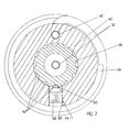
- a travelling mold 10 of the re-circulating bypartite type employed in those machines known as corrugators is formed of two sets of moldblocks 12 that travel on respective endless paths and co-operate along a forward run of each path to define a corrugated mold cavity 14.
- a die 16 extends into the upstream end of the cavity 14. It has an upstream die gap 18 through which a tube 20 of thermoplastic material is extended.
- the tube 20 is molded into the corrugated cavity using either internal air pressure or an external vacuum applied through appropriate openings formed in the moldblocks 12.
- the die 16 also has a downstream die gap 22 for extruding a second tube 24 of thermoplastic material into the first tube and over a cold plug 26 which presses the inner tube against the outer to fuse the two tubes into a double walled pipe 28 with an outer corrugated wall and an inner smooth wall.
- a machine of this type and its operation are described in somewhat greater detail in Canadian Patent Application 405,321 referred to above.
- the mold cavity 14 contains a calibrator 30 for controlling the final configuration of the inner wall and for cooling the formed pipe.
- the calibrator includes a tube 32 wound into a helical configuration on a carrier 34.
- the carrier 34 is connected to the die by a die extension 36 extending downstream from the cold plug 26 at the downstream end of the carrier 34 is a small diameter core extension 38 that carries a bushing 40.
- a downstream end section 42 of the tube 32 extends through an axial bore in the bushing 40 as shown in Figures 1 and 2 and then through a U - shaped bend to extend along the hollow centre of the carrier 34.
- the tube 32 extends through a radial bore (not shown) in the carrier 34.
- the two ends of the tube 32 are connected to coolant lines running along the centre of the die 16 and thench to an external source of fluid coolant.
- the bushing 40 is connected to the core extension 38 by a ball detent 44.
- the detent has a carrier 46 that is threaded into a radial bore 48 in the bushing 40, and a ball 50 that projects from the inner end of the carrier 46 to engage any one of several concave sockets 52 spaced around the carrier extension 38.
- the ball 50 may be pushed into the carrier 46 against the biasing force of a spring (not shown) contained within the carrier.
- a spring not shown
- the ball is cammed into the carrier, out of the socket 52 that it is engaging, so that the bushing may be rotated to a new position where it will be held in place by engagement of the ball 50 in another of the sockets 52.
- This rotation of the bushing 40 will either wind up or unwind the coiled part of the tube 32 to contract or expand the coil and allow adjustment of its diameter.
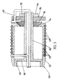
- this drawing illustrates a calibrator with a self-centering carrier 60.
- the carrier includes a central core tube 62 with an external thread 64 at the downstream end and a circular flange 66 adjacent the upstream end.
- the flange 66 carries an internally threaded cylindrical flange 68 that is used to secure the core tube to the die 16.
- a support cylinder 70 surrounds the core tube 62.
- a helical groove 72 in the outer surface of the cylinder carries the coil of tube 32.
- An annular flange 74 at the downstream end of the support cylinder 70 engages the convex upstream face of a plug 76 mounted on the core tube 62.
- the flange 74 rides on the convex face of the plug 76 to center the cylinder 70 on the plug.
- the upstream end of tube 32 extends through radial bores in the cylinder 70 and the core tube 62.
- the end section 42 of tube 32 extends through an axial bore in a bushing 78 that is threaded onto the downstream end of tube 62.
- the end section 42 of the tube 32 is then formed into a U - shaped bend and passes through the center of core tube 62.
- the two ends of the tube 32 extend through the core tube 62 to the upstream end where they are connected to appropriate coolant lines passing through the centre of die 16.
- the support cylinder 70 is dynamically centered inside the pipe by engagement of the convex surface of the plug 76 with the annular flange 74.
- the diameter of the helical core formed by the tube 32 may be adjusted by rotating the bushing 78 on the core tube 62.
- a locknut 79 fixes the bushing 78 in place.
- FIGS 4 and 5 illustrate a calibrator carrier that is expandable and contractable to adjust the diameter of the coils of tube 32.
- the carrier 80 has a core tube 82 that is threaded over a substantial length adjacent its downstream end.
- Surrounding the core tube 82 is a support cylinder 84 divided into plural axial segments 86.
- the segments ride on the tapered faces of respective tapered plugs 88 threaded onto the core tube 82.
- Counter nuts 90 lock the plugs 88 in place on the core tube.
- the resilience of the tube coils retains the segments 86 in place on the plugs 88. If the plugs are brought towards one another, the segments ride along their tapered faces to expand the support cylinder and increase the diameter of the coils of tube 32. Conversely, the diameter may be reduced by separating the plugs 88.
- the present invention is not only applicable to corrugators having recirculating bipartite molds but in general to any apparatus having a travelling mold cavity.
Landscapes
- Engineering & Computer Science (AREA)
- Mechanical Engineering (AREA)
- Manufacturing & Machinery (AREA)
- Extrusion Moulding Of Plastics Or The Like (AREA)
- Blow-Moulding Or Thermoforming Of Plastics Or The Like (AREA)
- Shaping Of Tube Ends By Bending Or Straightening (AREA)
- Radiation Pyrometers (AREA)
- Testing Or Calibration Of Command Recording Devices (AREA)
Applications Claiming Priority (2)
| Application Number | Priority Date | Filing Date | Title |
|---|---|---|---|
| CA429064 | 1983-05-27 | ||
| CA000429064A CA1194663A (en) | 1983-05-27 | 1983-05-27 | Calibrator for use in the manufacture of double walled thermoplastic pipe |
Publications (2)
| Publication Number | Publication Date |
|---|---|
| EP0128366A1 true EP0128366A1 (de) | 1984-12-19 |
| EP0128366B1 EP0128366B1 (de) | 1987-03-11 |
Family
ID=4125337
Family Applications (1)
| Application Number | Title | Priority Date | Filing Date |
|---|---|---|---|
| EP84105299A Expired EP0128366B1 (de) | 1983-05-27 | 1984-05-10 | Kalibriervorrichtung zum Herstellen eines doppelwandigen, thermoplastischen Kunststoffrohres |
Country Status (8)
| Country | Link |
|---|---|
| US (1) | US4555230A (de) |
| EP (1) | EP0128366B1 (de) |
| JP (1) | JPS59227424A (de) |
| KR (1) | KR860001135B1 (de) |
| AU (1) | AU557444B2 (de) |
| CA (1) | CA1194663A (de) |
| DE (1) | DE3462589D1 (de) |
| NO (1) | NO842100L (de) |
Families Citing this family (10)
| Publication number | Priority date | Publication date | Assignee | Title |
|---|---|---|---|---|
| US5186878A (en) * | 1989-01-16 | 1993-02-16 | Corma Inc. | Improvements relating to cooling plugs in thermoplastic pipe forming apparatus and process |
| US5296188A (en) * | 1992-01-14 | 1994-03-22 | Corma, Inc. | Methods for forming tubing utilizing suction and pneumatic pressure at the surface of the cooling plug |
| US5531583A (en) * | 1993-04-15 | 1996-07-02 | Cullom Machine Tool & Die, Inc. | Vacuum mold blocks with cooling for corrugated tubing |
| JPH10697A (ja) * | 1996-06-14 | 1998-01-06 | Toutaku Kogyo Kk | 合成樹脂ホースとその製造方法 |
| JP3854228B2 (ja) * | 2001-03-02 | 2006-12-06 | ルプケ,マンフレッド エー.,エー. | 接続スリーブを有する二重壁熱可塑性チューブを製造する方法及び装置 |
| DE10335518A1 (de) * | 2003-07-31 | 2005-02-24 | Manfred Arno Alfred Thornhill Lupke | Vorrichtung zur Herstellung eines doppelwandigen thermoplastischen Rohrs mit einer Rohrmuffe |
| CA2450560C (en) * | 2003-11-24 | 2006-05-16 | Manfred A. A. Lupke | Pipe molding system with vacuum and temperature controls of cooling plugs |
| US7205479B2 (en) * | 2005-02-14 | 2007-04-17 | Panduit Corp. | Enhanced communication cable systems and methods |
| CA2588058C (en) * | 2007-05-08 | 2014-07-15 | Stefan A. Lupke | Alignable cooling plug for extruder |
| CN111421780A (zh) * | 2020-03-13 | 2020-07-17 | 联塑科技发展(贵阳)有限公司 | 一种可变径的定径套 |
Citations (6)
| Publication number | Priority date | Publication date | Assignee | Title |
|---|---|---|---|---|
| US3907961A (en) * | 1974-01-28 | 1975-09-23 | Phillips Petroleum Co | Flexible cylinder for cooling an extruded pipe |
| GB1432886A (en) * | 1974-03-22 | 1976-04-22 | Hegler Wilhelm | Extrusion apparatus scanning elect |
| GB1439294A (en) * | 1974-03-22 | 1976-06-16 | Hegler Wilhelm | Method of and apparatus for extruding tubes |
| CA1083765A (en) * | 1976-12-01 | 1980-08-19 | Gerd P. H. Lupke | Apparatus for producing thermoplastic tubing |
| US4226580A (en) * | 1977-02-07 | 1980-10-07 | Lupke Gerd Paul Heinrich | Apparatus for producing thermoplastic tubing |
| EP0096957A2 (de) * | 1982-06-16 | 1983-12-28 | Manfred Arno Alfred Lupke | Vorrichtung zur Herstellung von Mehrschichtrohren aus thermoplastischem Werkstoff |
Family Cites Families (6)
| Publication number | Priority date | Publication date | Assignee | Title |
|---|---|---|---|---|
| DE1221429B (de) * | 1963-08-26 | 1966-07-21 | Fraenk Isolierrohr & Metall | Vorrichtung zum Erzeugen von Rohren aus vorzugsweise thermoplastischem Kunststoff mit quer zur Umfangsrichtung wellenfoermig verlaufender Wandung |
| US3247548A (en) * | 1962-05-28 | 1966-04-26 | Roehr Metals & Plastics Compan | Apparatus for making a molded article |
| AT325299B (de) * | 1967-02-27 | 1975-10-10 | Hegler Wilhelm | Vorrichtung zur herstellung von rohren aus thermoplastischem kunststoff |
| US4233020A (en) * | 1979-03-13 | 1980-11-11 | Owens-Corning Fiberglas Corporation | Collapsible mandrel |
| US4352470A (en) * | 1981-03-27 | 1982-10-05 | Textron, Inc. | Combined payoff and winder for strip rolling mills |
| EP0081298A1 (de) * | 1981-12-04 | 1983-06-15 | Manfred Arno Alfred Lupke | Vorrichtung zum Herstellen von mehrwandigen Röhren aus thermoplastischem Material |
-
1983
- 1983-05-27 CA CA000429064A patent/CA1194663A/en not_active Expired
-
1984
- 1984-03-07 US US06/587,139 patent/US4555230A/en not_active Expired - Lifetime
- 1984-03-15 AU AU25661/84A patent/AU557444B2/en not_active Ceased
- 1984-04-21 KR KR1019840002111A patent/KR860001135B1/ko not_active Expired
- 1984-05-10 DE DE8484105299T patent/DE3462589D1/de not_active Expired
- 1984-05-10 EP EP84105299A patent/EP0128366B1/de not_active Expired
- 1984-05-22 JP JP59101887A patent/JPS59227424A/ja active Pending
- 1984-05-25 NO NO842100A patent/NO842100L/no unknown
Patent Citations (6)
| Publication number | Priority date | Publication date | Assignee | Title |
|---|---|---|---|---|
| US3907961A (en) * | 1974-01-28 | 1975-09-23 | Phillips Petroleum Co | Flexible cylinder for cooling an extruded pipe |
| GB1432886A (en) * | 1974-03-22 | 1976-04-22 | Hegler Wilhelm | Extrusion apparatus scanning elect |
| GB1439294A (en) * | 1974-03-22 | 1976-06-16 | Hegler Wilhelm | Method of and apparatus for extruding tubes |
| CA1083765A (en) * | 1976-12-01 | 1980-08-19 | Gerd P. H. Lupke | Apparatus for producing thermoplastic tubing |
| US4226580A (en) * | 1977-02-07 | 1980-10-07 | Lupke Gerd Paul Heinrich | Apparatus for producing thermoplastic tubing |
| EP0096957A2 (de) * | 1982-06-16 | 1983-12-28 | Manfred Arno Alfred Lupke | Vorrichtung zur Herstellung von Mehrschichtrohren aus thermoplastischem Werkstoff |
Also Published As
| Publication number | Publication date |
|---|---|
| AU557444B2 (en) | 1986-12-18 |
| US4555230A (en) | 1985-11-26 |
| JPS59227424A (ja) | 1984-12-20 |
| CA1194663A (en) | 1985-10-08 |
| DE3462589D1 (en) | 1987-04-16 |
| KR840008779A (ko) | 1984-12-19 |
| NO842100L (no) | 1984-11-28 |
| AU2566184A (en) | 1984-11-29 |
| KR860001135B1 (ko) | 1986-08-16 |
| EP0128366B1 (de) | 1987-03-11 |
Similar Documents
| Publication | Publication Date | Title |
|---|---|---|
| JPH0520515Y2 (de) | ||
| EP0191911B1 (de) | Koextrusionsvorrichtung und Verfahren | |
| US4555230A (en) | Calibrator for use in the manufacture of double walled thermoplastic pipe | |
| EP0670768B1 (de) | Extrudereinrichtung mit mitteln zur anpassung des abgabenendes einer extrusionsdüse relativ zu einem extruder zur ausrichtung einer stromabwärts liegenden vorrichtung | |
| US6705851B2 (en) | Extrusion molding apparatus for a thin tube | |
| JPH0661820B2 (ja) | 継目なしプラスチツク・パイプを製造する装置に使用される押出加工金型 | |
| CN1007139B (zh) | 双层塑料管的挤压模 | |
| KR100431365B1 (ko) | 파이프와같은플라스틱스트링을압출가공하는기계용의관형캘리브레이션장치 | |
| ES2016775A4 (es) | Procedimiento para la fabricacion de un tubo de plastico termoplastico con armazon en espiral | |
| US2465482A (en) | Extruding apparatus | |
| EP0846547B1 (de) | Verfahren und Vorrichtung zum kontinuierlichen Kranzen von thermoplastischen, schrumpffähigen Schlauchhüllen | |
| JP2012101539A (ja) | 熱可塑性物質製パイプを製造するための装置 | |
| US6250908B1 (en) | Conduit-making apparatus with a variable diameter winding drum | |
| KR920006237A (ko) | 실리카 유리 광 도파관 예비성형품 제조방법 | |
| CN217514500U (zh) | 一种可变径定径套 | |
| US6209607B1 (en) | Conduit-making apparatus with a multiple diameter winding drum | |
| CN110774564B (zh) | 一种橡胶挤出在线连续包布模头 | |
| RU2015024C1 (ru) | Способ изготовления шин | |
| CN206536862U (zh) | 一种波纹管及波纹管生产设备 | |
| WO2010144860A1 (en) | High output calibrator assembly for pipe extrusion and related methods | |
| JPS582580Y2 (ja) | 補強合成樹脂管の製造装置 | |
| MXPA01008483A (en) | Conduit-making apparatus with a variable-diameter winding drum | |
| SU1500503A1 (ru) | Устройство дл изготовлени двухслойных пластмассовых гофрированных труб | |
| JPS6018333A (ja) | 合成樹脂製螺旋状体の製造方法 | |
| NO793128L (no) | Anordning for ekstrudering av roer. |
Legal Events
| Date | Code | Title | Description |
|---|---|---|---|
| PUAI | Public reference made under article 153(3) epc to a published international application that has entered the european phase |
Free format text: ORIGINAL CODE: 0009012 |
|
| AK | Designated contracting states |
Designated state(s): DE FR GB IT |
|
| 17P | Request for examination filed |
Effective date: 19850214 |
|
| GRAA | (expected) grant |
Free format text: ORIGINAL CODE: 0009210 |
|
| AK | Designated contracting states |
Kind code of ref document: B1 Designated state(s): DE FR GB IT |
|
| REF | Corresponds to: |
Ref document number: 3462589 Country of ref document: DE Date of ref document: 19870416 |
|
| ITF | It: translation for a ep patent filed | ||
| ET | Fr: translation filed | ||
| PLBE | No opposition filed within time limit |
Free format text: ORIGINAL CODE: 0009261 |
|
| STAA | Information on the status of an ep patent application or granted ep patent |
Free format text: STATUS: NO OPPOSITION FILED WITHIN TIME LIMIT |
|
| 26N | No opposition filed | ||
| PG25 | Lapsed in a contracting state [announced via postgrant information from national office to epo] |
Ref country code: GB Effective date: 19890510 |
|
| GBPC | Gb: european patent ceased through non-payment of renewal fee | ||
| PG25 | Lapsed in a contracting state [announced via postgrant information from national office to epo] |
Ref country code: FR Free format text: LAPSE BECAUSE OF NON-PAYMENT OF DUE FEES Effective date: 19900131 |
|
| PG25 | Lapsed in a contracting state [announced via postgrant information from national office to epo] |
Ref country code: DE Effective date: 19900201 |
|
| REG | Reference to a national code |
Ref country code: FR Ref legal event code: ST |