EP0127768A2 - Filtre pour machines à laver le linge - Google Patents
Filtre pour machines à laver le linge Download PDFInfo
- Publication number
- EP0127768A2 EP0127768A2 EP84104867A EP84104867A EP0127768A2 EP 0127768 A2 EP0127768 A2 EP 0127768A2 EP 84104867 A EP84104867 A EP 84104867A EP 84104867 A EP84104867 A EP 84104867A EP 0127768 A2 EP0127768 A2 EP 0127768A2
- Authority
- EP
- European Patent Office
- Prior art keywords
- filter
- housing
- filter body
- closure cap
- opening
- Prior art date
- Legal status (The legal status is an assumption and is not a legal conclusion. Google has not performed a legal analysis and makes no representation as to the accuracy of the status listed.)
- Granted
Links
Images

Classifications
-
- D—TEXTILES; PAPER
- D06—TREATMENT OF TEXTILES OR THE LIKE; LAUNDERING; FLEXIBLE MATERIALS NOT OTHERWISE PROVIDED FOR
- D06F—LAUNDERING, DRYING, IRONING, PRESSING OR FOLDING TEXTILE ARTICLES
- D06F39/00—Details of washing machines not specific to a single type of machines covered by groups D06F9/00 - D06F27/00
- D06F39/10—Filtering arrangements
Definitions
- the present invention relates to a filter for laundry washing machines, particularly laundry washing machines for domestic use.
- the discharge system of a laundry washing machine of this type is usually provided with a filter body removably inserted in a suitable housing formed in a conduit connecting the washing tub of the machine to a discharge pump.
- the filter body extends transversely through the discharge conduit and projects towards the interior of the machine, whereby it is rendered difficult to fully make use of the restricted internal space of the machine, particularly in the case of a laundry washing machine of compact construction, for instance a laundry washing machine of the top loading type.
- the openings of the filter body are not made use of in a uniform manner, resulting in the formation of preferential accumulation zones adjacent the outlet opening of the filter which may thus be obstructed in a short period of time.
- Another disadvantage presented by known filter constructions is that any heavier objects retained by the filter tend to remain in the preferential flow path of the circulating liquid so as to ultimately obstruct the steady outflow of the washing liquid.
- the user may resort to measures effective to reduce the adverse effects of this disadvantage without however eliminating the cause thereof. He may thus retain the machine at a tilted position until the closure cap of the filter housing has been fully removed. Otherwise he may provide a suitable receptacle to be attached below the opening of the filter housing.
- a main object of the invention is therefore the provision of a filter for a laundry washing machine which permits a more rational use to be made of the restricted interior space of the machine.
- a further object of the invention is to provide a filter of the type defined above, the filtering surface of which may be put to use in a more uniform manner, and in which any heavier objects retained therein will not obstruct the preferential flow path of the washing water.
- a still further object of the invention is the avoidance of the undesirable escape of water through the opening of the filter housing each time the closure cap thereof is removed for inspection and cleaning of the filter body.
- a filter for a laundry washing machine comprising a housing disposed in a conduit connecting the washing tub to a discharge pump and adapted to receive therein, through an opening formed in a sidewall of the laundry washing machine, a perforate filter body having one of its ends releasably connected to a closure cap for hermetically closing said housing, while its other end projects freely into the interior of said housing, said filter being characterized in that said housing and said filter body are of arcuate shape extending obliquely downwards from the wall of the laundry washing machine to which they are connected, and in that the lowermost edge of the filter body insertion opening is located at a higher level than the topmost edge of the suction port of the discharge pump.
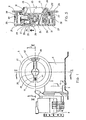
- a filtering unit 4 shown in the drawings is intended, purely by way of example and without being limited thereto, for use in a domestic laundry washing machine 5, and comprises, as shown in fig. 2, an arcuate housing 6 extending obliquely downwards. As shown in fig. 1, housing 6 is provided with an outlet port 7 for connection to a discharge pump 8 and an inlet port 9 for connection to a washing tub 10 by means of a bellows hose 11 fixedly attached thereto in any known manner. Housing 6 is also formed with an inspection opening 12 for the insertion therethrough of a filter body 13 releasably connected to a closure cap 21.
- bellows conduit 11 Adjacent its connection to washing tub 10, bellows conduit 11 is formed with an enlarged-diameter section forming a chamber 14 for collection therein of detergent which would otherwise be lost on the first introduction of water into the washing tub.
- This detergent which would otherwise be retained in an undissolved state within filter 4 and would subsequently be lost on discharge of washing tub 10, is retained in chamber 14 in contact with the lye contained in tub 10 and at the same temperature, so as to be successively dissolved.
- the configuration of the filter 4 according to the invention permits to reduce the dimensions thereof so as to reclaim valuable space for tub 10.
- the filter according to the invention permits the lowermost edge of inspection opening 12 to be located at a higher level than the topmost edge of the intake opening of pump 8.
- Filter body 13 itself of an arcuate shape extending obliquely downwards, presents a pattern of openings 15, 16 of varying size.
- the openings 15 of filter body 13 adjacent outlet opening 7 of filter 4 are smaller than the openings 16 in other portions thereof.
- the cross-sectional shape of filter body 13 is of semicircular configuration opening towards inlet opening 9 connected to washing tub 10.
- the lower end portion of filter body 13 comprises a bottom wall 17 formed with openings 16 and provided with a vertical wall portion 18 adapted to retain within the bottom section of filter body 13 any heavier objects provenient from washing tub 10, such as for instance buttons, coins and the like. In this manner, these objects are prevented from being retained in the preferential flow path and thus from obstructing the discharge flow.
- bottom wall 17 is effective to collect and retain any lose fibers and the like becoming detached from the openings of filetr body 13 and dropping to the bottom portion thereof.
- filter body 13 is closed by a circular wall 19 (fig. 3) provided with a peripheral sealing gasket 20 for hermetically sealing filter housing 6.
- a further advantage of the filter according to the invention derives from the fact that with closure cap 21 closed and tub 10 charged with water, an air cushion is formed in the topmost portion of filter housing 6. The presence of this air cushion causes loose fibers and the like entering filter housing 6 to float up therein and to be retained by openings 16 at a location away from outlet opening 7.
- openings 15 and 16 The varying size of openings 15 and 16 is effective to equilibrate the variations of the turbulences created within filter body 13 during the discharge phase.
- the larger-diameter openings 16 are effective to retain loose fibers and the like in low-turbulence zones, while the smaller openings 15 are adapted to retain such fibers passing through the zone of higher turbulence adjacent intake opening 7 of pump 8.
- the outer face of circular end wall 19 of filter body 13 is formed with a circular ridge 22 of triangular cross-sectional shape and a centrally located engagement recess 23 for a threaded member connecting closure cap 21 to filter body 13.
- Closure cap 21 is formed with a circular through-opening 24 for the passage of engagement recess 23.
- closure cap 21 of the filter 4 is designed so as to prevent its being accidentally or prematurely opened as long as the washing tub is full of hot water.
- closure cap 21 is provided with a locking device cooperating with a projection 27 formed the inner periphery of the opening 12 of filter housing 6.
- the locking device includes an actuating member 28 travelling in a groove 29 in the outer face of closure cap 21 (fig. 1) and foremd with a horizontal leg 30 and a vertical leg 31, and a slide member 32 comprising a forward portion 33 and a rear portion 34 connected to one another by an annular element not shown in the drawings.
- forward portion 33 comprises an indicator arm 35 and a pawl member 36
- rear portion 34 comprises a seat 37 for snap engagement with the suitably shaped vertical leg 31 of actuating member 28, and a stop member 38 adapted to engage the above described projection 27 in the fully closed state of closure cap 21.
- Actuator member 28 is adapted to move slide member 32 against the action of a spring 39 disposed between forward portion 33 and an interior wall surface of closure cap 21.
- sprign 39 is effective to bias slide member 32 and actuator member 28 connected thereto towards an end position defined by groove 29. In this position, stop member 38 engages projection 27 so as to prevent closure cap 21 from being opened.
- the user For opening the filter, the user has to push actuator member 28 in the direction of the arrow shown in fig. 3, whereby slide member 32 is shifted against the action of spring 39 to a position in which stcp member 38 is disengaged from projection 27 while pawl member 36 is engaged with circular ridge 22 for retaining actuator member 28 in the release position.
- closure cap 21 may now be unscrewed, whereupon the play provided between closure cap 21 and engagement recess 23 of edn wall 19 permits pawl member 36 to be released from engagement with circular ridge 22, enabling return spring 39 to return slide member 32, and thus also actuator member 28, to the rest position.
- actuator member 28 Separation of filter body 13 from closure cap 21 requires actuator member 28 to be removed by releasign vertical leg 31 thereof from its snap engagement with seat 37. This gives access to the screw-threaded member for releasing the connection between closure cap 21 and filter body 13.
- Closing of closure cap 21 is carried out by repeating the above steps in reverse sequence without having to actuate actuator member 28.
- an inclined leading flank 42 of stop member 38 permits it to ride over projection 27 (fig. 1).
- stop member 38 is again biased into engagement with projection 27 by return spring 39.
- indicator arm 35 of slide member 32 is provided with a coloured indication tag 40 visible to the user through a small window 41 formed within groove 29 of closure cap 21. Inspection of coloured tag 40 permits the user to make sure that stop memebr 38 is safely engaged with projection 27, preventing closure cap 21 from being accidentally opened.
- the filter 4 permit a substantial reduction of its dimensions enabling a more rational use to be made of the interior space of the washing mashine in favour for instance of the washing tub.
- the design and location of the filter 4 are conducive to a uniform utilization of the entire filtering area according to a lower zone adapted to retain heavier objects, an intermediate zone having smaller openings adjacent the outlet opening of the filter, and an upper zone adapted thanks to the formation of the air cushion therein to collect the major part of loose fibers and the like carried in the water discharged from the washing tub, said air cushion resulting on movement of the washing drum in a back and forth flow of the water containd in the filter, effective to remove loose fibers and the like from the intake zone of the discharge pump and to dissolve any detergent deposits foremd in the filter.
- the filter according to the invention is also effective to definitely solve the problem of the escape of water through the inspection opening, and to eliminate detergent losses by the provision of a decanting chamber in the conduit leading from the washing tub to the filter.
- the variation of the sizes of the openings in the filter body 13 has been established mainly in view of the varying turbulence created in differetn zones of the filter.
- closure cap 21 of the filter 4 is provided with a locking device for reliably preventing the filter from being accidentally opened and for automatically re-establishing the safety condition of the closure cap as the latter is screwed down.
- an indicator means for automatically signalling the re-establishment of the safety condition.
Priority Applications (1)
| Application Number | Priority Date | Filing Date | Title |
|---|---|---|---|
| AT84104867T ATE37208T1 (de) | 1983-05-05 | 1984-04-30 | Filter fuer waschmaschinen. |
Applications Claiming Priority (2)
| Application Number | Priority Date | Filing Date | Title |
|---|---|---|---|
| IT45713/83A IT1195594B (it) | 1983-05-05 | 1983-05-05 | Filtro per lavabiancheria |
| IT4571383 | 1983-05-05 |
Publications (3)
| Publication Number | Publication Date |
|---|---|
| EP0127768A2 true EP0127768A2 (fr) | 1984-12-12 |
| EP0127768A3 EP0127768A3 (en) | 1985-12-11 |
| EP0127768B1 EP0127768B1 (fr) | 1988-09-14 |
Family
ID=11257550
Family Applications (1)
| Application Number | Title | Priority Date | Filing Date |
|---|---|---|---|
| EP84104867A Expired EP0127768B1 (fr) | 1983-05-05 | 1984-04-30 | Filtre pour machines à laver le linge |
Country Status (6)
| Country | Link |
|---|---|
| US (1) | US4566970A (fr) |
| EP (1) | EP0127768B1 (fr) |
| AT (1) | ATE37208T1 (fr) |
| DE (1) | DE3474047D1 (fr) |
| ES (1) | ES287852Y (fr) |
| IT (1) | IT1195594B (fr) |
Cited By (4)
| Publication number | Priority date | Publication date | Assignee | Title |
|---|---|---|---|---|
| DE4444784C2 (de) * | 1993-12-16 | 1999-10-07 | Fagor S Coop Ltda | Deckelverschluß für das Gehäuse einer Entwässerungspumpe |
| EP1849904A1 (fr) * | 2006-04-27 | 2007-10-31 | Electrolux Home Products Corporation N.V. | Appareil d'accès au filtre de vidange à fermeture automatique pour une machine à laver à chargement par le haut |
| EP2385166A1 (fr) * | 2010-05-04 | 2011-11-09 | Electrolux Home Products Corporation N.V. | Machine à laver |
| EP3907322A1 (fr) | 2020-05-06 | 2021-11-10 | Vestel Beyaz Esya Sanayi Ve Ticaret A.S. | Dispositif de lavage comprenant un ensemble de filtration des microfibres |
Families Citing this family (18)
| Publication number | Priority date | Publication date | Assignee | Title |
|---|---|---|---|---|
| IT1192076B (it) * | 1986-04-09 | 1988-03-31 | Zanussi Elettrodomestici | Filtro per macchine lavabiancheria |
| US4806241A (en) * | 1987-05-18 | 1989-02-21 | Holien Dwight H | Overflow lint strainer |
| US4906367A (en) * | 1989-03-27 | 1990-03-06 | Villagomez Timothy A | Lint strainer for washing machine drains |
| JPH05508108A (ja) * | 1991-05-03 | 1993-11-18 | ボコ ゲゼルシャフト ミット ベシュレンクテル ハフツング ウント コムパニー | 水から汚れ粒子を除去するための装置 |
| KR100223415B1 (ko) * | 1997-08-16 | 1999-10-15 | 윤종용 | 세탁기용 이물걸름장치의 역류차단구조 |
| US6253585B1 (en) | 1999-04-20 | 2001-07-03 | Joseph F Wright | Lint filter construction |
| US6210573B1 (en) | 1999-10-01 | 2001-04-03 | Tony D. Marshall | Filtering device for removing lint from the exit hose of a washing machine |
| US7246624B2 (en) * | 2001-09-06 | 2007-07-24 | Metcraft, Inc. | Pot and pan washing machine, components, and methods of washing items |
| KR100441019B1 (ko) * | 2002-07-09 | 2004-07-21 | 삼성전자주식회사 | 식기세척기 |
| KR20050106259A (ko) * | 2004-05-04 | 2005-11-09 | 삼성전자주식회사 | 배수 케이싱을 구비한 세탁기 |
| EP1688530B1 (fr) * | 2005-02-08 | 2013-12-25 | Electrolux Home Products Corporation N.V. | Machine à laver le linge avec un filtre amélioré |
| KR101432585B1 (ko) * | 2007-03-06 | 2014-08-22 | 엘지전자 주식회사 | 이물질 채집 장치 및 이의 청소방법 |
| KR101348718B1 (ko) | 2007-03-06 | 2014-01-10 | 엘지전자 주식회사 | 이물질 채집 장치 및 이를 구비한 세탁기 |
| KR101441917B1 (ko) * | 2007-03-06 | 2014-09-29 | 엘지전자 주식회사 | 이물질 채집 장치 및 이를 적용한 세탁기 |
| KR101360205B1 (ko) * | 2007-03-06 | 2014-02-12 | 엘지전자 주식회사 | 이물질 채집 장치 및 이를 적용한 세탁기 |
| KR101348719B1 (ko) | 2007-03-06 | 2014-01-16 | 엘지전자 주식회사 | 이물질 채집 장치 |
| KR101474501B1 (ko) * | 2008-10-20 | 2014-12-23 | 삼성전자 주식회사 | 배수펌프 및 이를 갖춘 세탁기 |
| US9675230B2 (en) * | 2015-04-03 | 2017-06-13 | Haier Us Appliance Solutions, Inc. | Dishwasher appliance and a method for forming a unitary tub |
Citations (5)
| Publication number | Priority date | Publication date | Assignee | Title |
|---|---|---|---|---|
| US3228525A (en) * | 1962-02-20 | 1966-01-11 | Whirlpool Co | Button trap for a laundry appliance |
| FR1594442A (fr) * | 1967-12-15 | 1970-06-01 | ||
| DE1585818A1 (de) * | 1967-12-09 | 1971-10-07 | Licentia Gmbh | Flusensieb |
| DE1585628B2 (de) * | 1966-01-12 | 1975-03-20 | Congenia S.A., Lugano (Schweiz) | Waschmaschine |
| GB2048962A (en) * | 1979-04-12 | 1980-12-17 | Siltal | Filter unit for washing machines |
Family Cites Families (7)
| Publication number | Priority date | Publication date | Assignee | Title |
|---|---|---|---|---|
| US2103966A (en) * | 1934-12-01 | 1937-12-28 | Thomas W Behan | Washing machine |
| US2287628A (en) * | 1939-10-26 | 1942-06-23 | Gen Electric | Washing apparatus |
| US2413954A (en) * | 1943-12-02 | 1947-01-07 | Jamestown Metal Equipment Comp | Filtering device |
| US2439535A (en) * | 1944-09-16 | 1948-04-13 | Remington Arms Co Inc | Filter |
| US3407633A (en) * | 1966-01-12 | 1968-10-29 | Giambertoni Natale | Washing machine filter |
| US3543542A (en) * | 1969-01-29 | 1970-12-01 | Gen Electric | Self-cleaning filter |
| US3774418A (en) * | 1972-03-28 | 1973-11-27 | Whirlpool Co | Integral self-cleaning filter and side check valve for automatic washer |
-
1983
- 1983-05-05 IT IT45713/83A patent/IT1195594B/it active
-
1984
- 1984-04-26 US US06/604,363 patent/US4566970A/en not_active Expired - Lifetime
- 1984-04-30 AT AT84104867T patent/ATE37208T1/de not_active IP Right Cessation
- 1984-04-30 EP EP84104867A patent/EP0127768B1/fr not_active Expired
- 1984-04-30 DE DE8484104867T patent/DE3474047D1/de not_active Expired
- 1984-05-04 ES ES1984287852U patent/ES287852Y/es not_active Expired
Patent Citations (5)
| Publication number | Priority date | Publication date | Assignee | Title |
|---|---|---|---|---|
| US3228525A (en) * | 1962-02-20 | 1966-01-11 | Whirlpool Co | Button trap for a laundry appliance |
| DE1585628B2 (de) * | 1966-01-12 | 1975-03-20 | Congenia S.A., Lugano (Schweiz) | Waschmaschine |
| DE1585818A1 (de) * | 1967-12-09 | 1971-10-07 | Licentia Gmbh | Flusensieb |
| FR1594442A (fr) * | 1967-12-15 | 1970-06-01 | ||
| GB2048962A (en) * | 1979-04-12 | 1980-12-17 | Siltal | Filter unit for washing machines |
Cited By (5)
| Publication number | Priority date | Publication date | Assignee | Title |
|---|---|---|---|---|
| DE4444784C2 (de) * | 1993-12-16 | 1999-10-07 | Fagor S Coop Ltda | Deckelverschluß für das Gehäuse einer Entwässerungspumpe |
| EP1849904A1 (fr) * | 2006-04-27 | 2007-10-31 | Electrolux Home Products Corporation N.V. | Appareil d'accès au filtre de vidange à fermeture automatique pour une machine à laver à chargement par le haut |
| WO2007124804A1 (fr) * | 2006-04-27 | 2007-11-08 | Electrolux Home Products Corporation N.V. | Appareil à fermeture automatique d'accès au filtre de vidange pour machine à laver à chargement par le haut |
| EP2385166A1 (fr) * | 2010-05-04 | 2011-11-09 | Electrolux Home Products Corporation N.V. | Machine à laver |
| EP3907322A1 (fr) | 2020-05-06 | 2021-11-10 | Vestel Beyaz Esya Sanayi Ve Ticaret A.S. | Dispositif de lavage comprenant un ensemble de filtration des microfibres |
Also Published As
| Publication number | Publication date |
|---|---|
| EP0127768A3 (en) | 1985-12-11 |
| US4566970A (en) | 1986-01-28 |
| EP0127768B1 (fr) | 1988-09-14 |
| ATE37208T1 (de) | 1988-09-15 |
| ES287852U (es) | 1985-12-16 |
| DE3474047D1 (en) | 1988-10-20 |
| IT1195594B (it) | 1988-10-19 |
| ES287852Y (es) | 1986-07-16 |
| IT8345713A1 (it) | 1984-11-05 |
| IT8345713A0 (it) | 1983-05-05 |
Similar Documents
| Publication | Publication Date | Title |
|---|---|---|
| EP0127768A2 (fr) | Filtre pour machines à laver le linge | |
| US7836733B2 (en) | Laundry machine and lint filter thereof | |
| US4485645A (en) | Foreign objects trap for automatic washer | |
| CN107773188B (zh) | 水槽式洗碗机 | |
| US2942444A (en) | Domestic appliance | |
| US2907406A (en) | Dry type air cleaner | |
| KR100820739B1 (ko) | 세탁기 | |
| US2962886A (en) | Washing apparatus having filtering means | |
| US4049551A (en) | Safety device for open receptacle | |
| US2575542A (en) | Lint strainer | |
| US1440192A (en) | Washing machine | |
| US1130430A (en) | Washboiler. | |
| US1390224A (en) | Washing-machine | |
| CN216129842U (zh) | 一种洗衣机 | |
| KR200168048Y1 (ko) | 세탁기 | |
| CN219538198U (zh) | 一种清污分离拖把桶 | |
| CN220158178U (zh) | 水箱组件及清洁装置 | |
| CN114532920B (zh) | 带过滤功能的污水箱及洗地机 | |
| TWI821736B (zh) | 洗劑儲存盒組件及洗衣機 | |
| KR102374000B1 (ko) | 미세섬유 배출방지장치 및 이를 포함하는 세탁기 | |
| KR0131257Y1 (ko) | 드럼세탁기의 세제투입함 걸림구조 | |
| US3111831A (en) | Adjustable post mounted lint filter | |
| JPS5934470Y2 (ja) | 洗濯機のリント捕獲装置 | |
| KR20000045035A (ko) | 세탁기용 오물필터 | |
| KR0119545Y1 (ko) | 배수전 |
Legal Events
| Date | Code | Title | Description |
|---|---|---|---|
| PUAI | Public reference made under article 153(3) epc to a published international application that has entered the european phase |
Free format text: ORIGINAL CODE: 0009012 |
|
| AK | Designated contracting states |
Designated state(s): AT BE CH DE FR GB IT LI LU NL SE |
|
| PUAL | Search report despatched |
Free format text: ORIGINAL CODE: 0009013 |
|
| AK | Designated contracting states |
Designated state(s): AT BE CH DE FR GB IT LI LU NL SE |
|
| 17P | Request for examination filed |
Effective date: 19860321 |
|
| 17Q | First examination report despatched |
Effective date: 19870814 |
|
| GRAA | (expected) grant |
Free format text: ORIGINAL CODE: 0009210 |
|
| AK | Designated contracting states |
Kind code of ref document: B1 Designated state(s): AT BE CH DE FR GB IT LI LU NL SE |
|
| REF | Corresponds to: |
Ref document number: 37208 Country of ref document: AT Date of ref document: 19880915 Kind code of ref document: T |
|
| ITF | It: translation for a ep patent filed |
Owner name: PROPRIA PROTEZIONE PROPR. IND. |
|
| REF | Corresponds to: |
Ref document number: 3474047 Country of ref document: DE Date of ref document: 19881020 |
|
| ET | Fr: translation filed | ||
| PG25 | Lapsed in a contracting state [announced via postgrant information from national office to epo] |
Ref country code: LU Free format text: LAPSE BECAUSE OF NON-PAYMENT OF DUE FEES Effective date: 19890430 |
|
| ITPR | It: changes in ownership of a european patent |
Owner name: OFFERTA DI LICENZA AL PUBBLICO |
|
| PLBE | No opposition filed within time limit |
Free format text: ORIGINAL CODE: 0009261 |
|
| STAA | Information on the status of an ep patent application or granted ep patent |
Free format text: STATUS: NO OPPOSITION FILED WITHIN TIME LIMIT |
|
| 26N | No opposition filed | ||
| PGFP | Annual fee paid to national office [announced via postgrant information from national office to epo] |
Ref country code: AT Payment date: 19900312 Year of fee payment: 7 |
|
| PGFP | Annual fee paid to national office [announced via postgrant information from national office to epo] |
Ref country code: CH Payment date: 19900321 Year of fee payment: 7 |
|
| PGFP | Annual fee paid to national office [announced via postgrant information from national office to epo] |
Ref country code: BE Payment date: 19900327 Year of fee payment: 7 |
|
| PGFP | Annual fee paid to national office [announced via postgrant information from national office to epo] |
Ref country code: LU Payment date: 19900406 Year of fee payment: 7 |
|
| PGFP | Annual fee paid to national office [announced via postgrant information from national office to epo] |
Ref country code: NL Payment date: 19900430 Year of fee payment: 7 |
|
| ITTA | It: last paid annual fee | ||
| PG25 | Lapsed in a contracting state [announced via postgrant information from national office to epo] |
Ref country code: LI Effective date: 19910430 Ref country code: CH Effective date: 19910430 Ref country code: BE Effective date: 19910430 Ref country code: AT Effective date: 19910430 |
|
| BERE | Be: lapsed |
Owner name: INDUSTRIE ZANUSSI S.P.A. Effective date: 19910430 |
|
| PG25 | Lapsed in a contracting state [announced via postgrant information from national office to epo] |
Ref country code: NL Effective date: 19911101 |
|
| NLV4 | Nl: lapsed or anulled due to non-payment of the annual fee | ||
| REG | Reference to a national code |
Ref country code: CH Ref legal event code: PL |
|
| EAL | Se: european patent in force in sweden |
Ref document number: 84104867.1 |
|
| REG | Reference to a national code |
Ref country code: GB Ref legal event code: IF02 |
|
| PGFP | Annual fee paid to national office [announced via postgrant information from national office to epo] |
Ref country code: FR Payment date: 20030310 Year of fee payment: 20 |
|
| PGFP | Annual fee paid to national office [announced via postgrant information from national office to epo] |
Ref country code: GB Payment date: 20030313 Year of fee payment: 20 |
|
| PGFP | Annual fee paid to national office [announced via postgrant information from national office to epo] |
Ref country code: SE Payment date: 20030319 Year of fee payment: 20 |
|
| PGFP | Annual fee paid to national office [announced via postgrant information from national office to epo] |
Ref country code: DE Payment date: 20030324 Year of fee payment: 20 |
|
| PG25 | Lapsed in a contracting state [announced via postgrant information from national office to epo] |
Ref country code: GB Free format text: LAPSE BECAUSE OF EXPIRATION OF PROTECTION Effective date: 20040429 |
|
| REG | Reference to a national code |
Ref country code: GB Ref legal event code: PE20 |
|
| EUG | Se: european patent has lapsed |