EP0127531A1 - Hydraulisches Betätigungssystem für elektrische Schalter - Google Patents
Hydraulisches Betätigungssystem für elektrische Schalter Download PDFInfo
- Publication number
- EP0127531A1 EP0127531A1 EP84401035A EP84401035A EP0127531A1 EP 0127531 A1 EP0127531 A1 EP 0127531A1 EP 84401035 A EP84401035 A EP 84401035A EP 84401035 A EP84401035 A EP 84401035A EP 0127531 A1 EP0127531 A1 EP 0127531A1
- Authority
- EP
- European Patent Office
- Prior art keywords
- accumulator
- circuit
- oil
- pressure
- hydraulic
- Prior art date
- Legal status (The legal status is an assumption and is not a legal conclusion. Google has not performed a legal analysis and makes no representation as to the accuracy of the status listed.)
- Granted
Links
Images

Classifications
-
- H—ELECTRICITY
- H01—ELECTRIC ELEMENTS
- H01H—ELECTRIC SWITCHES; RELAYS; SELECTORS; EMERGENCY PROTECTIVE DEVICES
- H01H33/00—High-tension or heavy-current switches with arc-extinguishing or arc-preventing means
- H01H33/02—Details
- H01H33/28—Power arrangements internal to the switch for operating the driving mechanism
- H01H33/30—Power arrangements internal to the switch for operating the driving mechanism using fluid actuator
- H01H33/34—Power arrangements internal to the switch for operating the driving mechanism using fluid actuator hydraulic
Definitions
- the present invention relates to oleopneumatic controls for electric circuit breakers.
- these commands essentially comprise: a hydraulic actuator for actuating the movable contact of a circuit breaker; one or more high pressure oleopneumatic accumulators, of the order of 200 to 400 bars, a valve supply / purge valve system, which selectively connects the working chamber of the actuator to the accumulator or to a low pressure purge enclosure; and a hydraulic circuit for sending orders controlling the switching, in the feed position or in the purge position, of the aforementioned valve system.
- the hydraulic circuit for sending orders is selectively put under high pressure, to bring the valve system of the jack to the supply position, that is to say to bring the circuit breaker to the on position; or it is selectively vented to return the valve system of the actuator to the purge position, that is to say to return the circuit breaker to the tripped position.
- the hydraulic circuit for sending orders is placed under the control of a so-called "operational block" control station, of well known construction, which, from fugitive electrical engagement or trigger orders acting on two engagement or trigger electro-valves, puts under high pressure or else purges the hydraulic circuit for sending orders.
- the actuator of the moving contactor of the circuit breaker is returned to the position corresponding to the tripping of the circuit breaker, by the elastic tripping means (mechanical or pneumatic spring), the jack being held, in the position corresponding to the engagement of the circuit breaker. , by maintaining the HP in the cylinder's working chamber.
- the elastic tripping means mechanical or pneumatic spring
- the pipes and in particular the pipes for sending orders, have empty volumes of oil or containing emulsified oil.
- the pipe behaves as if it were partially filled with an elastic fluid and the response time to the hydraulic pressurization signal is extended , indefinitely.
- circuit breakers or circuit breaker modules This is particularly important for groups of circuit breakers or circuit breaker modules to be operated simultaneously (circuit breakers on the three phases of a network or circuit breakers connected in series on the same phase).
- the volumes of emulsified oil contained in the pressureless pipes are returned throughout the hydraulic control circuit, as and when all the switching operations, where they can have harmful effects, for example waves pressure or the impossibility of performing hydraulic sequences in series.
- the invention overcomes these latter drawbacks.
- the subject of the invention is an oleopneumatic control of the aforementioned type comprising, in addition, a pressure reducer delivering a reduced pressure PR from the high pressure HP of the accumulator, as well as a compensator accumulator at reduced pressure, of low capacity, compared to that of the HP accumulator, recharged by the regulator and connected to the hydraulic circuit for sending orders from the oleopneumatic control.
- the compensating accumulator is connected to the hydraulic circuit for sending orders in the vicinity of the upstream end of a part of this circuit, considering the direction of circulation of the oil in this part of the circuit when said circuit goes from the "pressurized” situation to the “pressurized” situation.
- the compensating accumulator directly replenishes non-emulsified oil with the precise locations of the circuit where voids or oil emulsions appear, so that the "oil-filled" situation is restored almost instantaneously in the circuit which is ready to receive a new switch-on signal.
- the regulator and the compensating accumulator are adjusted for a reduced pressure of between 2 and 10 bars, or on the order of 20 to 100 times lower than the pressure of the main accumulator.
- a non-return valve is interposed preventing the return of the HP to the compensating accumulator.
- the compensating accumulator has a low capacity compared to the main accumulator.
- This capacity can be for example 100 to 1000 times more low.
- the capacity of the compensating accumulator can be of the order of a few cubic centimeters to a few tens of cubic centimeters, while the capacity of the main HP accumulators is commonly from a few cubic decimetres to a few tens of cubic decimeters.
- the same compensating accumulator can be connected at several points of the circuit, the most likely to give rise to the appearance of an emulsion, or else several compensating accumulators can be provided for the same command.
- Oleopneumatic controls for circuit breakers often include, as is well known, one or more hydraulic relay valves on the hydraulic circuit connecting the "operational block" to the supply / bleed valve system of the jack.
- the compensating accumulator can be connected not only to the regulator, to be recharged by the latter, but also to one of the chambers of at least one of the relay valves receiving the purge oil from the order sending pipe when the latter is "depressurized", whereby the compensating accumulator is also partially recharged by the purge oil discharged during tripping operations.
- the reduced pressure compensator accumulator is preferably a low inertia accumulator, having a response time for the supply of the compensating oil.
- the compensating accumulator is of the membrane type, with a short stroke, the membranes being subjected to the action of a mechanical spring, by means of a support plate.
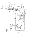
- FIG. 1 shows the essential elements of an oleopneumatic control of known type, for an electric circuit breaker.
- This command includes: a hydraulic cylinder 1 for actuating the movable contact 3 from a circuit breaker to the fixed contact 4; a main high pressure oleopneumatic accumulator 5; a supply / purge valve system 7 for selectively connecting the working chamber 9 of the jack 1 either to a low-pressure enclosure 11, in the tripped position of the circuit breaker shown in FIG. 1, or to the accumulator 5,, for bringing and keep the circuit breaker in the on position.
- the cylinder is returned to the triggered position by permanent elastic means such as a spring 13 or the elastic pressure of the accumulator 5 brought into the upper chamber 9 'of the jack by a pipe 13' indicated in broken lines in FIG. 1.
- the supply / purge system 7 comprises a hydraulic actuator 15 for the supply / purge valve which brings the switching member 17 of the valve into the supply position 17 'when it is subjected to the high hydraulic pressure supplied by a pipe. 19 and returns the switching member 17 to the bleed position shown in solid lines when said actuator is no longer subjected to the high pressure.
- the installation comprises, in a conventional manner, a sending station of order 21, called “operational block”, which can be located at a distance from the circuit breaker, and which comprises a solenoid for engagement 23 and an electrovalve for tripping. 25, which control the switching of a valve 27.
- This valve 27 in the solid line position, connects to a low pressure enclosure 29 the connecting pipe 19 between the operating unit and the valve system 7, while, in position 27 ′, the pipe 19 is connected to the high pressure supplied either by an additional accumulator provided for the operational block, or by the main accumulator 5 which is connected to the operational block by a pipe 31.
- the pipe 19 is put under the high pressure of the main accumulator 5, for example 200 to 400 bars. To bring the circuit breaker into the tripped position, the pipe 19 is vented, substantially at atmospheric pressure. During this maneuver, the oil contained in the line 19 decompresses, as has been explained previously, and at least part of the line 19 is empty of oil or filled with emulsified oil.
- the line 19 will behave as if it were filled with an elastic fluid, so that the response time of l actuator 15 will be considerably increased and variable from one operation to another.
- a "regulator / compensator accumulator” E assembly which comprises a regulator 33 the high pressure side of which is connected to the main accumulator 5 by the pipe 31 and which delivers by its outlet 35 a reduced pressure PR.
- the assembly E also comprises a compensating accumulator 37 at reduced pressure and at low capacity which is recharged with oil at the pressure PR by the pressure reducer and which is connected, by a pipe 39 to the hydraulic circuit for sending orders 19.
- a non-return valve 41 mounted on the pipe 39, prevents the high pressure, present in the pipe 19 in the engaged position of the circuit breaker to gain the reduced pressure portion PR of the hydraulic circuit 33, 35, 37.
- the pipe 39 is connected to the pipe 19 in the vicinity of the upstream end 43 thereof, if one considers the displacement of the oil when the circuit 19 passes from the "pressure” situation to the " off pressure ", this end 43 being the most subject to the phenomenon of lack of oil.
- the line 19 which is partially empty of oil (or filled with emulsified oil) when pressurized, is quickly replenished and replenished with oil in the liquid state, under pressure PR, by the compensating accumulator 37, which is immediately recharged with oil by the regulator 33.
- a check valve 47 calibrated at a pressure slightly higher than the PR pressure.
- the volume of the portions of the hydraulic circuit which empty of oil at the time of depressurization is relatively small, this is why it suffices with a compensating accumulator 37 of small capacity, for example a few cubic centimeters to a few tens of cubic centimeters (about 1000 times less than the capacity of the main battery 5).
- the compensating accumulator 37 it is advantageous for the compensating accumulator 37 to have low inertia, to quickly compensate for the lack of oil. This is why, as will be seen with reference to FIG. 4, a membrane accumulator with a short stroke is preferably chosen, the membrane of which is stressed by a mechanical spring bearing, on a support plate, against the membrane.
- FIG. 2 Another known hydro-pneumatic control system for circuit breaker which includes the same essential elements as that of Figure 1 but in which the connecting pipe 19 between the operating block 21 and the supply-purge valve 7 of the actuator 1 is not only a pipe for sending orders to the valve 7 (by “pressurizing” or “depressurizing”) but also serves as a power line for supplying the working chamber 9 of the actuator 1.
- valve 7 a known valve of the so-called "rapid vent” type, in which the portion 15, forming a piston, of the purge valve 49 constitutes the hydraulic actuator of the valve 7.
- the assembly E comprising the regulator 33 and the compensating accumulator 37, at reduced pressure PR is identical to that which has been described in connection with FIG. 1 and it is preferably connected to the pipe 19 by a pipe 39 opening into the upstream region 43 of the pipe 19.
- a safety valve 51 connected to the portion of the hydraulic circuit 35 which is at the pressure PR.
- This safety valve is calibrated for a pressure slightly higher than PR and protects the assembly E against any abnormal overpressure, for example in the event of leakage of the non-return valve 41.
- pilot valves and relay valves form part of the hydraulic circuit for sending orders and at least some of the chambers which they comprise are also subjected to circulations of emulsified oil or empty volumes of oil.
- circulations of emulsified oil or empty volumes of oil As in the case of the pipes described in connection with FIGS. 1 and 2, there occurs, during the tripping operation, shortages of oil or appearances of emulsified oil in some of the parts of these relay valves or pilot valves and in the pipes on which they communicate, which affects the speed of response at the time of re-pressure.
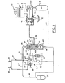
- FIG. 3 shows the essential elements of a conventional oleopneumatic control, similar to that represented in FIG. 1 in that the connecting pipe 19-19 1 , between the operational block 21 and the purge supply valve 7 of the cylinder 1, is only a channel for sending orders ("under pressure” or "unpressurized”).
- the high-speed supply to the jack 1 is provided by the main accumulator 5.
- a purge supply valve 7 is shown, a conventional valve comprising an independent supply valve 53 and a purge valve 55, l the hydraulic actuator 15 of the valve being constituted by the piston-shaped portion of the purge valve 55.
- An auxiliary high-pressure accumulator 5 ′ is also shown supplying the operational block 21, these two accumulators being connected in pressure equilibrium by a low-flow line 56 (shown in broken lines in FIG. 3) and being recharged conventionally by a pump not shown.
- Such a control system conventionally comprises relay valves, of which only one has been shown under the reference 57.
- this relay valve has a high pressure inlet 59, a high pressure outlet 61 connected to the connection pipe 19 ′, a purge outlet 63 and a control input 65 connected to the connection pipe 19 with the block. operational 21.
- the supply 66 and purge 66 ′ valves of the valve 57 are controlled by a pilot cylinder 67.
- the assembly E comprising the regulator 33 and the compensating accumulator at reduced pressure 37 is connected, by a pipe 39, to the chamber purge 69 of the relay valve 57.
- the supply / purge valve of the operational block 21 comes into the purge position 27 shown in solid lines; the pilot cylinder 67 no longer being under pressure, the purge valve 66 'opens and purges the chambers 69-69' and the pipe 19 '.
- the decompression and the circulation of the oil in these volumes produces the phenomena of lack of oil and of emulsion which have been indicated previously.
- the assembly-E replenishes immediately and directly, in oil at the pressure PR, the chambers of the relay valve and the pipe 19 ′, thus ensuring a normal response time to the next engagement order.
- a check valve 47 ′ (similar to the valve 47 in FIGS. 1 and 2), calibrated for a pressure greater than PR, is provided on the purge line 39 ′ connected to the line 39 connecting the assembly E and the chamber of the relay valve 57.
- the chamber 69 is never subjected to high pressure, since, in the engaged position, the valve 66 ′ is closed and isolates the chamber 69. This is why, in this embodiment, there is no provision for a non-return valve on the pipe 39 similar to the non-return valve 41 in FIGS. 1 and 2.
- the chambers of these relay valves equivalent to the chamber 69 can also be replenished with oil at pressure PR by another compensating assembly E or from the assembly E shown in FIG. 3.
- the compensator assembly E is also operating during long periods of immobilization in the triggered position during which any possible return of air is prevented by the supply of oil at reduced pressure PR from the compensator assembly E. It is thus ensured that, from the first engagement maneuver, the response times will be respected.
- FIG. 4 shows an embodiment of the compensating accumulator 37 at reduced pressure PR and at low capacity.
- the accumulator comprises a variable volume oil storage chamber 71 which is closed by a waterproof membrane 73 urged by a spring 75, with the interposition of a support plate 77.
- a connector 81 opening into the chamber 71 is connected to the connection pipe 39 ( Figures 1, 2, 3).
- a vent valve 83 is also provided for the air purge on first filling.
- Such an accumulator has a low inertia, the total stroke of the membrane 73 being for example 5 to 10 mm for a membrane surface of 20 to 40 square centimeters, or a capacity of approximately 10 to 40 cubic centimeters. Thanks to this low inertia, the compensation of empty oil volumes, or filled with emulsified oil, is very fast.
Priority Applications (1)
| Application Number | Priority Date | Filing Date | Title |
|---|---|---|---|
| AT84401035T ATE25786T1 (de) | 1983-05-30 | 1984-05-18 | Hydraulisches betaetigungssystem fuer elektrische schalter. |
Applications Claiming Priority (2)
| Application Number | Priority Date | Filing Date | Title |
|---|---|---|---|
| FR8308910A FR2547108B1 (fr) | 1983-05-30 | 1983-05-30 | Commande oleopneumatique pour disjoncteurs electriques |
| FR8308910 | 1983-05-30 |
Publications (2)
| Publication Number | Publication Date |
|---|---|
| EP0127531A1 true EP0127531A1 (de) | 1984-12-05 |
| EP0127531B1 EP0127531B1 (de) | 1987-03-04 |
Family
ID=9289298
Family Applications (1)
| Application Number | Title | Priority Date | Filing Date |
|---|---|---|---|
| EP84401035A Expired EP0127531B1 (de) | 1983-05-30 | 1984-05-18 | Hydraulisches Betätigungssystem für elektrische Schalter |
Country Status (11)
| Country | Link |
|---|---|
| US (1) | US4669265A (de) |
| EP (1) | EP0127531B1 (de) |
| JP (1) | JPS607024A (de) |
| AT (1) | ATE25786T1 (de) |
| BR (1) | BR8402572A (de) |
| CA (1) | CA1247175A (de) |
| DE (1) | DE3462560D1 (de) |
| FR (1) | FR2547108B1 (de) |
| IN (1) | IN160600B (de) |
| SU (1) | SU1289393A3 (de) |
| UA (1) | UA5570A1 (de) |
Cited By (2)
| Publication number | Priority date | Publication date | Assignee | Title |
|---|---|---|---|---|
| EP0530544A1 (de) * | 1991-09-06 | 1993-03-10 | Sécheron SA | Druckmittelantrieb zum Schliessen und Oeffnen der Kontakte eines Schalters |
| RU2648266C2 (ru) * | 2016-09-12 | 2018-03-23 | Геннадий Феофанович Мамарин | Гидравлический привод для силового высоковольтного выключателя |
Families Citing this family (4)
| Publication number | Priority date | Publication date | Assignee | Title |
|---|---|---|---|---|
| US4785712A (en) * | 1986-05-27 | 1988-11-22 | Mitsubishi Denki Kabushiki Kaisha | Hydraulic operating apparatus for electric circuit breaker |
| CA2127744A1 (en) * | 1993-07-20 | 1995-01-21 | George P. Kokalis | Hydraulic closed loop control system |
| JP2015041555A (ja) * | 2013-08-23 | 2015-03-02 | 株式会社日立製作所 | 遮断器の流体圧駆動装置 |
| KR101515216B1 (ko) * | 2014-11-19 | 2015-04-24 | (주)토피도 티엔에이 | 초대형 유압 브레이커용 실린더 |
Citations (7)
| Publication number | Priority date | Publication date | Assignee | Title |
|---|---|---|---|---|
| US2920607A (en) * | 1956-12-17 | 1960-01-12 | Gen Electric | Hydraulically-actuated operating mechanism for an electric circuit breaker |
| GB842065A (en) * | 1957-10-23 | 1960-07-20 | Gratzmuller Jean Louis | Improvements in or relating to the control of hydraulic actuators |
| FR76484E (fr) * | 1959-11-03 | 1961-10-20 | Comp Generale Electricite | Procédé de commande oléopneumatique d'appareil électrique et application à un disjoncteur |
| FR1311326A (fr) * | 1961-10-25 | 1962-12-07 | Alsthom Cgee | Nouvelles dispositions concernant les commandes hydropneumatiques ou hydrauliques de disjoncteurs électriques |
| FR84825E (fr) * | 1963-10-25 | 1965-04-23 | Comp Generale Electricite | Procédé de commande oléopneumatique d'appareil électrique et application à un disjoncteur |
| FR1482883A (fr) * | 1966-02-28 | 1967-06-02 | Relais hydraulique | |
| DE2828958A1 (de) * | 1978-06-28 | 1980-01-10 | Siemens Ag | Hydraulischer antrieb |
Family Cites Families (6)
| Publication number | Priority date | Publication date | Assignee | Title |
|---|---|---|---|---|
| US2977762A (en) * | 1957-12-09 | 1961-04-04 | Gen Motors Corp | Hydraulic governor pressure control mechanism |
| DE2235074B2 (de) * | 1972-07-12 | 1979-05-17 | Siemens Ag, 1000 Berlin Und 8000 Muenchen | Hydraulische Betätigungsvorrichtung für einen elektrischen Schalter |
| US4213020A (en) * | 1977-10-26 | 1980-07-15 | Westinghouse Electric Corp. | Pneumatic operating mechanism for a circuit-breaker |
| FR2422245A1 (fr) * | 1978-01-04 | 1979-11-02 | Gratzmuller Claude | Systeme de commande hydraulique pour disjoncteurs electriques |
| DE3019626C2 (de) * | 1980-05-22 | 1984-06-20 | Kraftwerk Union AG, 4330 Mülheim | Elektrohydraulischer Stellantrieb für Ventile |
| US4463818A (en) * | 1982-09-07 | 1984-08-07 | Applied Power Inc. | Tilt cab truck in which the cab is partially supported by the tilting cylinder while in the drive position |
-
1983
- 1983-05-30 FR FR8308910A patent/FR2547108B1/fr not_active Expired
-
1984
- 1984-05-16 IN IN355/MAS/84A patent/IN160600B/en unknown
- 1984-05-16 CA CA000454448A patent/CA1247175A/en not_active Expired
- 1984-05-18 AT AT84401035T patent/ATE25786T1/de not_active IP Right Cessation
- 1984-05-18 DE DE8484401035T patent/DE3462560D1/de not_active Expired
- 1984-05-18 EP EP84401035A patent/EP0127531B1/de not_active Expired
- 1984-05-28 SU SU843743761A patent/SU1289393A3/ru active
- 1984-05-28 UA UA3743761A patent/UA5570A1/uk unknown
- 1984-05-29 US US06/614,792 patent/US4669265A/en not_active Expired - Lifetime
- 1984-05-29 BR BR8402572A patent/BR8402572A/pt not_active IP Right Cessation
- 1984-05-30 JP JP59112194A patent/JPS607024A/ja active Granted
Patent Citations (7)
| Publication number | Priority date | Publication date | Assignee | Title |
|---|---|---|---|---|
| US2920607A (en) * | 1956-12-17 | 1960-01-12 | Gen Electric | Hydraulically-actuated operating mechanism for an electric circuit breaker |
| GB842065A (en) * | 1957-10-23 | 1960-07-20 | Gratzmuller Jean Louis | Improvements in or relating to the control of hydraulic actuators |
| FR76484E (fr) * | 1959-11-03 | 1961-10-20 | Comp Generale Electricite | Procédé de commande oléopneumatique d'appareil électrique et application à un disjoncteur |
| FR1311326A (fr) * | 1961-10-25 | 1962-12-07 | Alsthom Cgee | Nouvelles dispositions concernant les commandes hydropneumatiques ou hydrauliques de disjoncteurs électriques |
| FR84825E (fr) * | 1963-10-25 | 1965-04-23 | Comp Generale Electricite | Procédé de commande oléopneumatique d'appareil électrique et application à un disjoncteur |
| FR1482883A (fr) * | 1966-02-28 | 1967-06-02 | Relais hydraulique | |
| DE2828958A1 (de) * | 1978-06-28 | 1980-01-10 | Siemens Ag | Hydraulischer antrieb |
Cited By (2)
| Publication number | Priority date | Publication date | Assignee | Title |
|---|---|---|---|---|
| EP0530544A1 (de) * | 1991-09-06 | 1993-03-10 | Sécheron SA | Druckmittelantrieb zum Schliessen und Oeffnen der Kontakte eines Schalters |
| RU2648266C2 (ru) * | 2016-09-12 | 2018-03-23 | Геннадий Феофанович Мамарин | Гидравлический привод для силового высоковольтного выключателя |
Also Published As
| Publication number | Publication date |
|---|---|
| FR2547108A1 (fr) | 1984-12-07 |
| ATE25786T1 (de) | 1987-03-15 |
| FR2547108B1 (fr) | 1986-07-04 |
| UA5570A1 (uk) | 1994-12-28 |
| CA1247175A (en) | 1988-12-20 |
| SU1289393A3 (ru) | 1987-02-07 |
| DE3462560D1 (en) | 1987-04-09 |
| BR8402572A (pt) | 1985-04-23 |
| US4669265A (en) | 1987-06-02 |
| JPS607024A (ja) | 1985-01-14 |
| EP0127531B1 (de) | 1987-03-04 |
| IN160600B (de) | 1987-07-18 |
| JPH0244093B2 (de) | 1990-10-02 |
Similar Documents
| Publication | Publication Date | Title |
|---|---|---|
| EP0566449B1 (de) | Kombiniertes hydraulisches Höchstlastdrück- und Drückkompensationsventil | |
| FR2548291A1 (fr) | Installation hydraulique comportant deux equipements utilisateurs d'energie hydraulique | |
| CA2270579A1 (fr) | Dispositif de maintien en position de la tige d'un verin hydraulique | |
| EP0127531B1 (de) | Hydraulisches Betätigungssystem für elektrische Schalter | |
| EP3812194B1 (de) | Vorrichtung zur schnellen absenkung eines stromabnehmers, damit ausgerüsteter stromabnehmer, umsetzungs- und verbesserungsverfahren für einen solchen stromabnehmer | |
| BE1006417A3 (fr) | Circuit de recuperation de fluide. | |
| CH627247A5 (de) | ||
| EP0002985B1 (de) | Hydraulisches Betätigungssystem für elektrische Schalter | |
| EP2454489B1 (de) | Hydraulische zufuhr- und rücksetzeinheit für eine hebeanordnung mit zwei separaten simultan betätigten elektrolagern | |
| FR2503214A2 (fr) | Engin de terrassement du type chargeuse | |
| FR2537184A1 (fr) | Procede et circuit hydraulique pour economiser de l'energie lors de l'actionnement d'un cylindre de manoeuvre sur un excavateur hydraulique | |
| FR2666669A1 (fr) | Dispositif d'impression et similaire comprenant un cylindre et un element racleur. | |
| EP0500419A1 (de) | Proportionales Wegeventil und Steuersystem für mehrere hydraulische Verbrauchen, wobei jeder solch ein Ventil beinhaltet | |
| FR2570521A1 (fr) | Dispositif de regulation a deux domaines de pression | |
| EP0459840B1 (de) | Steuereinrichtung für einen doppelt wirkenden Arbeitszylinder | |
| EP0287434A1 (de) | Differentialhydraulischer Kraftzylinder, mit Dämpfungsvorrichtung,zur Steuerung von Leistungsschaltern | |
| FR2509391A1 (fr) | Valve de frein de securite hydraulique | |
| EP0176381B1 (de) | Hydraulisches Hochdruckwegeventil mit Vorsteuerdruckerzeuger | |
| CH627238A5 (de) | ||
| EP0223686B1 (de) | Bremsschaltung eines Hydraulikmotors | |
| FR2837808A1 (fr) | Systeme d'apport d'huile dans la ligne d'equilibrage d'une fleche de grue a portee variable | |
| CA1104907A (fr) | Dispositif de securite pour circuit de commande oleopneumatique | |
| FR2552386A1 (fr) | Valve relais | |
| EP0454510B1 (de) | Steuerkreis für einen hydraulischen, doppelt wirkenden Zylinder und ein Schieberventil für solch einen Kreislauf | |
| FR2842513A1 (fr) | Installation a vanne de commande hydraulique comportant une installation de regulation de debit |
Legal Events
| Date | Code | Title | Description |
|---|---|---|---|
| PUAI | Public reference made under article 153(3) epc to a published international application that has entered the european phase |
Free format text: ORIGINAL CODE: 0009012 |
|
| AK | Designated contracting states |
Designated state(s): AT BE CH DE FR GB IT LI LU NL SE |
|
| 17P | Request for examination filed |
Effective date: 19841112 |
|
| 17Q | First examination report despatched |
Effective date: 19860116 |
|
| ITF | It: translation for a ep patent filed |
Owner name: MANZONI & MANZONI |
|
| GRAA | (expected) grant |
Free format text: ORIGINAL CODE: 0009210 |
|
| AK | Designated contracting states |
Kind code of ref document: B1 Designated state(s): AT BE CH DE FR GB IT LI LU NL SE |
|
| REF | Corresponds to: |
Ref document number: 25786 Country of ref document: AT Date of ref document: 19870315 Kind code of ref document: T |
|
| REF | Corresponds to: |
Ref document number: 3462560 Country of ref document: DE Date of ref document: 19870409 |
|
| PLBE | No opposition filed within time limit |
Free format text: ORIGINAL CODE: 0009261 |
|
| STAA | Information on the status of an ep patent application or granted ep patent |
Free format text: STATUS: NO OPPOSITION FILED WITHIN TIME LIMIT |
|
| 26N | No opposition filed | ||
| ITTA | It: last paid annual fee | ||
| EPTA | Lu: last paid annual fee | ||
| EAL | Se: european patent in force in sweden |
Ref document number: 84401035.5 |
|
| REG | Reference to a national code |
Ref country code: GB Ref legal event code: IF02 |
|
| PGFP | Annual fee paid to national office [announced via postgrant information from national office to epo] |
Ref country code: FR Payment date: 20020405 Year of fee payment: 19 |
|
| PGFP | Annual fee paid to national office [announced via postgrant information from national office to epo] |
Ref country code: SE Payment date: 20020410 Year of fee payment: 19 |
|
| PGFP | Annual fee paid to national office [announced via postgrant information from national office to epo] |
Ref country code: GB Payment date: 20020411 Year of fee payment: 19 |
|
| PGFP | Annual fee paid to national office [announced via postgrant information from national office to epo] |
Ref country code: BE Payment date: 20020412 Year of fee payment: 19 |
|
| PGFP | Annual fee paid to national office [announced via postgrant information from national office to epo] |
Ref country code: AT Payment date: 20020424 Year of fee payment: 19 |
|
| PGFP | Annual fee paid to national office [announced via postgrant information from national office to epo] |
Ref country code: CH Payment date: 20020429 Year of fee payment: 19 |
|
| PGFP | Annual fee paid to national office [announced via postgrant information from national office to epo] |
Ref country code: LU Payment date: 20020430 Year of fee payment: 19 |
|
| PGFP | Annual fee paid to national office [announced via postgrant information from national office to epo] |
Ref country code: NL Payment date: 20020528 Year of fee payment: 19 |
|
| PGFP | Annual fee paid to national office [announced via postgrant information from national office to epo] |
Ref country code: DE Payment date: 20020722 Year of fee payment: 19 |
|
| PG25 | Lapsed in a contracting state [announced via postgrant information from national office to epo] |
Ref country code: LU Free format text: LAPSE BECAUSE OF NON-PAYMENT OF DUE FEES Effective date: 20030518 Ref country code: GB Free format text: LAPSE BECAUSE OF NON-PAYMENT OF DUE FEES Effective date: 20030518 Ref country code: AT Free format text: LAPSE BECAUSE OF NON-PAYMENT OF DUE FEES Effective date: 20030518 |
|
| PG25 | Lapsed in a contracting state [announced via postgrant information from national office to epo] |
Ref country code: SE Free format text: LAPSE BECAUSE OF NON-PAYMENT OF DUE FEES Effective date: 20030519 |
|
| PG25 | Lapsed in a contracting state [announced via postgrant information from national office to epo] |
Ref country code: LI Free format text: LAPSE BECAUSE OF NON-PAYMENT OF DUE FEES Effective date: 20030531 Ref country code: CH Free format text: LAPSE BECAUSE OF NON-PAYMENT OF DUE FEES Effective date: 20030531 Ref country code: BE Free format text: LAPSE BECAUSE OF NON-PAYMENT OF DUE FEES Effective date: 20030531 |
|
| BERE | Be: lapsed |
Owner name: *GRATZMULLER CLAUDE ALAIN Effective date: 20030531 |
|
| PG25 | Lapsed in a contracting state [announced via postgrant information from national office to epo] |
Ref country code: NL Free format text: LAPSE BECAUSE OF NON-PAYMENT OF DUE FEES Effective date: 20031201 |
|
| PG25 | Lapsed in a contracting state [announced via postgrant information from national office to epo] |
Ref country code: DE Free format text: LAPSE BECAUSE OF NON-PAYMENT OF DUE FEES Effective date: 20031202 |
|
| EUG | Se: european patent has lapsed | ||
| GBPC | Gb: european patent ceased through non-payment of renewal fee |
Effective date: 20030518 |
|
| REG | Reference to a national code |
Ref country code: CH Ref legal event code: PL |
|
| PG25 | Lapsed in a contracting state [announced via postgrant information from national office to epo] |
Ref country code: FR Free format text: LAPSE BECAUSE OF NON-PAYMENT OF DUE FEES Effective date: 20040130 |
|
| NLV4 | Nl: lapsed or anulled due to non-payment of the annual fee |
Effective date: 20031201 |
|
| REG | Reference to a national code |
Ref country code: FR Ref legal event code: ST |