EP0127531A1 - Hydraulically operating system for electric circuit breakers - Google Patents
Hydraulically operating system for electric circuit breakers Download PDFInfo
- Publication number
- EP0127531A1 EP0127531A1 EP84401035A EP84401035A EP0127531A1 EP 0127531 A1 EP0127531 A1 EP 0127531A1 EP 84401035 A EP84401035 A EP 84401035A EP 84401035 A EP84401035 A EP 84401035A EP 0127531 A1 EP0127531 A1 EP 0127531A1
- Authority
- EP
- European Patent Office
- Prior art keywords
- accumulator
- circuit
- oil
- pressure
- hydraulic
- Prior art date
- Legal status (The legal status is an assumption and is not a legal conclusion. Google has not performed a legal analysis and makes no representation as to the accuracy of the status listed.)
- Granted
Links
Images

Classifications
-
- H—ELECTRICITY
- H01—ELECTRIC ELEMENTS
- H01H—ELECTRIC SWITCHES; RELAYS; SELECTORS; EMERGENCY PROTECTIVE DEVICES
- H01H33/00—High-tension or heavy-current switches with arc-extinguishing or arc-preventing means
- H01H33/02—Details
- H01H33/28—Power arrangements internal to the switch for operating the driving mechanism
- H01H33/30—Power arrangements internal to the switch for operating the driving mechanism using fluid actuator
- H01H33/34—Power arrangements internal to the switch for operating the driving mechanism using fluid actuator hydraulic
Abstract
Sur les parties (19) du circuit hydraulique de commande, qui sont tantôt sous pression, tantôt hors pression, est raccordé un ensemble E comprenant un détendeur à pression réduite (33) et un accumulateur hydraulique compensateur (37) à faible capacité qui réalimente en huile à pression réduite les portions du circuit manquant d'huile ou remplies d'huile émulsionnée à la suite des manoeuvres de mise hors pression. L'invention permet de réduire les délais de réponse aux ordres d'enclenchment du disjoncteur.On the parts (19) of the hydraulic control circuit, which are sometimes under pressure, sometimes unpressurized, is connected an assembly E comprising a reduced pressure regulator (33) and a low-capacity compensating hydraulic accumulator (37) which replenishes oil at reduced pressure the portions of the circuit lacking oil or filled with emulsified oil following the depressurization operations. The invention makes it possible to reduce the response times to circuit breaker closing orders.
Description
La présente invention concerne les commandes oléopneumatiques pour disjoncteurs électriques.The present invention relates to oleopneumatic controls for electric circuit breakers.
On sait que ces commandes comportent essentiellement : un vérin hydraulique d'actionnement de contact mobile d'un disjoncteur ; un ou plusieurs accumulateurs oléopneumatiques à haute pression, de l'ordre de 200 à 400 bars un système de valve alimentation/purge du vérin, qui raccorde sélectivement la chambre de travail du vérin à l'accumulateur ou à une enceinte basse pression de purge ; et un circuit hydraulique d'envoi d'ordres commandant la commutation, en position alimentation ou en position purge, du système de valve précité.It is known that these commands essentially comprise: a hydraulic actuator for actuating the movable contact of a circuit breaker; one or more high pressure oleopneumatic accumulators, of the order of 200 to 400 bars, a valve supply / purge valve system, which selectively connects the working chamber of the actuator to the accumulator or to a low pressure purge enclosure; and a hydraulic circuit for sending orders controlling the switching, in the feed position or in the purge position, of the aforementioned valve system.
Le circuit hydraulique d'envoi d'ordres est sélectivement mis sous haute pression, pour amener le système de valve du vérin en position alimentation, c'est-à-dire pour amener le disjoncteur en position enclenchée ; ou bien il est sélectivement mis à la purge pour ramener le système de valve du vérin en position purge, c'est-à-dire pour ramener le disjoncteur en position déclenchée.The hydraulic circuit for sending orders is selectively put under high pressure, to bring the valve system of the jack to the supply position, that is to say to bring the circuit breaker to the on position; or it is selectively vented to return the valve system of the actuator to the purge position, that is to say to return the circuit breaker to the tripped position.
Le circuit hydraulique d'envoi d'ordres est placé sous la commande d'un poste de commande dit "bloc opérationnel", de construction bien connue, qui, à partir d'ordres électriques fugitifs d'enclenchement ou de déclenchement agissant sur deux électro-valves d'enclenchement ou de déclenchement, met sous haute pression ou bien à la purge le circuit hydraulique d'envoi d'ordres.The hydraulic circuit for sending orders is placed under the control of a so-called "operational block" control station, of well known construction, which, from fugitive electrical engagement or trigger orders acting on two engagement or trigger electro-valves, puts under high pressure or else purges the hydraulic circuit for sending orders.
Le vérin d' actionnement du contact mobile du disjoncteur est rappelé, vers la position correspondant au déclenchement du disjoncteur, par les moyens élastiques de déclenchement (ressort mécanique ou pneumatique), le vérin étant maintenu, dans la position correspondant à l'enclenchement du disjoncteur, par le maintien de la H.P. dans la chambre de travail du vérin.The actuator of the moving contactor of the circuit breaker is returned to the position corresponding to the tripping of the circuit breaker, by the elastic tripping means (mechanical or pneumatic spring), the jack being held, in the position corresponding to the engagement of the circuit breaker. , by maintaining the HP in the cylinder's working chamber.
Une commande oléopneumatique du type précité est par exemple décrite et représentée dans le livre "Technique de l'Ingénieur" Volume "Electricité", page D 657-5.An oleopneumatic control of the aforementioned type is for example described and represented in the book "Technical Engineering" Volume "Electricity", page D 657-5.
Ainsi qu'il est bien connu, et comme on le voit d'après ce qui précède, un certain nombre des canalisations hydrauliques d'une commande de disjo-c-teur (et, parmi elles les canalisations d'envoi d'ordres) se trouvent alternativement soumises à la H.P. ou bien sont "hors pression" (mise à la purge sensiblement à la pression atmosphérique).As is well known, and as seen from the above, a number of the hydraulic lines of a circuit breaker control (and, among them the lines for sending orders) are alternately subjected to HP or are "unpressurized" (venting substantially at atmospheric pressure).
Etant donné les pressions élevées utilisées (200 à 400 bars), pour lesquelles l'huile se comporte comme un fluide compressible, et étant donné les délais de manoeuvre très courts exigés pour les disjoncteurs, le passage d'une canalisation de la situation "en pression" à la situation "hors pression" donne lieu à des phénomènes de mise en dépression de certains volumes d'huile, du fait de l'inertie des volumes d'huile mis en mouvement rapide (plusieurs dizaines de mètres/seconde qui agissent à la façon d'un piston liquide.Given the high pressures used (200 to 400 bars), for which the oil behaves like a compressible fluid, and given the very short operating times required for circuit breakers, the passage of a pipeline from the situation "into pressure "to the situation" without pressure "gives rise to phenomena of depression of certain volumes of oil, due to the inertia of the volumes of oil set in rapid motion (several tens of meters / second which act at like a liquid piston.
Il en résulte que, en certaines de leurs parties au moins, les canalisations, et notamment les canalisations d'envoi d'ordres, présentent des volumes vides d'huile ou contenant de l'huile émulsionnée.It follows that, in at least some of their parts, the pipes, and in particular the pipes for sending orders, have empty volumes of oil or containing emulsified oil.
Pour la manoeuvre d'enclenchement suivante qui s'effectue par remise en pression de la canalisation précédemment purgée, la canalisation se comporte comme si elle était remplie partiellement d'un fluide élastique et le délai de réponse au signal hydraulique de mise en pression est allongé, de façon indéterminée.For the next engagement maneuver which is carried out by repressurizing the previously purged pipe, the pipe behaves as if it were partially filled with an elastic fluid and the response time to the hydraulic pressurization signal is extended , indefinitely.
Depuis quelques années on recherche des délais de manoeuvre des disjoncteurs de plus en plus courts, de l'ordre de quelques millisecondes entre l'envoi de l'ordre et le début de l'actionnement du vérin, et on recherche encore plus des délais constants reproductibles dans tous les cas de fonctionnement .For a few years, we have been looking for shorter and shorter breaker operating times, of the order of a few milliseconds between sending the order and the start of actuation of the jack, and we have been looking for even more constant times. reproducible in all operating cases.
Ceci est particulièrement important pour les groupes de disjoncteurs ou modules de disjoncteurs devant être actionnés simultanément (disjoncteurs sur les trois phases d'un réseau ou disjoncteurs montés en série sur une même phase).This is particularly important for groups of circuit breakers or circuit breaker modules to be operated simultaneously (circuit breakers on the three phases of a network or circuit breakers connected in series on the same phase).
Ceci est également important dans le cas dit de "l'enclenchement synchrone" dans lequel l'enclenchement doit être réalisé en un point précis de la sinusoïde de la tension du courant, nécessitant de ce fait la connaissance du délai de réponse de la commande.This is also important in the so-called "synchronous engagement" in which the engagement must be carried out at a precise point on the sinusoid of the current voltage, thereby requiring knowledge of the response time of the command.
Dans le cas où un intervalle de temps suffisant s'écoule entre une manoeuvre de déclenchement et la manoeuvre d'enclenchement suivante, un certain équilibre a le temps de se rétablir plus ou moins lentement dans des canalisations d'envoi d'ordres. Mais il est fréquent, dans les installations modernes, que l'intervalle de temps entre l'envoi d'un ordre de déclenchement et l'envoi de l'ordre d'enclenchement suivant ne dépasse pas 3/10è de seconde environ.Il reste alors à ce moment dans les canalisations des volumes vides d'huile ou remplis d'huile émulsionnée, si bien que le délai de réponse peut être doublé, ou même plus, et que les délais de réponse peuvent être très différents entre plusieurs disjoncteurs commandés à partir d'un même signal d'enclenchement.In the event that a sufficient time interval elapses between a triggering maneuver and the next engaging maneuver, a certain equilibrium has the time to recover more or less slowly in the pipes for sending orders. However, it is common in modern installations for the time interval between the sending of a trip order and the sending of the next trip order not to exceed about 3 / 10th of a second. then at this point in the pipes of empty oil or oil filled volumes emulsified, so that the response time can be doubled, or even more, and that the response times can be very different between several circuit breakers controlled from the same trip signal.
C'est en particulier ce défaut que l'invention se propose d'éliminer.It is in particular this defect that the invention proposes to eliminate.
Il est à noter d'autre part que les phénomènes nuisibles décrits ci-dessus, apparaissant dans les canalisations par suite des mises hors pression ou en pression, peuvent provoquer également des rentrées d'air, du fait de joints d'étanchéité qui sont étanches à l'huile mais non étanches à l'air. Dans le cas d'une longue période en position déclenchée, ces rentrées d'air sont nuisibles pour les délais et la reproductibilité des délais des premières manoeuvres d'enclenchement.It should be noted on the other hand that the harmful phenomena described above, appearing in the pipes as a result of pressurization or pressurization, can also cause re-entry of air, due to seals which are tight in oil but not airtight. In the case of a long period in the triggered position, these air inflows are detrimental to the delays and the reproducibility of the delays of the first engagement maneuvers.
Enfin, les volumes d'huile émulsionnée contenus dans les canalisations hors pression sont renvoyés dans tout le circuit de la commande hydraulique, au fur et à mesure de toutes les manoeuvres d'enclenchement, où elles peuvent avoir des effets néfastes, par exemple des ondes de pression importantes ou l'impossibilité d'effectuer des séquences hydrauliques en série.Finally, the volumes of emulsified oil contained in the pressureless pipes are returned throughout the hydraulic control circuit, as and when all the switching operations, where they can have harmful effects, for example waves pressure or the impossibility of performing hydraulic sequences in series.
L'invention permet de remédier à ces derniers inconvénients.The invention overcomes these latter drawbacks.
L'invention a pour objet une commande oléopneumatique du type précité comportant, en plus, un détendeur délivrant une pression réduite PR à partir de la haute pression HP de l'accumulateur, ainsi qu'un accumulateur compensateur à pression réduite, de faible capacité, par rapport à celle de l'accumulateur HP, rechargé par le détendeur et raccordé au circuit hydraulique d'envoi d'ordres de la commande oléopneumatique.The subject of the invention is an oleopneumatic control of the aforementioned type comprising, in addition, a pressure reducer delivering a reduced pressure PR from the high pressure HP of the accumulator, as well as a compensator accumulator at reduced pressure, of low capacity, compared to that of the HP accumulator, recharged by the regulator and connected to the hydraulic circuit for sending orders from the oleopneumatic control.
De préférence l'accumulateur compensateur est raccordé au circuit hydraulique d'envoi d'ordres au voisinage de l'extrémité amont d'une partie de ce circuit en considérant le sens de la circulation de l'huile dans cette partie du circuit lorsque ledit circuit passe de la situation "sous pression" à la situation "hors pression".Preferably the compensating accumulator is connected to the hydraulic circuit for sending orders in the vicinity of the upstream end of a part of this circuit, considering the direction of circulation of the oil in this part of the circuit when said circuit goes from the "pressurized" situation to the "pressurized" situation.
Grâce à cette disposition, l'accumulateur compensateur réalimente directement en huile non émulsionnée les emplacements précis du circuit où apparaissent des vides ou des émulsions d'huile, si bien que la situation "remplie d'huile" est rétablie quasi instantanément dans le circuit qui est prêt à recevoir un nouveau signal d'enclenchement.Thanks to this arrangement, the compensating accumulator directly replenishes non-emulsified oil with the precise locations of the circuit where voids or oil emulsions appear, so that the "oil-filled" situation is restored almost instantaneously in the circuit which is ready to receive a new switch-on signal.
Dans le cas courant d'une commande hydraulique dans laquelle la H.P. fournie par l'accumulateur principal est de l'ordre de 200 à 400 bars, le détendeur et l'accumulateur compensateur sont réglés pour une pression réduite comprise entre 2 et 10 bars, soit de l'ordre de 20 à 100 fois plus réduite que la pression de l'accumulateur principal.In the common case of a hydraulic control in which the HP supplied by the main accumulator is of the order of 200 to 400 bars, the regulator and the compensating accumulator are adjusted for a reduced pressure of between 2 and 10 bars, or on the order of 20 to 100 times lower than the pressure of the main accumulator.
Dans le cas où l'accumulateur compensateur est raccordé, dans toutes les configurations de fonctionnement de l'installation, à une partie du circuit hydraulique susceptible d'être mise sous H.P., on interpose un clapet anti-retour interdisant le retour de la H.P. vers l'accumulateur compensateur.In the case where the compensating accumulator is connected, in all the operating configurations of the installation, to a part of the hydraulic circuit capable of being put under HP, a non-return valve is interposed preventing the return of the HP to the compensating accumulator.
On a indiqué, dans ce qui précède, que l'accumulateur compensateur avait une faible capacité par rapport à l'accumulateur principal. Cette capacité peut être par exemple 100 à 1000 fois plus faible. C'est ainsi que la capacité de l'accumulateur compensateur peut être de l'ordre de quelques centimètres-cube à quelques dizaines de centimètres-cube, alors que la capacité des accumulateurs H.P. principaux est couramment de quelques décimètres-cube à quelques dizaines de décimètres-cube.It has been indicated in the foregoing that the compensating accumulator has a low capacity compared to the main accumulator. This capacity can be for example 100 to 1000 times more low. Thus, the capacity of the compensating accumulator can be of the order of a few cubic centimeters to a few tens of cubic centimeters, while the capacity of the main HP accumulators is commonly from a few cubic decimetres to a few tens of cubic decimeters.
Bien entendu un même accumulateur compensateur peut être raccordé en plusieurs points du circuit, le plus susceptible de donner lieu à l'apparition d'émulsion, ou bien on peut prévoir plusieurs accumulateurs compensateurs, pour une même commande.Of course, the same compensating accumulator can be connected at several points of the circuit, the most likely to give rise to the appearance of an emulsion, or else several compensating accumulators can be provided for the same command.
Les commandes oléopneumatiques pour disjoncteur comportent souvent, comme il est bien connu, une ou plusieurs valves relais hydrauliques sur le circuit hydraulique reliant le "bloc opérationnel" au système de valve alimentation/purge du vérin.Oleopneumatic controls for circuit breakers often include, as is well known, one or more hydraulic relay valves on the hydraulic circuit connecting the "operational block" to the supply / bleed valve system of the jack.
Suivant une forme de réalisation de l'invention, l'accumulateur compensateur peut être raccordé non seulement au détendeur, pour être rechargé par celui-ci, mais également à l'une des chambre de l'une au moins des valves relais recevant l'huile de purge provenant de la canalisation d'envoi d'ordres lorsque celle-ci est mise "hors pression", grâce à quoi l'accumulateur compensateur est également rechargé, partiellement, par l'huile de purge évacuée lors des manoeuvres de déclenchement.According to one embodiment of the invention, the compensating accumulator can be connected not only to the regulator, to be recharged by the latter, but also to one of the chambers of at least one of the relay valves receiving the purge oil from the order sending pipe when the latter is "depressurized", whereby the compensating accumulator is also partially recharged by the purge oil discharged during tripping operations.
L'accumulateur compensateur à pression réduite est de préférence un accumulateur à faible inertie, ayant un délai de réponse pour la fourniture de l'huile de compensation. De préférence, l'accumulateur compensateur est du type à membrane, à faible course, les membranes étant soumises à l'action d'un ressort mécanique, par l'intermédiaire d'une plaque d'appui.The reduced pressure compensator accumulator is preferably a low inertia accumulator, having a response time for the supply of the compensating oil. Preferably, the compensating accumulator is of the membrane type, with a short stroke, the membranes being subjected to the action of a mechanical spring, by means of a support plate.
L'invention sera mieux comprise à la lecture de la description détaillée qui va suivre et à l'examen des dessins annexés qui représentent, à titre d'exemples non limitatifs plusieurs modes de réalisation de l'invention.
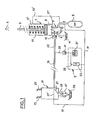
- La figure 1 est une représentation schématique d'une commande oléopneumatique pour disjoncteur équipée d'un système compensateur suivant l'invention.
- La figure 2 est une variante de la figure 1 dans laquelle la canalisation de liaison entre le bloc de commande et le vérin du disjoncteur est, à la fois, une canalisation d'envoi d'ordres hydrauliques et une canalisation de transmission de puissance.
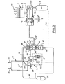
- La figure 3 est une autre variante de la figure 1 dans laquelle le système compensateur suivant l'invention réalimente les valves relais du circuit hydraulique.
- La figure 4 est une vue en coupe d'un accumulateur compensateur à membrane et à ressort.
- FIG. 1 is a schematic representation of an oleopneumatic control for a circuit breaker equipped with a compensating system according to the invention.
- Figure 2 is a variant of Figure 1 in which the connecting pipe between the control unit and the circuit breaker cylinder is, at the same time, a pipe for sending hydraulic orders and a pipe for power transmission.
- FIG. 3 is another variant of FIG. 1 in which the compensating system according to the invention replenishes the relay valves of the hydraulic circuit.
- Figure 4 is a sectional view of a diaphragm and spring compensator accumulator.
On a représenté sur la figure 1 les éléments essentiels d'une commande oléopneumatique de type connu, pour disjoncteur électrique. Cette commande comprend : un vérin hydraulique 1 d'actionnement du contact mobile 3 d'un disjoncteur vers le contact fixe 4 ; un accumulateur oléopneumatique principal haute pression 5 ; un système de valve alimentation/ purge 7 pour raccorder sélectivement la chambre de travail 9 du vérin 1 soit à une enceinte basse pression 11, dans la position déclenchée du disjoncteur représentée sur la figure 1, soit à l'accumulateur 5,,pour amener et maintenir le disjoncteur en position enclenchée. Le vérin est ramené vers la position déclenchée par des moyens élastiques permanents tels qu'un ressort 13 ou la pression élastique de l'accumulateur 5 amenée dans la chambre supérieure 9' du vérin par une canalisation 13' indiquée en traits interrompus sur la figure 1 . Le système alimentation/purge 7 comprend un actionneur hydraulique 15 pour la valve alimentation/purge qui amène l'organe de commutation 17 de la valve dans la position d'alimentation 17' lorsqu'il est soumis à la haute pression hydraulique amenée par une canalisation 19 et ramène l'organe de commutation 17 dans la position de purge représentée en traits pleins lorsque ledit actionneur n'est plus soumis à la haute pression. Enfin l'installation comprend, de façon classique, un poste d'envoi d'ordre 21, dit "bloc opérationnel", qui peut être situé à distance du disjoncteur, et qui comporte une électrovalve d'enclenchement 23 et une électrovalve de déclenche ment 25, lesquelles commandent la commutation d'une valve 27. Cette valve 27, dans la position en traits pleins, raccorde à une enceinte basse pression 29 la canalisation de liaison 19 entre le bloc opérationnel et le système de valve 7, tandis que, dans la position 27', la canalisation 19 est raccordée à la haute pression fournie soit par un accumulateur supplémentaire prévu au bloc opérationnel, soit par l'accumulateur principal 5 qui est raccordé au bloc opérationnel par une canalisation 31.FIG. 1 shows the essential elements of an oleopneumatic control of known type, for an electric circuit breaker. This command includes: a
Le fonctionnement d'une telle installation est bien connu et il suffit de rappeler que, dans le cas représenté sur la figure 1, la canalisation 19, qui peut être de grande longueur, est seulement une canalisation d'envoi d'ordres par "mise en pression" ou "mise hors pression", alors que la puissance hydraulique à grand débit nécessaire à l'alimentation du vérin 1 est fournie directement par l'accumulateur principal 5.The operation of such an installation is well known and it suffices to recall that, in the case shown in FIG. 1, the
Pour amener le disjoncteur en position enclenchée et l'y maintenir, la canalisation 19 est mise sous la haute pression de l'accumulateur principal 5, par exemple 200 à 400 bars. Pour amener le disjoncteur en position déclenchée, la canalisation 19 est mise à la purge, sensiblement à la pression atmosphérique. Au cours de cette manoeuvre, l'huile contenue dans la canalisation 19 se décomprime, comme il a été expliqué précédemment, et une partie au moins de la canalisation 19 se trouve vide d'huile ou garnie d'huile émulsionnée.To bring the circuit breaker into the latched position and keep it there, the
Si l'ordre d'enclenchement suivant, par remise en pression de la canalisation 19, est donné dans un délai bref, la canalisation 19 se comportera comme si elle était remplie d'un fluide élastique, si bien que le délai de réponse de l'actionneur 15 sera considérablement augmenté et variable d'une manoeuvre à l'autre.If the following engagement order, by repressurizing the
Suivant l'invention, on prévoit un ensemble "détendeur/accumulateur compensateur" E qui comprend un détendeur 33 dont le côté haute pression est raccordé à l'accumulateur principal 5 par la canalisation 31 et qui délivre par sa sortie 35 une pression réduite PR. L'ensemble E comprend également un accumulateur compensateur 37 à pression réduite et à faible capacité qui est rechargé en huile à la pression PR par le détendeur et qui est raccordé, par une canalisation 39 au circuit hydraulique d'envoi d'ordres 19.According to the invention, there is provided a "regulator / compensator accumulator" E assembly which comprises a
Un clapet anti-retour 41, monté sur la canalisation 39, empêche la haute pression, présente dans la canalisation 19 en position enclenchée du disjoncteur, de gagner la partie à pression réduite PR du circuit hydraulique 33, 35, 37.A
De préférence, la canalisation 39 est raccordée à la canalisation 19 au voisinage de l'extrémité amont 43 de celle-ci, si on considère le déplacement de l'huile lorsque le circuit 19 passe de la situation "en pression" à la situation "hors pression", cette extrémité 43 étant la plus sujette au phénomène de manque d'huile.Preferably, the
Grâce à l'ensemble E, la canalisation 19, qui se trouve partiellement vide d'huile (ou garnie d'huile émulsionnée) à la mise hors pression, est rapidement réalimentée et regarnie d'huile à l'état liquide, sous la pression PR, par l'accumulateur compensateur 37, lequel est aussitôt rechargé en huile par le détendeur 33.Thanks to the assembly E, the
Pour éviter que, en position déclenchée, l'accumulateur compensateur 37 et le détendeur 33 ne débitent en permanence, on prévoit, sur la canalisation de purge 45 du bloc opérationnel 21, un clapet de retenue 47, taré à une pression légèrement supérieure à la pression PR.To avoid that, in the tripped position, the compensating
Bien entendu, on peut prévoir plusieurs ensembles E identiques, pour réalimenter plusieurs points du circuit hydraulique les plus susceptibles de subir un manque d'huile ou la présence d'huile émulsionnée. On peut encore, à partir d'un ensemble unique E réalimenter plusieurs points du circuit hydraulique.Of course, one can provide several identical sets E, to replenish several points of the hydraulic circuit most likely to suffer from a lack of oil or the presence of emulsified oil. It is also possible, from a single set E, to replenish several points of the hydraulic circuit.
Le volume des portions du circuit hydraulique qui se vident d'huile au moment de la mise hors pression est relativement réduit, c'est pourquoi il suffit d'un accumulateur compensateur 37 de faible capacité, par exemple quelques centimères cube à quelques dizaines de centimètres cube (soit de l'ordre de 1000 fois moins que la capacité de l'accumulateur principal 5).The volume of the portions of the hydraulic circuit which empty of oil at the time of depressurization is relatively small, this is why it suffices with a
D'autre part, on a pu observer qu'il suffisait d'une "Pression Réduite" peu élevée pour réalimenter les portions vides d'huile. C'est ainsi que pour l'accumulateur compensateur 37 et pour le détendeur 33 il suffit de prévoir une pression réduite de l'ordre de 2 à 10 bars, alors que la haute pression de l'accumulateur 5 est de l'ordre de 200 à 400 bars.On the other hand, it has been observed that only a low "Reduced Pressure" is sufficient to refuel the empty portions of oil. Thus, for the compensating
Enfin il est avantageux que l'accumulateur compensateur 37 ait une faible inertie, pour compenser rapidement les manques d'huile. C'est pourquoi, comme on le verra à propos de la figure 4, on choisit de préférence un accumulateur à membrane à faible course, dont la membrane est sollicitée par un ressort mécanique portant, sur un plateau d'appui, contre la membrane.Finally, it is advantageous for the compensating
On a représenté sur la figure 2 un autre système connu de commande hydro-pneumatique pour disjoncteur qui comprend les mêmes éléments essentiels que celui de la figure 1 mais dans lequel la canalisation de liaison 19 entre le bloc opérationnel 21 et la valve alimentation-purge 7 du vérin 1 est non seulement une canalisation d'envoi d'ordres à la valve 7 (par mise "en pression" ou "hors pression") mais également sert de conduite de puissance pour alimenter la chambre de travail 9 du vérin 1.There is shown in Figure 2 another known hydro-pneumatic control system for circuit breaker which includes the same essential elements as that of Figure 1 but in which the connecting
On a représenté à titre d'exemple pour la valve 7, une valve connue du type dit "purgeur rapide", dans laquelle la portion 15, formant piston, du clapet de purge 49 constitue l'actionneur hydraulique de la valve 7.An example is shown for the
L'ensemble E, comprenant le détendeur 33 et l'accumulateur compensateur 37, à pression réduite PR est identique à celui qui a été décrit à propos de la figure 1 et il est de préférence raccordé à la canalisation 19 par une canalisation 39 débouchant dans la région amont 43 de la canalisation 19.The assembly E, comprising the
On peut prévoir en plus une soupape dé sécurité 51 raccordée à la portion de circuit hydraulique 35 qui est à la pression PR. Cette soupape de sécurité est tarée pour une pression légèrement supérieure à PR et protège l'ensemble E contre toute surpression anormale, par exemple en cas de fuite du clapet anti-retour 41.It is also possible to provide a
Il est bien connu que, dans les circuits de commande hydraulique pour disjoncteurs, les valves alimentation/purge finales du ou des vérins, qui sont de grosses sections, ne sont pas commandées directement (comme il a été représenté par mesure de simplification sur les figures 1 et 2) mais par l'intermédiaire de plusieurs valves pilotes et valves relais de sections croissantes.It is well known that, in hydraulic control circuits for circuit breakers, the final supply / purge valves of the jack or jacks, which are large sections, are not directly controlled (as has been shown for simplification in the figures 1 and 2) but via several pilot valves and relay valves of increasing sections.
Ces valves pilotes et valves relais font partie du circuit hydraulique d'envoi d'ordres et certaines au moins des chambres qu'elles comportent sont également soumises à des circulations d'huile émulsionnée ou de volumes vides d'huile. Comme dans le cas des canalisations décrites à propos des figures 1 et 2, il se produit, à la manoeuvre de déclenchement, des manques d'huile ou des apparitions d'huile émulsionnée dans certaines des parties de ces valves relais ou valves pilotes et dans les canalisations sur lesquelles elles communiquent, ce qui nuit à la rapidité de réponse au moment de la remise en pression.These pilot valves and relay valves form part of the hydraulic circuit for sending orders and at least some of the chambers which they comprise are also subjected to circulations of emulsified oil or empty volumes of oil. As in the case of the pipes described in connection with FIGS. 1 and 2, there occurs, during the tripping operation, shortages of oil or appearances of emulsified oil in some of the parts of these relay valves or pilot valves and in the pipes on which they communicate, which affects the speed of response at the time of re-pressure.
Il est donc avantageux de réalimenter en huile à pression réduite certaines au moins des chambres de ces valves.It is therefore advantageous to replenish oil at reduced pressure at least some of the chambers of these valves.
On a représenté sur la figure 3 les éléments essentiels d'une commande oléopneumatique classique, analogue à celle représentée sur la figure 1 en ce sens que la canalisation de liaison 19-191, entre le bloc opérationnel 21 et la valve alimentation purge 7 du vérin 1, est seulement une canalisation d'envoi d'ordres ("en pression" ou "hors pression"). L'alimentation à grand débit du vérin 1 est assurée par l'accumulateur principal 5. On a représenté, en variante, comme valve alimentation purge 7, une valve classique comportant un clapet d'alimentation 53 et un clapet de purge 55 indépendants, l'actionneur hydraulique 15 de la valve étant constitué par la portion en forme de piston du clapet de purge 55.FIG. 3 shows the essential elements of a conventional oleopneumatic control, similar to that represented in FIG. 1 in that the connecting pipe 19-19 1 , between the
On a également représenté un accumulateur auxiliaire haute pression 5' alimentant le bloc opérationnel 21, ces deux accumulateurs étant reliés en équilibre de pression par une conduite à faible débit 56 (représentée en traits interrompus sur la figure 3) et étant rechargés de façon classique par une pompe non représentée.An auxiliary high-
Un tel système de commande comporte, de façon classique, des valves relais, dont on a fait figurer une seule sous la référence 57.Such a control system conventionally comprises relay valves, of which only one has been shown under the
Il suffit de rappeler que cette valve relais comporte une entrée haute pression 59, une sortie haute pression 61 raccordée à la canalisation de liaison 19', une sortie de purge 63 et une entrée de commande 65 reliée à la canalisation de liaison 19 avec le bloc opérationnel 21. Les clapets d'alimentation 66 et de purge 66' de la valve 57 sont commandés par un vérin pilote67.It suffices to recall that this relay valve has a
L'ensemble E comprenant le détendeur 33 et l'accumulateur compensateur à pression réduite 37 est raccordé , par une canalisation 39 , à la chambre de purge 69 de la valve relais 57. Sur un ordre de déclenchement de l'électro-valve 25, la valve alimentation/purge du bloc opérationnel 21 vient dans la position de purge 27 représentée en traits pleins ; le vérin pilote 67 n'étant plus sous pression, le clapet de purge 66' s'ouvre et met à la purge les chambres 69-69' et la canalisation 19'. La décompression et la mise en circulation de l'huile dans ces volumes produit les phénomènes de manque d'huile et d'émulsion qui ont été indiqués précédemment. L'ensemble-E réalimente aussitôt et directement, en huile à la pression PR, les chambres de la valve relais et la canalisation 19', permettant ainsi d'assurer un délai de réponse normale au prochain ordre d'enclenchement.The assembly E comprising the
Un clapet de retenue 47' (analogue au clapet 47 des figures 1 et 2), taré pour une pression supérieure à PR, est prévu sur la canalisation de purge 39' raccordée à la canalisation 39 de liaison entre l'ensemble E et la chambre de la valve relais 57.A
Comme on le voit sur la figure 3, la chambre 69 n'est jamais soumise à la haute pression, puisque, en position enclenchée le clapet 66' est fermé et isole la chambre 69. C'est pourquoi, dans ce mode de réalisation, on ne prévoit pas de clapet anti-retour sur la canalisation 39 analogue au clapet anti-retour 41 des figures 1 et 2.As can be seen in FIG. 3, the
Ceci présente l'avantage que l'accumulateur compensateur à pression réduite 37 est non seulement rechargé par le détendeur 33 mais également partiellement rechargé par l'huile de purge provenant de la décompression de la canalisation 19' à chaque manoeuvre de déclenchement.This has the advantage that the compensated accumulator at
Bien entendu s'il existe une ou plusieurs autres valves relais, par exemple dans le bloc opérationnel 21 à la place de la simple valve alimentation/purge 27-27' qui a été schématiquement représentée, les chambres de ces valves relais équivalentes à la chambre 69 peuvent également être réalimentées en huile à la pression PR par un autre ensemble compensateur E ou à partir de l'ensemble E représenté sur la figure 3.Of course if there are one or more other relay valves, for example in the
Il faut noter que l'ensemble compensateur E suivant l'invention est également opérant pendant les longues périodes d'immobilisation en position déclenchée pendant lesquelles toute rentrée éventuelle d'air est empêchée par l'apport d'huile à pression réduite PR à partir de l'ensemble compensateur E. On est ainsi assuré que, dès la première manoeuvre d'enclenchement, les délais de réponse seront respectés.It should be noted that the compensator assembly E according to the invention is also operating during long periods of immobilization in the triggered position during which any possible return of air is prevented by the supply of oil at reduced pressure PR from the compensator assembly E. It is thus ensured that, from the first engagement maneuver, the response times will be respected.
On a représenté sur la figure 4 un mode de réalisation de l'accumulateur compensateur 37 à pression réduite PR et à faible capacité. L'accumulateur comprend une chambre de stockage d'huile à volume variable 71 qui est fermée par une membrane étanche 73 sollicitée par un ressort 75, avec interposition d'une plaque d'appui 77. Un raccord 81 débouchant dans la chambre 71 est raccordé à la canalisation de raccordement 39 (figures 1, 2, 3). On prévoit également un purgeur 83 pour la purge d'air au premier remplissage. Un tel accumulateur présente une faible inertie, la course totale de la membrane 73 étant par exemple de 5 à 10 mm pour une surface de membrane de 20 à 40 centimètres carrés, soit une capacité d'environ 10 à 40 centimètres cube. Grâce à cette faible inertie, la compensation des volumes vides d'huile, ou garnis d'huile émulsionnée, est très rapide.FIG. 4 shows an embodiment of the compensating
Claims (8)
Priority Applications (1)
| Application Number | Priority Date | Filing Date | Title |
|---|---|---|---|
| AT84401035T ATE25786T1 (en) | 1983-05-30 | 1984-05-18 | HYDRAULIC ACTUATION SYSTEM FOR ELECTRIC SWITCHES. |
Applications Claiming Priority (2)
| Application Number | Priority Date | Filing Date | Title |
|---|---|---|---|
| FR8308910A FR2547108B1 (en) | 1983-05-30 | 1983-05-30 | OLEOPNEUMATIC CONTROL FOR ELECTRIC CIRCUIT BREAKERS |
| FR8308910 | 1983-05-30 |
Publications (2)
| Publication Number | Publication Date |
|---|---|
| EP0127531A1 true EP0127531A1 (en) | 1984-12-05 |
| EP0127531B1 EP0127531B1 (en) | 1987-03-04 |
Family
ID=9289298
Family Applications (1)
| Application Number | Title | Priority Date | Filing Date |
|---|---|---|---|
| EP84401035A Expired EP0127531B1 (en) | 1983-05-30 | 1984-05-18 | Hydraulically operating system for electric circuit breakers |
Country Status (11)
| Country | Link |
|---|---|
| US (1) | US4669265A (en) |
| EP (1) | EP0127531B1 (en) |
| JP (1) | JPS607024A (en) |
| AT (1) | ATE25786T1 (en) |
| BR (1) | BR8402572A (en) |
| CA (1) | CA1247175A (en) |
| DE (1) | DE3462560D1 (en) |
| FR (1) | FR2547108B1 (en) |
| IN (1) | IN160600B (en) |
| SU (1) | SU1289393A3 (en) |
| UA (1) | UA5570A1 (en) |
Cited By (2)
| Publication number | Priority date | Publication date | Assignee | Title |
|---|---|---|---|---|
| EP0530544A1 (en) * | 1991-09-06 | 1993-03-10 | Sécheron SA | Fluid pressure operating means, for opening and closing the contacts of a circuit breaker |
| RU2648266C2 (en) * | 2016-09-12 | 2018-03-23 | Геннадий Феофанович Мамарин | Hydraulic drive for a power high voltage switch |
Families Citing this family (4)
| Publication number | Priority date | Publication date | Assignee | Title |
|---|---|---|---|---|
| US4785712A (en) * | 1986-05-27 | 1988-11-22 | Mitsubishi Denki Kabushiki Kaisha | Hydraulic operating apparatus for electric circuit breaker |
| CA2127744A1 (en) * | 1993-07-20 | 1995-01-21 | George P. Kokalis | Hydraulic closed loop control system |
| JP2015041555A (en) * | 2013-08-23 | 2015-03-02 | 株式会社日立製作所 | Fluid pressure driving device for circuit breaker |
| KR101515216B1 (en) * | 2014-11-19 | 2015-04-24 | (주)토피도 티엔에이 | Sylinder for jumbo hydraulic breaker |
Citations (7)
| Publication number | Priority date | Publication date | Assignee | Title |
|---|---|---|---|---|
| US2920607A (en) * | 1956-12-17 | 1960-01-12 | Gen Electric | Hydraulically-actuated operating mechanism for an electric circuit breaker |
| GB842065A (en) * | 1957-10-23 | 1960-07-20 | Gratzmuller Jean Louis | Improvements in or relating to the control of hydraulic actuators |
| FR76484E (en) * | 1959-11-03 | 1961-10-20 | Comp Generale Electricite | Method of oleopneumatic control of electrical apparatus and application to a circuit breaker |
| FR1311326A (en) * | 1961-10-25 | 1962-12-07 | Alsthom Cgee | New provisions concerning hydropneumatic or hydraulic controls of electrical circuit breakers |
| FR84825E (en) * | 1963-10-25 | 1965-04-23 | Comp Generale Electricite | Method of oleopneumatic control of electrical apparatus and application to a circuit breaker |
| FR1482883A (en) * | 1966-02-28 | 1967-06-02 | Hydraulic relay | |
| DE2828958A1 (en) * | 1978-06-28 | 1980-01-10 | Siemens Ag | Hydraulic actuator for HV power switch - has energy storage piston controlled by spring loaded hollow needle |
Family Cites Families (6)
| Publication number | Priority date | Publication date | Assignee | Title |
|---|---|---|---|---|
| US2977762A (en) * | 1957-12-09 | 1961-04-04 | Gen Motors Corp | Hydraulic governor pressure control mechanism |
| DE2235074B2 (en) * | 1972-07-12 | 1979-05-17 | Siemens Ag, 1000 Berlin Und 8000 Muenchen | Hydraulic actuator for an electrical switch |
| US4213020A (en) * | 1977-10-26 | 1980-07-15 | Westinghouse Electric Corp. | Pneumatic operating mechanism for a circuit-breaker |
| FR2422245A1 (en) * | 1978-01-04 | 1979-11-02 | Gratzmuller Claude | HYDRAULIC CONTROL SYSTEM FOR ELECTRIC CIRCUIT BREAKERS |
| DE3019626C2 (en) * | 1980-05-22 | 1984-06-20 | Kraftwerk Union AG, 4330 Mülheim | Electro-hydraulic actuator for valves |
| US4463818A (en) * | 1982-09-07 | 1984-08-07 | Applied Power Inc. | Tilt cab truck in which the cab is partially supported by the tilting cylinder while in the drive position |
-
1983
- 1983-05-30 FR FR8308910A patent/FR2547108B1/en not_active Expired
-
1984
- 1984-05-16 IN IN355/MAS/84A patent/IN160600B/en unknown
- 1984-05-16 CA CA000454448A patent/CA1247175A/en not_active Expired
- 1984-05-18 AT AT84401035T patent/ATE25786T1/en not_active IP Right Cessation
- 1984-05-18 EP EP84401035A patent/EP0127531B1/en not_active Expired
- 1984-05-18 DE DE8484401035T patent/DE3462560D1/en not_active Expired
- 1984-05-28 UA UA3743761A patent/UA5570A1/en unknown
- 1984-05-28 SU SU843743761A patent/SU1289393A3/en active
- 1984-05-29 BR BR8402572A patent/BR8402572A/en not_active IP Right Cessation
- 1984-05-29 US US06/614,792 patent/US4669265A/en not_active Expired - Lifetime
- 1984-05-30 JP JP59112194A patent/JPS607024A/en active Granted
Patent Citations (7)
| Publication number | Priority date | Publication date | Assignee | Title |
|---|---|---|---|---|
| US2920607A (en) * | 1956-12-17 | 1960-01-12 | Gen Electric | Hydraulically-actuated operating mechanism for an electric circuit breaker |
| GB842065A (en) * | 1957-10-23 | 1960-07-20 | Gratzmuller Jean Louis | Improvements in or relating to the control of hydraulic actuators |
| FR76484E (en) * | 1959-11-03 | 1961-10-20 | Comp Generale Electricite | Method of oleopneumatic control of electrical apparatus and application to a circuit breaker |
| FR1311326A (en) * | 1961-10-25 | 1962-12-07 | Alsthom Cgee | New provisions concerning hydropneumatic or hydraulic controls of electrical circuit breakers |
| FR84825E (en) * | 1963-10-25 | 1965-04-23 | Comp Generale Electricite | Method of oleopneumatic control of electrical apparatus and application to a circuit breaker |
| FR1482883A (en) * | 1966-02-28 | 1967-06-02 | Hydraulic relay | |
| DE2828958A1 (en) * | 1978-06-28 | 1980-01-10 | Siemens Ag | Hydraulic actuator for HV power switch - has energy storage piston controlled by spring loaded hollow needle |
Cited By (2)
| Publication number | Priority date | Publication date | Assignee | Title |
|---|---|---|---|---|
| EP0530544A1 (en) * | 1991-09-06 | 1993-03-10 | Sécheron SA | Fluid pressure operating means, for opening and closing the contacts of a circuit breaker |
| RU2648266C2 (en) * | 2016-09-12 | 2018-03-23 | Геннадий Феофанович Мамарин | Hydraulic drive for a power high voltage switch |
Also Published As
| Publication number | Publication date |
|---|---|
| FR2547108A1 (en) | 1984-12-07 |
| US4669265A (en) | 1987-06-02 |
| BR8402572A (en) | 1985-04-23 |
| CA1247175A (en) | 1988-12-20 |
| EP0127531B1 (en) | 1987-03-04 |
| SU1289393A3 (en) | 1987-02-07 |
| JPS607024A (en) | 1985-01-14 |
| IN160600B (en) | 1987-07-18 |
| JPH0244093B2 (en) | 1990-10-02 |
| UA5570A1 (en) | 1994-12-28 |
| DE3462560D1 (en) | 1987-04-09 |
| FR2547108B1 (en) | 1986-07-04 |
| ATE25786T1 (en) | 1987-03-15 |
Similar Documents
| Publication | Publication Date | Title |
|---|---|---|
| EP0566449A1 (en) | Hydraulic maximum load and pressure compensating valve | |
| FR2548291A1 (en) | HYDRAULIC INSTALLATION COMPRISING TWO EQUIPMENT USING HYDRAULIC ENERGY | |
| CA2270579A1 (en) | Device for holding in position the rod of a pressure cylinder | |
| EP0127531B1 (en) | Hydraulically operating system for electric circuit breakers | |
| EP3812194B1 (en) | Quick descent device for a pantograph, pantograph equipped with same, method for implementing same and method for improving such a pantograph | |
| FR2509831A1 (en) | RE-POSITION CONTROL FOR HYDRAULIC WATER SUPPORT, AS WELL AS HYDRAULIC CONTROL NON-RETURN VALVE | |
| CH627247A5 (en) | ||
| EP0002985B1 (en) | Hydraulic operating system for electric circuit breakers | |
| EP2454489B1 (en) | Supply and resetting hydraulic unit for a lifting assembly with two separate simultaneously actuated powered bearings | |
| FR2503214A2 (en) | FEEDER-TYPE TERRACEMENT ENGINE | |
| FR2537184A1 (en) | HYDRAULIC PROCESS AND CIRCUIT FOR SAVING ENERGY WHEN OPERATING A MANEUVERING CYLINDER ON A HYDRAULIC EXCAVATOR | |
| FR2666669A1 (en) | PRINTING DEVICE AND SIMILAR INCLUDING A CYLINDER AND A SCRAPER. | |
| EP0500419A1 (en) | Proportional valve and control system with a plurality of actuators having each such a valve | |
| EP0187051A1 (en) | Double range pressure regulation device | |
| FR2613785A1 (en) | DIFFERENTIAL HYDRAULIC CYLINDER WITH DAMPING SYSTEM FOR CONTROLLING ELECTRIC CIRCUIT BREAKERS | |
| FR2509391A1 (en) | HYDRAULIC SAFETY BRAKE VALVE | |
| EP0176381B1 (en) | High-pressure hydraulic directional control valve with a pilot pressure generator | |
| CH627238A5 (en) | ||
| EP0223686B1 (en) | Braking circuit for at least one hydraulic motor | |
| FR2711742A1 (en) | Pressure control module in a hydraulic circuit. | |
| FR2837808A1 (en) | SYSTEM FOR SUPPLYING OIL TO THE BALANCING LINE OF A CRANE BOOM WITH VARIABLE RANGE | |
| CA1104907A (en) | Safety device for hydropneumatic control circuit | |
| FR2552386A1 (en) | RELAY VALVE | |
| FR2479358A1 (en) | Mechanical digger lifting jack with safety device - monitors pressure after flexible pipeline section to control automatic non-return valve which can be selectively inhibited | |
| FR2842513A1 (en) | HYDRAULIC CONTROL VALVE SYSTEM COMPRISING A FLOW REGULATION SYSTEM |
Legal Events
| Date | Code | Title | Description |
|---|---|---|---|
| PUAI | Public reference made under article 153(3) epc to a published international application that has entered the european phase |
Free format text: ORIGINAL CODE: 0009012 |
|
| AK | Designated contracting states |
Designated state(s): AT BE CH DE FR GB IT LI LU NL SE |
|
| 17P | Request for examination filed |
Effective date: 19841112 |
|
| 17Q | First examination report despatched |
Effective date: 19860116 |
|
| ITF | It: translation for a ep patent filed |
Owner name: MANZONI & MANZONI |
|
| GRAA | (expected) grant |
Free format text: ORIGINAL CODE: 0009210 |
|
| AK | Designated contracting states |
Kind code of ref document: B1 Designated state(s): AT BE CH DE FR GB IT LI LU NL SE |
|
| REF | Corresponds to: |
Ref document number: 25786 Country of ref document: AT Date of ref document: 19870315 Kind code of ref document: T |
|
| REF | Corresponds to: |
Ref document number: 3462560 Country of ref document: DE Date of ref document: 19870409 |
|
| PLBE | No opposition filed within time limit |
Free format text: ORIGINAL CODE: 0009261 |
|
| STAA | Information on the status of an ep patent application or granted ep patent |
Free format text: STATUS: NO OPPOSITION FILED WITHIN TIME LIMIT |
|
| 26N | No opposition filed | ||
| ITTA | It: last paid annual fee | ||
| EPTA | Lu: last paid annual fee | ||
| EAL | Se: european patent in force in sweden |
Ref document number: 84401035.5 |
|
| REG | Reference to a national code |
Ref country code: GB Ref legal event code: IF02 |
|
| PGFP | Annual fee paid to national office [announced via postgrant information from national office to epo] |
Ref country code: FR Payment date: 20020405 Year of fee payment: 19 |
|
| PGFP | Annual fee paid to national office [announced via postgrant information from national office to epo] |
Ref country code: SE Payment date: 20020410 Year of fee payment: 19 |
|
| PGFP | Annual fee paid to national office [announced via postgrant information from national office to epo] |
Ref country code: GB Payment date: 20020411 Year of fee payment: 19 |
|
| PGFP | Annual fee paid to national office [announced via postgrant information from national office to epo] |
Ref country code: BE Payment date: 20020412 Year of fee payment: 19 |
|
| PGFP | Annual fee paid to national office [announced via postgrant information from national office to epo] |
Ref country code: AT Payment date: 20020424 Year of fee payment: 19 |
|
| PGFP | Annual fee paid to national office [announced via postgrant information from national office to epo] |
Ref country code: CH Payment date: 20020429 Year of fee payment: 19 |
|
| PGFP | Annual fee paid to national office [announced via postgrant information from national office to epo] |
Ref country code: LU Payment date: 20020430 Year of fee payment: 19 |
|
| PGFP | Annual fee paid to national office [announced via postgrant information from national office to epo] |
Ref country code: NL Payment date: 20020528 Year of fee payment: 19 |
|
| PGFP | Annual fee paid to national office [announced via postgrant information from national office to epo] |
Ref country code: DE Payment date: 20020722 Year of fee payment: 19 |
|
| PG25 | Lapsed in a contracting state [announced via postgrant information from national office to epo] |
Ref country code: LU Free format text: LAPSE BECAUSE OF NON-PAYMENT OF DUE FEES Effective date: 20030518 Ref country code: GB Free format text: LAPSE BECAUSE OF NON-PAYMENT OF DUE FEES Effective date: 20030518 Ref country code: AT Free format text: LAPSE BECAUSE OF NON-PAYMENT OF DUE FEES Effective date: 20030518 |
|
| PG25 | Lapsed in a contracting state [announced via postgrant information from national office to epo] |
Ref country code: SE Free format text: LAPSE BECAUSE OF NON-PAYMENT OF DUE FEES Effective date: 20030519 |
|
| PG25 | Lapsed in a contracting state [announced via postgrant information from national office to epo] |
Ref country code: LI Free format text: LAPSE BECAUSE OF NON-PAYMENT OF DUE FEES Effective date: 20030531 Ref country code: CH Free format text: LAPSE BECAUSE OF NON-PAYMENT OF DUE FEES Effective date: 20030531 Ref country code: BE Free format text: LAPSE BECAUSE OF NON-PAYMENT OF DUE FEES Effective date: 20030531 |
|
| BERE | Be: lapsed |
Owner name: *GRATZMULLER CLAUDE ALAIN Effective date: 20030531 |
|
| PG25 | Lapsed in a contracting state [announced via postgrant information from national office to epo] |
Ref country code: NL Free format text: LAPSE BECAUSE OF NON-PAYMENT OF DUE FEES Effective date: 20031201 |
|
| PG25 | Lapsed in a contracting state [announced via postgrant information from national office to epo] |
Ref country code: DE Free format text: LAPSE BECAUSE OF NON-PAYMENT OF DUE FEES Effective date: 20031202 |
|
| EUG | Se: european patent has lapsed | ||
| GBPC | Gb: european patent ceased through non-payment of renewal fee |
Effective date: 20030518 |
|
| REG | Reference to a national code |
Ref country code: CH Ref legal event code: PL |
|
| PG25 | Lapsed in a contracting state [announced via postgrant information from national office to epo] |
Ref country code: FR Free format text: LAPSE BECAUSE OF NON-PAYMENT OF DUE FEES Effective date: 20040130 |
|
| NLV4 | Nl: lapsed or anulled due to non-payment of the annual fee |
Effective date: 20031201 |
|
| REG | Reference to a national code |
Ref country code: FR Ref legal event code: ST |