EP0127451B1 - Automatisches Fokussierungssteuersystem für eine Videokamera - Google Patents
Automatisches Fokussierungssteuersystem für eine Videokamera Download PDFInfo
- Publication number
- EP0127451B1 EP0127451B1 EP84303529A EP84303529A EP0127451B1 EP 0127451 B1 EP0127451 B1 EP 0127451B1 EP 84303529 A EP84303529 A EP 84303529A EP 84303529 A EP84303529 A EP 84303529A EP 0127451 B1 EP0127451 B1 EP 0127451B1
- Authority
- EP
- European Patent Office
- Prior art keywords
- focus control
- automatic focus
- optical
- diaphragm
- sub
- Prior art date
- Legal status (The legal status is an assumption and is not a legal conclusion. Google has not performed a legal analysis and makes no representation as to the accuracy of the status listed.)
- Expired
Links
Images
Classifications
-
- G—PHYSICS
- G02—OPTICS
- G02B—OPTICAL ELEMENTS, SYSTEMS OR APPARATUS
- G02B7/00—Mountings, adjusting means, or light-tight connections, for optical elements
- G02B7/28—Systems for automatic generation of focusing signals
- G02B7/36—Systems for automatic generation of focusing signals using image sharpness techniques, e.g. image processing techniques for generating autofocus signals
- G02B7/38—Systems for automatic generation of focusing signals using image sharpness techniques, e.g. image processing techniques for generating autofocus signals measured at different points on the optical axis, e.g. focussing on two or more planes and comparing image data
-
- H—ELECTRICITY
- H04—ELECTRIC COMMUNICATION TECHNIQUE
- H04N—PICTORIAL COMMUNICATION, e.g. TELEVISION
- H04N23/00—Cameras or camera modules comprising electronic image sensors; Control thereof
- H04N23/60—Control of cameras or camera modules
- H04N23/67—Focus control based on electronic image sensor signals
- H04N23/671—Focus control based on electronic image sensor signals in combination with active ranging signals, e.g. using light or sound signals emitted toward objects
-
- H—ELECTRICITY
- H04—ELECTRIC COMMUNICATION TECHNIQUE
- H04N—PICTORIAL COMMUNICATION, e.g. TELEVISION
- H04N23/00—Cameras or camera modules comprising electronic image sensors; Control thereof
- H04N23/60—Control of cameras or camera modules
- H04N23/67—Focus control based on electronic image sensor signals
- H04N23/673—Focus control based on electronic image sensor signals based on contrast or high frequency components of image signals, e.g. hill climbing method
Definitions
- This invention relates to an automatic focus control system for video cameras and more particularly to a system in which the effective diameter of the diaphragm of an optical sub-system is changed in dependence upon the focused state of the optical main system for detecting the point of focus for the optical main system and the direction in which the main system is defocused.
- FR-A-2494858 discloses an automatic focus control system in accordance with the precharacterising part of claim 1.
- an automatic focus control system for a video camera comprising:
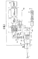
- Figure 1 shows in a schematic block diagram the arrangement of an automatic focus control system as applied to a video camera in which a solid-state iamge sensor formed of charge coupled devices are used for image pickup or shooting.
- a main optical system adapted for guiding the light from an object 1 in the direction of an image pickup surface 10A of the solid-state image sensor and comprised of a focusing lens unit 2, a zoom lens unit 3, a diaphragm 4 and a relay lens unit 5.
- the focus lens unit 2 is driven electrically by an electric motor 60.
- the said main system forms an image of the object on the image pickup surface 10A of the image sensor 10.
- the diaphragm section 4 is provided in an optical path situated intermediate the zoom lens unit 3 and the relay lens unit 5 of the main optical system, said optical path forming a focal system in which the light beam is collimated in the focused state of the main system.
- the diaphragm unit 4 thus situated in the afocal system is used for adjusting the amount of object light incident on the image pickup surface 10A.
- the image output obtained from the solid-state image sensor 10 is taken at a signal output terminal 13 via a buffer amplifier 11 and an automatic gain control circuit 12.
- a beam splitter 8 such as prism is provided in an optical path of the main optical system situated between the zoom lens section 3 and the diaphragm section 4, and thus within the aforementioned afocal system, in such a manner that part of the object light passing through the optical main system is deviated by the prism 8 towards an optical sub-system and thereby directed to a focusing detecting unit 30.
- the sub-system is comprised of a diaphragm unit 21 for changing the amount of the object light arriving at the beam splitter 8, and an image forming lens 22 for converging the object light towards the detecting unit 30, which is comprised of four line sensors 31A, 31B, 32A, 32B each formed by charge-coupled devices.
- the line sensor pair 31A, 31B and the line sensor pair 32A, 32B are mounted parallel to each other in such a manner that the line sensors 31A, 31B, 32A, 32B are positioned at forward positions P F and backward position P B of the optical sub-system on opposite sides of a focused point P o at which a regular object image would be formed.
- the diaphragm unit 21 in the sub-system may be formed by a liquid crystal or the like in which the amount of light passing therethrough may be changed by electrical control signals.
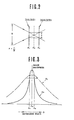
- the object light directed to line sensors 31A, 31B, 32A, 32B is converged by the image forming lens 22 to the shape of a blurred circle with a diameter 6 which is related to the F-number of the diaphragm section 21.
- focused point P o in the markedly defocused state can be detected by making use of the aforementioned evaluation function C s
- the direction in which to effect focus control can be detected by making use of the evaluation function C s in the neighbourhood of the focused point P o and the evaluation function C L for the greatly defocused state providing for a highly accurate focus control.
- an automatic focus control unit 40 On the basis of the outputs S A1 , S A2 resulting from line sensors 31A, 31 B at the above described forward positions, and the outputs S A1 , S A2 resulting from line sensors 32A, 32B at the above described backward positions, an automatic focus control unit 40 detects the focused point and the direction in which to effect focusing by the following operations so as to control the operation of a driving circuit 50 for an electric motor 60 which effects adjustment of the focusing lens unit 2.
- the control unit 40 has a first contrast detecting circuit 41 for effecting contrast detection based on the outputs S A1 , S A2 of the line sensors 31A, 31B arranged at the above described forward positions P F and a second contrast detecting circuit 42 for effecting contrast detection based on the outputs from the line sensors 32A, 32B arranged at the above described backward positions P B .
- the outputs from the contrast detecting circuits 41, 42 are supplied via automatic gain control circuit 43 to a level comparator 44, the outputs of which are used for controlling the operation of a driving circuit 50 of the motor 60.
- a circuit 45 for determining the mismatched or defocused state of the optical main system on the basis of outputs from contrast detecting circuits 41, 42.
- the output from circuit 45 is used for controlling the effective diameter of the diaphragm unit 21 of the optical sub-system.
- the contrast detecting circuits 41, 42 detect the contrast of the object image formed by the object light at the forward position P F , and the contrast of the image formed by the object light at the backward position P B .
- the output signal levels from the dtecting circuits 41, 42 are equal to each other.
- the signal levels from the respective detecting circuits are changed in accordance with the magnitude of the defocused state.
- the operation of the driving circuit 50 is controlled by the error output from the level comparator 44 to permit automatic focus control of the focusing lens unit 2 of the optical main system.
- the circuit 45 acts on the diaphragm unit 21 of the optical sub-system for enhancing the effective diameter to a larger value F L .
- the circuit 45 acts on the section 21 for decreasing the effective diameter to a lesser value F s .
- the effective diameter of the diaphragm section 21 of the optical sub-system is adjusted in such a manner that, at the automatic focus control section 40, when the optical main system is in defocused state, the direction in which to effect focus control can be decided over a wide range and with higher sensitivity on the basis of the above described evaluation function C L for lower sharpness, thus allowing to promptly set the optical main system to the approximately focused state.
- correct focus control can be effected by using the evaluation function for higher sharpness so as to effect focus control accurately.
- the outputs from contrast detecting circuits 21,22 are supplied via automatic gain control circuit 43 to the level comparator 44 for assuring greater precision in the signal comparison operation to be effected at the comparator 44.
- the desired precision may be assured when the light receiving time or charge storage time intervals of the line sensors 31A, 31 B, 32A and 32B are controlled by the output of the circuit 45, in which case the automatic gain control circuit 43 may be omitted.
- the diaphragm section 21 of the optical sub-system may be controlled by binary switching or continuous switching in accordance with contrast and by means of the output from circuit 45.
- the object light volume is controlled at the diaphragm 21 of the optical sub-system, in such a manner that the direction in which to effect focus control may be determined positively over a wider range.
- the automatic focus control of the optical main system can be effected by accurately detecting the focused point P o and the main system may be set to the approximately focused state even in instances where the main system is in extremely defocused state, thus enabling high quality imaging.
- the differential type detction of the automatic focus control section 40 is effective to counteract in-phase noise with resulting increase in the signal to noise ratio and in positive and highly sensitive focus control even in instances where the object is of low contrast or brightness.
Landscapes
- Engineering & Computer Science (AREA)
- Multimedia (AREA)
- Signal Processing (AREA)
- Physics & Mathematics (AREA)
- Computer Vision & Pattern Recognition (AREA)
- General Physics & Mathematics (AREA)
- Optics & Photonics (AREA)
- Automatic Focus Adjustment (AREA)
Claims (4)
Priority Applications (1)
| Application Number | Priority Date | Filing Date | Title |
|---|---|---|---|
| AT84303529T ATE32007T1 (de) | 1983-05-25 | 1984-05-24 | Automatisches fokussierungssteuersystem fuer eine videokamera. |
Applications Claiming Priority (2)
| Application Number | Priority Date | Filing Date | Title |
|---|---|---|---|
| JP58090697A JPS59216380A (ja) | 1983-05-25 | 1983-05-25 | ビデオカメラ |
| JP90697/83 | 1983-05-25 |
Publications (2)
| Publication Number | Publication Date |
|---|---|
| EP0127451A1 EP0127451A1 (de) | 1984-12-05 |
| EP0127451B1 true EP0127451B1 (de) | 1988-01-13 |
Family
ID=14005717
Family Applications (1)
| Application Number | Title | Priority Date | Filing Date |
|---|---|---|---|
| EP84303529A Expired EP0127451B1 (de) | 1983-05-25 | 1984-05-24 | Automatisches Fokussierungssteuersystem für eine Videokamera |
Country Status (7)
| Country | Link |
|---|---|
| US (1) | US4609944A (de) |
| EP (1) | EP0127451B1 (de) |
| JP (1) | JPS59216380A (de) |
| AT (1) | ATE32007T1 (de) |
| AU (1) | AU569742B2 (de) |
| CA (1) | CA1214262A (de) |
| DE (1) | DE3468804D1 (de) |
Families Citing this family (18)
| Publication number | Priority date | Publication date | Assignee | Title |
|---|---|---|---|---|
| JPS6119211U (ja) * | 1984-07-06 | 1986-02-04 | 株式会社 コシナ | オ−トフオ−カス付ズ−ムレンズ |
| JPH0822030B2 (ja) * | 1985-07-10 | 1996-03-04 | 旭精密株式会社 | テレビカメラ用レンズの自動絞り制御装置 |
| US4684995A (en) * | 1986-06-20 | 1987-08-04 | Eastman Kodak Company | Simultaneous exposure/focus control in a video camera using a solid state image sensor |
| EP0266072B1 (de) * | 1986-10-02 | 1993-01-07 | Victor Company Of Japan, Limited | Automatisches Fokussierungsverfahren |
| JPH0771208B2 (ja) * | 1986-11-19 | 1995-07-31 | キヤノン株式会社 | 合焦検出装置 |
| DE3810228A1 (de) * | 1987-03-26 | 1988-10-06 | Asahi Optical Co Ltd | Signalprozessor fuer ein autofokus-videosignal einer elektronisch gesteuerten kamera |
| JPS6461175A (en) * | 1987-08-31 | 1989-03-08 | Asahi Optical Co Ltd | Sensitivity automatic adjusting device for electronic still camera |
| US4838668A (en) * | 1987-10-09 | 1989-06-13 | Eastman Kodak Company | Zoom lens |
| US4757372A (en) * | 1987-10-09 | 1988-07-12 | Eastman Kodak Company | SLR zoom camera |
| US4817922A (en) * | 1987-10-23 | 1989-04-04 | The Goodyear Tire & Rubber Company | Airspring height sensor |
| JPH01218268A (ja) * | 1988-02-26 | 1989-08-31 | Sony Corp | 交換レンズ装置及びカメラ装置 |
| CA1313466C (en) * | 1988-05-11 | 1993-02-09 | Kenichi Kikuchi | Image sensing apparatus having automatic focusing function of automatically matching focus in response to video signal |
| JPH01293771A (ja) * | 1988-05-20 | 1989-11-27 | Victor Co Of Japan Ltd | オートフォーカス方式 |
| DE58906549D1 (de) * | 1988-07-28 | 1994-02-10 | Contraves Ag | Automatische Steuerung der Fokussierung einer Video-Kamera für industrielle/militärische Zwecke. |
| EP0444600B1 (de) * | 1990-02-28 | 1997-08-06 | Sanyo Electric Co., Ltd. | Automatisches Fokussierungsgerät zur automatischen Fokusanpassung in Abhängigkeit von Videosignalen |
| US5170202A (en) * | 1990-07-03 | 1992-12-08 | Eastman Kodak Company | Contrast-based autofocus mechanism |
| JP2003337278A (ja) * | 2002-03-15 | 2003-11-28 | Fuji Photo Optical Co Ltd | レンズシステム |
| US20040130652A1 (en) * | 2002-12-27 | 2004-07-08 | Tadashi Sasaki | Auto focus system |
Family Cites Families (7)
| Publication number | Priority date | Publication date | Assignee | Title |
|---|---|---|---|---|
| DE2705104A1 (de) * | 1977-02-08 | 1978-08-10 | Agfa Gevaert Ag | Fotografische oder kinematografische kamera |
| JPS5548737A (en) * | 1978-10-02 | 1980-04-08 | Konishiroku Photo Ind Co Ltd | Photoelectrically focus detecting device mounted camera |
| JPS55111921A (en) * | 1979-02-14 | 1980-08-29 | Asahi Optical Co Ltd | Focus detector of camera |
| US4420773A (en) * | 1980-06-30 | 1983-12-13 | Nippon Kogaku K.K. | Electronic photographic camera |
| US4414575A (en) * | 1980-11-21 | 1983-11-08 | Hitachi Denshi Kabushiki Kaisha | Autofocus system |
| AU554186B2 (en) * | 1981-10-26 | 1986-08-14 | Sony Corporation | Apparatus for detecting distance to an object |
| US4549801A (en) * | 1983-03-21 | 1985-10-29 | W. Haking Enterprises Limited | Automatic focussing camera with automatic aperture setting |
-
1983
- 1983-05-25 JP JP58090697A patent/JPS59216380A/ja active Pending
-
1984
- 1984-05-18 AU AU28407/84A patent/AU569742B2/en not_active Ceased
- 1984-05-24 US US06/613,571 patent/US4609944A/en not_active Expired - Fee Related
- 1984-05-24 AT AT84303529T patent/ATE32007T1/de not_active IP Right Cessation
- 1984-05-24 DE DE8484303529T patent/DE3468804D1/de not_active Expired
- 1984-05-24 EP EP84303529A patent/EP0127451B1/de not_active Expired
- 1984-05-24 CA CA000455013A patent/CA1214262A/en not_active Expired
Also Published As
| Publication number | Publication date |
|---|---|
| EP0127451A1 (de) | 1984-12-05 |
| DE3468804D1 (en) | 1988-02-18 |
| US4609944A (en) | 1986-09-02 |
| JPS59216380A (ja) | 1984-12-06 |
| ATE32007T1 (de) | 1988-01-15 |
| AU2840784A (en) | 1984-11-29 |
| CA1214262A (en) | 1986-11-18 |
| AU569742B2 (en) | 1988-02-18 |
Similar Documents
| Publication | Publication Date | Title |
|---|---|---|
| EP0127451B1 (de) | Automatisches Fokussierungssteuersystem für eine Videokamera | |
| US6734902B1 (en) | Vibration correcting device | |
| US7405762B2 (en) | Camera having AF function | |
| US4492449A (en) | Apparatus and technique for detecting and controlling the focusing of an optical system by image sharpness and lateral shift techniques | |
| US20080247741A1 (en) | Image-taking apparatus | |
| KR970007469A (ko) | 렌즈 구동 장치 및 이를 이용한 촬상 장치 | |
| US5140357A (en) | Automatic focusing device wherein loop gain is set responsively to variation of magnification | |
| US5995144A (en) | Automatic focusing device using phase difference detection | |
| US5402175A (en) | Automatic focusing device wherein lens movement is controlled in accordance with lens hunting | |
| US5652925A (en) | Image sensor system and auto-focus detection device | |
| US4159169A (en) | Automatic focusing apparatus | |
| JP2737388B2 (ja) | 電子カメラのオートフォーカス装置 | |
| JPH0620265B2 (ja) | 自動焦点調整装置 | |
| JP2000019386A (ja) | カメラ | |
| JP3663850B2 (ja) | 露出制御装置及び露出制御方法 | |
| JPS59221081A (ja) | ビデオカメラ | |
| JPH04304405A (ja) | 自動ズーミング追尾カメラ装置 | |
| JPS63198014A (ja) | 自動焦点調節装置 | |
| JPH06100714B2 (ja) | 自動合焦装置 | |
| JPH0332172A (ja) | 固体撮像カメラのフォーカシング装置 | |
| JPH0894923A (ja) | 焦点検出装置 | |
| KR900008842A (ko) | Ccd촬상소자의 초점 자동조정장치 | |
| JPH07143391A (ja) | 静止画記録装置 | |
| JPS59221082A (ja) | ビデオカメラ | |
| JPH0756529B2 (ja) | 自動焦点調節装置 |
Legal Events
| Date | Code | Title | Description |
|---|---|---|---|
| PUAI | Public reference made under article 153(3) epc to a published international application that has entered the european phase |
Free format text: ORIGINAL CODE: 0009012 |
|
| 17P | Request for examination filed |
Effective date: 19840529 |
|
| AK | Designated contracting states |
Designated state(s): AT DE FR GB NL |
|
| 17Q | First examination report despatched |
Effective date: 19860722 |
|
| GRAA | (expected) grant |
Free format text: ORIGINAL CODE: 0009210 |
|
| AK | Designated contracting states |
Kind code of ref document: B1 Designated state(s): AT DE FR GB NL |
|
| REF | Corresponds to: |
Ref document number: 32007 Country of ref document: AT Date of ref document: 19880115 Kind code of ref document: T |
|
| REF | Corresponds to: |
Ref document number: 3468804 Country of ref document: DE Date of ref document: 19880218 |
|
| ET | Fr: translation filed | ||
| PLBE | No opposition filed within time limit |
Free format text: ORIGINAL CODE: 0009261 |
|
| STAA | Information on the status of an ep patent application or granted ep patent |
Free format text: STATUS: NO OPPOSITION FILED WITHIN TIME LIMIT |
|
| 26N | No opposition filed | ||
| PGFP | Annual fee paid to national office [announced via postgrant information from national office to epo] |
Ref country code: AT Payment date: 19890529 Year of fee payment: 6 |
|
| PG25 | Lapsed in a contracting state [announced via postgrant information from national office to epo] |
Ref country code: FR Effective date: 19890531 |
|
| PGFP | Annual fee paid to national office [announced via postgrant information from national office to epo] |
Ref country code: NL Payment date: 19890531 Year of fee payment: 6 Ref country code: GB Payment date: 19890531 Year of fee payment: 6 |
|
| PGFP | Annual fee paid to national office [announced via postgrant information from national office to epo] |
Ref country code: DE Payment date: 19890724 Year of fee payment: 6 |
|
| PG25 | Lapsed in a contracting state [announced via postgrant information from national office to epo] |
Ref country code: GB Effective date: 19900524 Ref country code: AT Effective date: 19900524 |
|
| PG25 | Lapsed in a contracting state [announced via postgrant information from national office to epo] |
Ref country code: NL Effective date: 19901201 |
|
| NLV4 | Nl: lapsed or anulled due to non-payment of the annual fee | ||
| GBPC | Gb: european patent ceased through non-payment of renewal fee | ||
| PG25 | Lapsed in a contracting state [announced via postgrant information from national office to epo] |
Ref country code: DE Effective date: 19910201 |
|
| REG | Reference to a national code |
Ref country code: FR Ref legal event code: ST |