EP0125977A1 - Automatisierbare Vorrichtung zum Vorwärts- und Rückwärtsanfahren - Google Patents
Automatisierbare Vorrichtung zum Vorwärts- und Rückwärtsanfahren Download PDFInfo
- Publication number
- EP0125977A1 EP0125977A1 EP84400896A EP84400896A EP0125977A1 EP 0125977 A1 EP0125977 A1 EP 0125977A1 EP 84400896 A EP84400896 A EP 84400896A EP 84400896 A EP84400896 A EP 84400896A EP 0125977 A1 EP0125977 A1 EP 0125977A1
- Authority
- EP
- European Patent Office
- Prior art keywords
- clutch
- brake
- disc
- starting device
- automated
- Prior art date
- Legal status (The legal status is an assumption and is not a legal conclusion. Google has not performed a legal analysis and makes no representation as to the accuracy of the status listed.)
- Withdrawn
Links
- 229910052751 metal Inorganic materials 0.000 claims description 9
- 239000002184 metal Substances 0.000 claims description 9
- 238000010276 construction Methods 0.000 claims description 6
- 238000002485 combustion reaction Methods 0.000 claims 1
- 230000021715 photosynthesis, light harvesting Effects 0.000 abstract 1
- 239000006096 absorbing agent Substances 0.000 description 3
- 230000035939 shock Effects 0.000 description 3
- 125000006850 spacer group Chemical group 0.000 description 3
- 230000005540 biological transmission Effects 0.000 description 2
- 230000003071 parasitic effect Effects 0.000 description 2
- 229910052782 aluminium Inorganic materials 0.000 description 1
- XAGFODPZIPBFFR-UHFFFAOYSA-N aluminium Chemical compound [Al] XAGFODPZIPBFFR-UHFFFAOYSA-N 0.000 description 1
- 238000005266 casting Methods 0.000 description 1
- 238000001816 cooling Methods 0.000 description 1
- 238000005265 energy consumption Methods 0.000 description 1
- 230000003100 immobilizing effect Effects 0.000 description 1
- 238000005461 lubrication Methods 0.000 description 1
Images


Classifications
-
- F—MECHANICAL ENGINEERING; LIGHTING; HEATING; WEAPONS; BLASTING
- F16—ENGINEERING ELEMENTS AND UNITS; GENERAL MEASURES FOR PRODUCING AND MAINTAINING EFFECTIVE FUNCTIONING OF MACHINES OR INSTALLATIONS; THERMAL INSULATION IN GENERAL
- F16H—GEARING
- F16H37/00—Combinations of mechanical gearings, not provided for in groups F16H1/00 - F16H35/00
- F16H37/02—Combinations of mechanical gearings, not provided for in groups F16H1/00 - F16H35/00 comprising essentially only toothed or friction gearings
- F16H37/04—Combinations of toothed gearings only
- F16H37/042—Combinations of toothed gearings only change gear transmissions in group arrangement
- F16H37/046—Combinations of toothed gearings only change gear transmissions in group arrangement with an additional planetary gear train, e.g. creep gear, overdrive
-
- F—MECHANICAL ENGINEERING; LIGHTING; HEATING; WEAPONS; BLASTING
- F16—ENGINEERING ELEMENTS AND UNITS; GENERAL MEASURES FOR PRODUCING AND MAINTAINING EFFECTIVE FUNCTIONING OF MACHINES OR INSTALLATIONS; THERMAL INSULATION IN GENERAL
- F16H—GEARING
- F16H3/00—Toothed gearings for conveying rotary motion with variable gear ratio or for reversing rotary motion
- F16H3/44—Toothed gearings for conveying rotary motion with variable gear ratio or for reversing rotary motion using gears having orbital motion
- F16H3/46—Gearings having only two central gears, connected by orbital gears
- F16H3/60—Gearings for reversal only
Definitions
- the present invention relates to an automatable device for starting forward and reverse.
- the object of the present invention is to provide an automated device for starting in forward and in reverse, in particular for a motor vehicle with thermal engine, associating a simple planetary gear train with three satellites, a clutch and a brake, in order to give dissipations. reduced energy when starting in reverse.
- the invention relates to an automatable device which comprises on the one hand a simple planetary gear, and on the other hand a brake and a clutch both consisting of a single disc with two friction linings , said clutch and brake being integral in rotation with one of the flanges of the planet carrier.
- the device according to the invention further comprises springs which are interposed between the plates and counter-plates of the clutch and of the brake.
- the flange of the planet carrier which carries the disks of the clutch and of the brake, is a bell made of stamped and cut sheet metal, which by notches located on its periphery ensures a connection in rotation with said discs.
- the clutch cylinder is integral in rotation with the input shaft.
- the clutch disc and the brake disc form a single disc.
- the bell which carries the single disc, comprises an annular deformation acting as an oil collector during rotation, which cooperates with radial orifices bringing the oil to the friction linings carried by said disc.
- the clutch and brake cylinders are located on either side of the plane of the disc carrying the friction linings, in a direction opposite to the axial direction, in such a way that the counter-plates of the brake pistons and of the clutch are positioned axially by construction, to center the disc in the middle of the plates of the element not tightened.
- the clutch cylinder is integral in rotation with the output shaft.
- the flange of the planet carrier which carries the disks of the clutch and of the brake is a bell made of stamped and cut sheet metal, which by notches located on its periphery, ensures a connection in rotation with said disks.
- the clutch discs and the brake disc form a single disc.
- the clutch and brake cylinders are located in an opposite direction to the axial direction, so that the counter plates of the brake and the clutch are positioned axially by construction, to center the disc in the middle of the plates of the element not tightened.
- the clutch cylinder is integral in rotation with the output shaft.
- the flange of the planet carrier which carries the disks of the clutch and of the brake, is a bell made of stamped and cut sheet metal which by notches located on its periphery ensures a connection in rotation with said disks.
- the brake disc is dissociated from the clutch disc and located inside the bell.
- the brake plates are carried by a hub that is an integral part of the housing, said hub comprising a needle bearing carrying the input shaft.
- the clutch cylinder is integral in rotation with the output shaft.
- the brake disc is dissociated from the clutch disc.
- the flange of the planet carrier, which carries the disks of the clutch and of the brake, is a bell made of stamped and cut sheet metal which by notches located on its periphery ensures a connection in rotation with said disks.
- the clutch and brake cylinders are located on the same side of the disc planes in the same direction relative to the axial direction.
- Such a device according to the invention has the following advantages.
- Forward travel is obtained by joining any two of the three elements of the train by a clutch, for example the planet carrier and the sun gear or the planet carrier and the crown.
- a clutch for example the planet carrier and the sun gear or the planet carrier and the crown.
- the transmission ratio of the device defined as being the ratio between output speed and input speed is then + 1.
- Reverse gear is obtained by immobilizing the planet carrier relative to the housing, by means of a brake.
- the transmission ratio is then commonly between -0.4 and -0.8.
- the surfaces of the friction linings being most often determined by the energies to be dissipated, the specific energy being given, we understand the undersizing of the brake lining (s) which results from the use of a simple train with three satellites.
- a device according to the invention is thus obtained which is compact with a low drag and a reduced cost price.
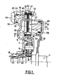
- a motor not shown drives the shaft 1 which is the input shaft of the device object of the invention.
- a shock absorber, not shown, can be interposed between the motor and this shaft.
- the shaft 1 rotates a sun gear 2.
- the latter meshes with satellites, preferably three in number 31, 32 and 33.
- the planet carrier is formed by two flanges 4 and 5.
- a crown 6 completes the planetary gear train. It is attached to the flange 7 which rotates the output shaft 8 of the device.
- the flange 4 of the planet carrier which can be made of stamped sheet metal is in the form of a double bell and carries a single disc 9 extending radially on either side of a outer wall 40. To this disc are attached two friction linings 10 and 11 respectively of the brake and the clutch.
- Each of these fittings 10 and 11 will advantageously be chosen double or two-sided.
- the double-sided brake lining 10 cooperates with a plate 12 and a counter plate 13 immobilized in rotation by suitable connections to the casing 14.
- a hydraulic cylinder constituted by an annular chamber 15 in this casing and an annular piston 16 completes the device, as well as seals, 24 and 25 and the ring 27 for stopping the counter-plate 13.
- the two-sided lining 11 of the clutch cooperates with a plate 17 and a counter plate 18 which are carried by a bell 19 secured to the shaft 1.
- This bell rotates the plates 17 and 18 in rotation. It can be made from stamped sheet metal and welded to the shaft 1. It also carries a hydraulic cylinder constituted by an annular chamber 20 and an annular piston 21. The device is completed by seals 28 and 29 and a stop ring 30.
- the flange 4 of the planet carrier makes it possible to position the planetary gear at the center of the disc 9, which makes it possible to reduce the axial size of the device.
- This flange 4 also includes an annular deformation 34 pierced with radial orifices 35, which act as an oil collector and allow the lubrication and cooling of the linings 10 and 11.
- the brake and clutch cylinders are located on either side of the plane of the disc 9.
- the disc 9 is centered by construction between the plates of the element not tightened (when the other is tightened). This allows a reduction in parasitic streaks.
- Spacing elements for example springs 41 and 42, can be incorporated into the device to ensure the spacing of the plates 12 and 13 on the one hand, 17 and 18 on the other hand, in the absence of control pressure in rooms 15 and 20.
- the positioning of the planet carrier is ensured by the rings 22 and possibly 23 placed respectively on the shaft 1 and in the shaft 8.
- a motor not shown drives the shaft 1 which is the input shaft of the device which is the subject of the invention.
- a shock absorber can be interposed between the motor and this shaft.
- the shaft 1 rotates a sun gear 2.
- the latter meshes with satellites, preferably three in number 31, 32 and 33.
- the planet carrier consists of two flanges 4 and 50.
- a crown 6 completes the train epicycloidal. It is attached to a bell 51 which rotates the output shaft 8 of the device.
- the flange 50 of the planet carrier which can be made of stamped sheet metal is bell-shaped, and carries a single disc 9 extending radially on either side of an outer wall 59.
- the two-sided brake lining 10 cooperates with a plate 94 and a counter-plate 95 immobilized in rotation by adequate connections to the casing 14.
- a hydraulic cylinder constituted by an annular chamber 93 in this casing and an annular piston 90 completes the device as well as seals 91 and 92.
- the stop ring 96 of the backing plate 95 and the spacer springs 97 complete the brake.
- the jack in the clutch is rotatably connected to the shaft 8.
- the motor in the absence of a control pressure in the clutch cylinder or in the brake cylinder, which in any case does not rotate, the motor can rotate the shaft 1 to high speeds without setting. in rotation of the shaft 8.
- the flange 50 of the planet carrier is simplified.
- the bell 51 can be obtained in aluminum casting, in which the crown 6 is fixed, and said bell 51 always drives the shaft 8.
- This bell 51 carries and rotates the plate 52 and the counter plate 53 of the clutch.
- This bell 51 also carries the annular piston 54.
- the seals 55, 56, the stop ring 57 and the spacer springs 58 complete the clutch.
- the brake and clutch cylinders are located on either side of the plane of the disc 9.
- the disc 9 is centered by construction between the plates of the element not tightened (when the other is tightened). This allows a reduction in parasitic streaks.
- the positioning of the planet carrier is ensured by rings 22 and possibly 23 placed respectively on the shaft 1 and in the shaft 8.
- the two friction linings of the brake and of the clutch are no longer carried by a single disc, but by two discs.
- the claimed advantage disappears but it is possible if necessary to position the two jacks on the same side of their respective discs.
- a motor not shown drives the shaft 1 which is the input shaft of the device object of the invention.
- a shock absorber not shown, can be interposed between the motor and this shaft.
- the shaft 1 rotates a sun gear 2.
- the latter meshes with satellites, preferably three in number 31, 32 and 33.
- the planet carrier is formed by two flanges 4 and 60.
- a crown 6 completes the planetary gear. It is attached to a bell 63 which rotates the output shaft 8 of the device.
- the flange 60 of the planet carrier which can be made of stamped sheet metal, is bell-shaped and carries a clutch disc 61 and a brake disc 62 extending radially on either side of an outer wall. 83.
- To these discs 61 and 62 are attached respectively two friction linings 84 and 85 respectively of the clutch and the brake.
- Each of these linings 84 and 85 will advantageously be chosen double or two-sided.
- the disc 62 of the brake is therefore dissociated from the disc 61 of the clutch.
- the two-sided brake lining 85 cooperates with a plate 78 and a counter plate 79 immobilized in rotation by suitable connections to the hub 72 secured to the casing of the device.
- the bell 63 contains the clutch cylinder, consisting of an annular piston 64 with seals 65 and 66, an annular chamber 67, plates 68 and counter plate 69, a stop ring 70 and springs spacing 71.
- a needle bearing 82 housed in the hub 72 makes it possible to center the shaft 1.
- the positioning of the planet carrier is ensured by rings 22 and possibly 23 placed respectively on the shaft 1 and in the shaft 8.
- the disc carrying the brake lining is positioned differently.
- the mean radius of this disc is reduced.
- the clutch cylinder is placed around the planetary gear.
Landscapes
- Engineering & Computer Science (AREA)
- General Engineering & Computer Science (AREA)
- Mechanical Engineering (AREA)
- Braking Arrangements (AREA)
- Structure Of Transmissions (AREA)
- Hybrid Electric Vehicles (AREA)
- Hydraulic Clutches, Magnetic Clutches, Fluid Clutches, And Fluid Joints (AREA)
Applications Claiming Priority (2)
| Application Number | Priority Date | Filing Date | Title |
|---|---|---|---|
| FR8307651 | 1983-05-06 | ||
| FR8307651A FR2545566B1 (fr) | 1983-05-06 | 1983-05-06 | Dispositif automatisable de demarrage en marche avant et en marche arriere |
Publications (1)
| Publication Number | Publication Date |
|---|---|
| EP0125977A1 true EP0125977A1 (de) | 1984-11-21 |
Family
ID=9288679
Family Applications (1)
| Application Number | Title | Priority Date | Filing Date |
|---|---|---|---|
| EP84400896A Withdrawn EP0125977A1 (de) | 1983-05-06 | 1984-05-03 | Automatisierbare Vorrichtung zum Vorwärts- und Rückwärtsanfahren |
Country Status (4)
| Country | Link |
|---|---|
| US (1) | US4610181A (de) |
| EP (1) | EP0125977A1 (de) |
| ES (1) | ES8502525A1 (de) |
| FR (1) | FR2545566B1 (de) |
Families Citing this family (9)
| Publication number | Priority date | Publication date | Assignee | Title |
|---|---|---|---|---|
| JPH0613395Y2 (ja) * | 1987-12-17 | 1994-04-06 | 三菱自動車工業株式会社 | 自動変速機のワンウェイクラッチ取付構造 |
| US5026334A (en) * | 1989-04-03 | 1991-06-25 | Deere & Company | Single piston activation of a planetary transmission |
| EP0995930B1 (de) * | 1998-10-22 | 2003-05-28 | Sheng-Tsai Tseng | Fahrzeuggetriebe |
| JP4800472B2 (ja) * | 2000-11-06 | 2011-10-26 | Nskワーナー株式会社 | 発進クラッチ及び発進クラッチの制御方法 |
| DE10345321A1 (de) * | 2003-09-30 | 2005-04-14 | Deere & Company, Moline | Kupplungs- und Bremseinheit |
| US7485066B2 (en) * | 2005-08-10 | 2009-02-03 | Luk Lamellen Und Kupplungsbau Beteiligungs Kg | Geared torque converter with multi-plate clutches and planetary gearset |
| WO2007076749A2 (de) * | 2005-12-22 | 2007-07-12 | Luk Lamellen Und Kupplungsbau Beteiligungs Kg | Kombiniertes drehmomentwandlungs- und übertragungssystem sowie verfahren dafür |
| JP2009534607A (ja) | 2006-04-26 | 2009-09-24 | ルーク ラメレン ウント クツプルングスバウ ベタイリグングス コマンディートゲゼルシャフト | 遊星歯車装置を備えたトルクコンバータ |
| DE102019208626B3 (de) * | 2019-06-13 | 2020-02-06 | Magna Pt B.V. & Co. Kg | Variable Kupplungsanordnung mit zwei konzentrisch angeordneten Kupplungen |
Citations (8)
| Publication number | Priority date | Publication date | Assignee | Title |
|---|---|---|---|---|
| US2174672A (en) * | 1936-11-16 | 1939-10-03 | Zahnradfabrik Friedrichshafen | Planet gear |
| US3131582A (en) * | 1961-02-20 | 1964-05-05 | Borg Warner | Transmission mechanism |
| FR1530227A (fr) * | 1967-07-04 | 1968-06-21 | Self Changing Gears Ltd | Mécanisme auxiliaire de surmultiplication de vitesse |
| DE1450784A1 (de) * | 1964-05-27 | 1970-01-29 | Anton Ottenschlaeger | Kupplung mit Wendetriebsatz |
| US3563114A (en) * | 1969-07-22 | 1971-02-16 | Ernest R Casale | Forward and reverse planetary gearing |
| US3728913A (en) * | 1970-06-02 | 1973-04-24 | Yanmar Diesel Engine Co | Planetary gear type reversing device |
| FR2325851A1 (fr) * | 1975-09-25 | 1977-04-22 | Renault | Tambour porte-disques rotatif poour embrayages ou freins multidisques |
| GB2115090A (en) * | 1982-02-16 | 1983-09-01 | Sperry Corp | Electric clutch-brake apparatus for operating planetary reversing gear |
Family Cites Families (9)
| Publication number | Priority date | Publication date | Assignee | Title |
|---|---|---|---|---|
| US2870655A (en) * | 1957-02-20 | 1959-01-27 | Allis Chalmers Mfg Co | Change speed transmission |
| US3020990A (en) * | 1958-07-07 | 1962-02-13 | Us Industries Inc | Transmissions |
| US3069929A (en) * | 1960-01-07 | 1962-12-25 | Eaton Mfg Co | Automotive device |
| FR2079531A5 (de) * | 1970-02-04 | 1971-11-12 | Peugeot & Renault | |
| FR2187064A5 (de) * | 1970-06-24 | 1974-01-11 | Peugeot & Renault | |
| US3685371A (en) * | 1971-04-05 | 1972-08-22 | James W Crooks | Reversing transmission |
| US4010833A (en) * | 1975-02-19 | 1977-03-08 | Zahnradfabrik Friedrichshafen Ag | Clutch assembly for planetary-gear trains |
| JPS5779332A (en) * | 1980-11-06 | 1982-05-18 | Nissan Motor Co Ltd | Clutch drum |
| JPS58654A (ja) * | 1981-06-23 | 1983-01-05 | Honda Motor Co Ltd | 車両用変速機 |
-
1983
- 1983-05-06 FR FR8307651A patent/FR2545566B1/fr not_active Expired
-
1984
- 1984-05-03 EP EP84400896A patent/EP0125977A1/de not_active Withdrawn
- 1984-05-04 ES ES532200A patent/ES8502525A1/es not_active Expired
- 1984-05-07 US US06/607,501 patent/US4610181A/en not_active Expired - Fee Related
Patent Citations (8)
| Publication number | Priority date | Publication date | Assignee | Title |
|---|---|---|---|---|
| US2174672A (en) * | 1936-11-16 | 1939-10-03 | Zahnradfabrik Friedrichshafen | Planet gear |
| US3131582A (en) * | 1961-02-20 | 1964-05-05 | Borg Warner | Transmission mechanism |
| DE1450784A1 (de) * | 1964-05-27 | 1970-01-29 | Anton Ottenschlaeger | Kupplung mit Wendetriebsatz |
| FR1530227A (fr) * | 1967-07-04 | 1968-06-21 | Self Changing Gears Ltd | Mécanisme auxiliaire de surmultiplication de vitesse |
| US3563114A (en) * | 1969-07-22 | 1971-02-16 | Ernest R Casale | Forward and reverse planetary gearing |
| US3728913A (en) * | 1970-06-02 | 1973-04-24 | Yanmar Diesel Engine Co | Planetary gear type reversing device |
| FR2325851A1 (fr) * | 1975-09-25 | 1977-04-22 | Renault | Tambour porte-disques rotatif poour embrayages ou freins multidisques |
| GB2115090A (en) * | 1982-02-16 | 1983-09-01 | Sperry Corp | Electric clutch-brake apparatus for operating planetary reversing gear |
Also Published As
| Publication number | Publication date |
|---|---|
| FR2545566A1 (fr) | 1984-11-09 |
| ES532200A0 (es) | 1985-01-01 |
| FR2545566B1 (fr) | 1989-06-02 |
| US4610181A (en) | 1986-09-09 |
| ES8502525A1 (es) | 1985-01-01 |
Similar Documents
| Publication | Publication Date | Title |
|---|---|---|
| BE834378A (fr) | Differentiel a glissement limite avec des moyens de commande d'embrayage | |
| EP0125977A1 (de) | Automatisierbare Vorrichtung zum Vorwärts- und Rückwärtsanfahren | |
| FR2767371A1 (fr) | Convertisseur de couple comportant un embrayage a verrouillage, et son procede de fabrication | |
| EP3825568B1 (de) | Vorrichtung zur drehmomentübertragung | |
| WO2015092216A1 (fr) | Ensemble de transmission equipe d'un amortisseur pendulaire s'etendant radialement a l'exterieur d'un dispositif d'embrayage | |
| EP0854284B1 (de) | Anlasser für Motorfahrzeug mit epizyklischen Untersetzungsgetriebe und Momentbegrenzer | |
| FR2657930A1 (fr) | Embrayage a deux disques. | |
| FR2675866A1 (fr) | Dispositif de transmission a viscocoupleur, notamment pour vehicules automobile. | |
| FR2600391A1 (fr) | Ensemble de transmission pour tracteur | |
| EP3237244B1 (de) | Hydraulikdrehmomentmotor | |
| EP0080947B1 (de) | Sperrvorrichtung für Differentialgetriebe | |
| FR3014986A1 (fr) | Systeme doubleur de gamme pour transmission automatique | |
| EP0139578A1 (de) | Riemengetriebe mit umkehrendem Drehmomentwandler | |
| FR2706010A1 (fr) | Boîte de vitesses à train épicycloïdal. | |
| EP0850795B1 (de) | Antriebsvorrichtung für ein Kraftfahrzeugrad mit einer besonderen Anordnung von Motor und Untersetzungsgetriebe | |
| EP3685070A1 (de) | Drehmomentübertragungsvorrichtung, torsionsdämpfer und zugehörige anordnung | |
| EP3111111B1 (de) | Epizyklisches zahnradgetriebe, insbesondere für ein kraftfahrzeuggetriebe | |
| EP3857090B1 (de) | Kompakter doppelnasskupplungsmechanismus | |
| FR3078376A1 (fr) | Dispositif de transmission pour vehicule hybride | |
| FR3033612A1 (fr) | Transmission compacte a double embrayage multidisque humide pour boite de vitesses d'un vehicule automobile | |
| FR3024510A1 (fr) | Dispositif d'embrayage pour un vehicule automobile | |
| FR3115081A1 (fr) | « dispositif de rappel elastique pour systeme d’embrayage » | |
| JPS59159448A (ja) | 自動変速機の動力伝達装置 | |
| FR3129189A1 (fr) | Embrayage humide amélioré pour système de groupe motopropulseur | |
| FR2829539A1 (fr) | Boite de vitesses automatique a deux embrayages en ligne |
Legal Events
| Date | Code | Title | Description |
|---|---|---|---|
| PUAI | Public reference made under article 153(3) epc to a published international application that has entered the european phase |
Free format text: ORIGINAL CODE: 0009012 |
|
| 17P | Request for examination filed |
Effective date: 19840507 |
|
| AK | Designated contracting states |
Designated state(s): BE DE GB IT NL SE |
|
| 17Q | First examination report despatched |
Effective date: 19860313 |
|
| STAA | Information on the status of an ep patent application or granted ep patent |
Free format text: STATUS: THE APPLICATION IS DEEMED TO BE WITHDRAWN |
|
| 18D | Application deemed to be withdrawn |
Effective date: 19860724 |
|
| RIN1 | Information on inventor provided before grant (corrected) |
Inventor name: BAUDOIN, PATRICE Inventor name: HOULEY, DANIEL |