EP0125977A1 - Automatable device to initiate forward and backward drive - Google Patents
Automatable device to initiate forward and backward drive Download PDFInfo
- Publication number
- EP0125977A1 EP0125977A1 EP84400896A EP84400896A EP0125977A1 EP 0125977 A1 EP0125977 A1 EP 0125977A1 EP 84400896 A EP84400896 A EP 84400896A EP 84400896 A EP84400896 A EP 84400896A EP 0125977 A1 EP0125977 A1 EP 0125977A1
- Authority
- EP
- European Patent Office
- Prior art keywords
- clutch
- brake
- disc
- starting device
- automated
- Prior art date
- Legal status (The legal status is an assumption and is not a legal conclusion. Google has not performed a legal analysis and makes no representation as to the accuracy of the status listed.)
- Withdrawn
Links
- 229910052751 metal Inorganic materials 0.000 claims description 9
- 239000002184 metal Substances 0.000 claims description 9
- 238000010276 construction Methods 0.000 claims description 6
- 238000002485 combustion reaction Methods 0.000 claims 1
- 230000021715 photosynthesis, light harvesting Effects 0.000 abstract 1
- 239000006096 absorbing agent Substances 0.000 description 3
- 230000035939 shock Effects 0.000 description 3
- 125000006850 spacer group Chemical group 0.000 description 3
- 230000005540 biological transmission Effects 0.000 description 2
- 230000003071 parasitic effect Effects 0.000 description 2
- 229910052782 aluminium Inorganic materials 0.000 description 1
- XAGFODPZIPBFFR-UHFFFAOYSA-N aluminium Chemical compound [Al] XAGFODPZIPBFFR-UHFFFAOYSA-N 0.000 description 1
- 238000005266 casting Methods 0.000 description 1
- 238000001816 cooling Methods 0.000 description 1
- 238000005265 energy consumption Methods 0.000 description 1
- 230000003100 immobilizing effect Effects 0.000 description 1
- 238000005461 lubrication Methods 0.000 description 1
Images


Classifications
-
- F—MECHANICAL ENGINEERING; LIGHTING; HEATING; WEAPONS; BLASTING
- F16—ENGINEERING ELEMENTS AND UNITS; GENERAL MEASURES FOR PRODUCING AND MAINTAINING EFFECTIVE FUNCTIONING OF MACHINES OR INSTALLATIONS; THERMAL INSULATION IN GENERAL
- F16H—GEARING
- F16H37/00—Combinations of mechanical gearings, not provided for in groups F16H1/00 - F16H35/00
- F16H37/02—Combinations of mechanical gearings, not provided for in groups F16H1/00 - F16H35/00 comprising essentially only toothed or friction gearings
- F16H37/04—Combinations of toothed gearings only
- F16H37/042—Combinations of toothed gearings only change gear transmissions in group arrangement
- F16H37/046—Combinations of toothed gearings only change gear transmissions in group arrangement with an additional planetary gear train, e.g. creep gear, overdrive
-
- F—MECHANICAL ENGINEERING; LIGHTING; HEATING; WEAPONS; BLASTING
- F16—ENGINEERING ELEMENTS AND UNITS; GENERAL MEASURES FOR PRODUCING AND MAINTAINING EFFECTIVE FUNCTIONING OF MACHINES OR INSTALLATIONS; THERMAL INSULATION IN GENERAL
- F16H—GEARING
- F16H3/00—Toothed gearings for conveying rotary motion with variable gear ratio or for reversing rotary motion
- F16H3/44—Toothed gearings for conveying rotary motion with variable gear ratio or for reversing rotary motion using gears having orbital motion
- F16H3/46—Gearings having only two central gears, connected by orbital gears
- F16H3/60—Gearings for reversal only
Definitions
- the present invention relates to an automatable device for starting forward and reverse.
- the object of the present invention is to provide an automated device for starting in forward and in reverse, in particular for a motor vehicle with thermal engine, associating a simple planetary gear train with three satellites, a clutch and a brake, in order to give dissipations. reduced energy when starting in reverse.
- the invention relates to an automatable device which comprises on the one hand a simple planetary gear, and on the other hand a brake and a clutch both consisting of a single disc with two friction linings , said clutch and brake being integral in rotation with one of the flanges of the planet carrier.
- the device according to the invention further comprises springs which are interposed between the plates and counter-plates of the clutch and of the brake.
- the flange of the planet carrier which carries the disks of the clutch and of the brake, is a bell made of stamped and cut sheet metal, which by notches located on its periphery ensures a connection in rotation with said discs.
- the clutch cylinder is integral in rotation with the input shaft.
- the clutch disc and the brake disc form a single disc.
- the bell which carries the single disc, comprises an annular deformation acting as an oil collector during rotation, which cooperates with radial orifices bringing the oil to the friction linings carried by said disc.
- the clutch and brake cylinders are located on either side of the plane of the disc carrying the friction linings, in a direction opposite to the axial direction, in such a way that the counter-plates of the brake pistons and of the clutch are positioned axially by construction, to center the disc in the middle of the plates of the element not tightened.
- the clutch cylinder is integral in rotation with the output shaft.
- the flange of the planet carrier which carries the disks of the clutch and of the brake is a bell made of stamped and cut sheet metal, which by notches located on its periphery, ensures a connection in rotation with said disks.
- the clutch discs and the brake disc form a single disc.
- the clutch and brake cylinders are located in an opposite direction to the axial direction, so that the counter plates of the brake and the clutch are positioned axially by construction, to center the disc in the middle of the plates of the element not tightened.
- the clutch cylinder is integral in rotation with the output shaft.
- the flange of the planet carrier which carries the disks of the clutch and of the brake, is a bell made of stamped and cut sheet metal which by notches located on its periphery ensures a connection in rotation with said disks.
- the brake disc is dissociated from the clutch disc and located inside the bell.
- the brake plates are carried by a hub that is an integral part of the housing, said hub comprising a needle bearing carrying the input shaft.
- the clutch cylinder is integral in rotation with the output shaft.
- the brake disc is dissociated from the clutch disc.
- the flange of the planet carrier, which carries the disks of the clutch and of the brake, is a bell made of stamped and cut sheet metal which by notches located on its periphery ensures a connection in rotation with said disks.
- the clutch and brake cylinders are located on the same side of the disc planes in the same direction relative to the axial direction.
- Such a device according to the invention has the following advantages.
- Forward travel is obtained by joining any two of the three elements of the train by a clutch, for example the planet carrier and the sun gear or the planet carrier and the crown.
- a clutch for example the planet carrier and the sun gear or the planet carrier and the crown.
- the transmission ratio of the device defined as being the ratio between output speed and input speed is then + 1.
- Reverse gear is obtained by immobilizing the planet carrier relative to the housing, by means of a brake.
- the transmission ratio is then commonly between -0.4 and -0.8.
- the surfaces of the friction linings being most often determined by the energies to be dissipated, the specific energy being given, we understand the undersizing of the brake lining (s) which results from the use of a simple train with three satellites.
- a device according to the invention is thus obtained which is compact with a low drag and a reduced cost price.
- a motor not shown drives the shaft 1 which is the input shaft of the device object of the invention.
- a shock absorber, not shown, can be interposed between the motor and this shaft.
- the shaft 1 rotates a sun gear 2.
- the latter meshes with satellites, preferably three in number 31, 32 and 33.
- the planet carrier is formed by two flanges 4 and 5.
- a crown 6 completes the planetary gear train. It is attached to the flange 7 which rotates the output shaft 8 of the device.
- the flange 4 of the planet carrier which can be made of stamped sheet metal is in the form of a double bell and carries a single disc 9 extending radially on either side of a outer wall 40. To this disc are attached two friction linings 10 and 11 respectively of the brake and the clutch.
- Each of these fittings 10 and 11 will advantageously be chosen double or two-sided.
- the double-sided brake lining 10 cooperates with a plate 12 and a counter plate 13 immobilized in rotation by suitable connections to the casing 14.
- a hydraulic cylinder constituted by an annular chamber 15 in this casing and an annular piston 16 completes the device, as well as seals, 24 and 25 and the ring 27 for stopping the counter-plate 13.
- the two-sided lining 11 of the clutch cooperates with a plate 17 and a counter plate 18 which are carried by a bell 19 secured to the shaft 1.
- This bell rotates the plates 17 and 18 in rotation. It can be made from stamped sheet metal and welded to the shaft 1. It also carries a hydraulic cylinder constituted by an annular chamber 20 and an annular piston 21. The device is completed by seals 28 and 29 and a stop ring 30.
- the flange 4 of the planet carrier makes it possible to position the planetary gear at the center of the disc 9, which makes it possible to reduce the axial size of the device.
- This flange 4 also includes an annular deformation 34 pierced with radial orifices 35, which act as an oil collector and allow the lubrication and cooling of the linings 10 and 11.
- the brake and clutch cylinders are located on either side of the plane of the disc 9.
- the disc 9 is centered by construction between the plates of the element not tightened (when the other is tightened). This allows a reduction in parasitic streaks.
- Spacing elements for example springs 41 and 42, can be incorporated into the device to ensure the spacing of the plates 12 and 13 on the one hand, 17 and 18 on the other hand, in the absence of control pressure in rooms 15 and 20.
- the positioning of the planet carrier is ensured by the rings 22 and possibly 23 placed respectively on the shaft 1 and in the shaft 8.
- a motor not shown drives the shaft 1 which is the input shaft of the device which is the subject of the invention.
- a shock absorber can be interposed between the motor and this shaft.
- the shaft 1 rotates a sun gear 2.
- the latter meshes with satellites, preferably three in number 31, 32 and 33.
- the planet carrier consists of two flanges 4 and 50.
- a crown 6 completes the train epicycloidal. It is attached to a bell 51 which rotates the output shaft 8 of the device.
- the flange 50 of the planet carrier which can be made of stamped sheet metal is bell-shaped, and carries a single disc 9 extending radially on either side of an outer wall 59.
- the two-sided brake lining 10 cooperates with a plate 94 and a counter-plate 95 immobilized in rotation by adequate connections to the casing 14.
- a hydraulic cylinder constituted by an annular chamber 93 in this casing and an annular piston 90 completes the device as well as seals 91 and 92.
- the stop ring 96 of the backing plate 95 and the spacer springs 97 complete the brake.
- the jack in the clutch is rotatably connected to the shaft 8.
- the motor in the absence of a control pressure in the clutch cylinder or in the brake cylinder, which in any case does not rotate, the motor can rotate the shaft 1 to high speeds without setting. in rotation of the shaft 8.
- the flange 50 of the planet carrier is simplified.
- the bell 51 can be obtained in aluminum casting, in which the crown 6 is fixed, and said bell 51 always drives the shaft 8.
- This bell 51 carries and rotates the plate 52 and the counter plate 53 of the clutch.
- This bell 51 also carries the annular piston 54.
- the seals 55, 56, the stop ring 57 and the spacer springs 58 complete the clutch.
- the brake and clutch cylinders are located on either side of the plane of the disc 9.
- the disc 9 is centered by construction between the plates of the element not tightened (when the other is tightened). This allows a reduction in parasitic streaks.
- the positioning of the planet carrier is ensured by rings 22 and possibly 23 placed respectively on the shaft 1 and in the shaft 8.
- the two friction linings of the brake and of the clutch are no longer carried by a single disc, but by two discs.
- the claimed advantage disappears but it is possible if necessary to position the two jacks on the same side of their respective discs.
- a motor not shown drives the shaft 1 which is the input shaft of the device object of the invention.
- a shock absorber not shown, can be interposed between the motor and this shaft.
- the shaft 1 rotates a sun gear 2.
- the latter meshes with satellites, preferably three in number 31, 32 and 33.
- the planet carrier is formed by two flanges 4 and 60.
- a crown 6 completes the planetary gear. It is attached to a bell 63 which rotates the output shaft 8 of the device.
- the flange 60 of the planet carrier which can be made of stamped sheet metal, is bell-shaped and carries a clutch disc 61 and a brake disc 62 extending radially on either side of an outer wall. 83.
- To these discs 61 and 62 are attached respectively two friction linings 84 and 85 respectively of the clutch and the brake.
- Each of these linings 84 and 85 will advantageously be chosen double or two-sided.
- the disc 62 of the brake is therefore dissociated from the disc 61 of the clutch.
- the two-sided brake lining 85 cooperates with a plate 78 and a counter plate 79 immobilized in rotation by suitable connections to the hub 72 secured to the casing of the device.
- the bell 63 contains the clutch cylinder, consisting of an annular piston 64 with seals 65 and 66, an annular chamber 67, plates 68 and counter plate 69, a stop ring 70 and springs spacing 71.
- a needle bearing 82 housed in the hub 72 makes it possible to center the shaft 1.
- the positioning of the planet carrier is ensured by rings 22 and possibly 23 placed respectively on the shaft 1 and in the shaft 8.
- the disc carrying the brake lining is positioned differently.
- the mean radius of this disc is reduced.
- the clutch cylinder is placed around the planetary gear.
Abstract
Dispositif automatisable de démarrage en marche avant et en marche arrière, notamment pour véhicule automobile à moteur thermique, caractérisé en ce qu'il comporte un train épicycloîdal simple à trois satellites associé à un embrayage et à un frein afin de donner des dissipations d'énergie réduites lors des démarrages en marche arrière.Automable device for starting forward and reverse, in particular for a motor vehicle with a thermal engine, characterized in that it comprises a simple planetary gear train with three satellites associated with a clutch and a brake in order to give energy dissipation reduced when starting in reverse.
Description
La présente invention se rapporte à un dispositif automatisable de démarrage en marche avant et en marche arrière.The present invention relates to an automatable device for starting forward and reverse.
De nombreux dispositifs de démarrage en marche avant et en marche arrière existent pour les véhicules automobiles à moteur thermique, parmi lesquels on peut citer :
- - d'une part, les embrayages secs ou humides, monodisqueoumulti- disques, à commande manuelle ou automatique, celle-ci pouvant être par exemple du type centrifuge à masselottes, les coupleurs les convertisseurs, en association avec des dispositifs inverseurs ;
- - d'autre part, les associations train épicycloidal à six satellites - embrayage - frein.
- - on the one hand, dry or wet clutches, single-disc or multi-disc, with manual or automatic control, this can for example be of the centrifugal type with counterweights, the couplers the converters, in association with reversing devices;
- - on the other hand, the planetary gear train with six satellites - clutch - brake.
Tous ces dispositifs présentent des inconvénients soit en prix de revient, soit en consommation d'énergie, soit en encombrement et en poids, soit en agrément d'utilisation.All these devices have drawbacks either in cost price, or in energy consumption, or in size and weight, or in convenience of use.
Le but de la présente invention est de réaliser un dispositif automatisable de démarrage en marche avant et en marche arrière, notamment pour véhicule automobile à moteur thermique, associant un train épicycloidal simple à trois satellites, un embrayage et un frein, afin de donner des dissipations d'énergie réduites lors des démarrages en marche arrière.The object of the present invention is to provide an automated device for starting in forward and in reverse, in particular for a motor vehicle with thermal engine, associating a simple planetary gear train with three satellites, a clutch and a brake, in order to give dissipations. reduced energy when starting in reverse.
A cet effet l'invention a pour objet un dispositif automatisable qui comporte d'une part un train épicycloidal simple, et d'autre part un frein et un embrayage consistant l'un et l'autre en un seul disque avec deux garnitures de friction, lesdits embrayage et frein étant solidaires en rotation de l'un des flasques du porte-satellites. Le dispositif selon l'invention comporte de plus des ressorts qui sont interposés entre les plateaux et contre-plateaux de l'embrayage et du frein.To this end the invention relates to an automatable device which comprises on the one hand a simple planetary gear, and on the other hand a brake and a clutch both consisting of a single disc with two friction linings , said clutch and brake being integral in rotation with one of the flanges of the planet carrier. The device according to the invention further comprises springs which are interposed between the plates and counter-plates of the clutch and of the brake.
Selon un mode de réalisation de l'invention, le flasque du porte-satellites, qui porte les disques de l'embrayage et du frein, est une cloche en tôle emboutie et découpée, qui par des encoches situées sur sa périphérie assure une liaison en rotation avec lesdits disques. Le vérin de 1' embrayage est solidaire en rotation de l'arbre d'entrée. Le disque de l'embrayage et le disque du frein font un seul et même disque.According to one embodiment of the invention, the flange of the planet carrier, which carries the disks of the clutch and of the brake, is a bell made of stamped and cut sheet metal, which by notches located on its periphery ensures a connection in rotation with said discs. The clutch cylinder is integral in rotation with the input shaft. The clutch disc and the brake disc form a single disc.
La cloche, qui porte le disque unique, comporte un déformé annulaire faisant office de collecteur d'huile lors de la rotation, qui coopère avec des orifices radiaux amenant l'huile vers les garnitures de friction portée par ledit disque.The bell, which carries the single disc, comprises an annular deformation acting as an oil collector during rotation, which cooperates with radial orifices bringing the oil to the friction linings carried by said disc.
Les vérins de l'embrayage et du frein sont situés de part et d'autre du plan du disque portant les garnitures de friction, dans un sens opposé par rapport à la direction axiale, de telle manière que les contre-plateaux des pistons du frein et de l'embrayage soient positionnés axialement par construction, pour centrer le disque au milieu des plateaux de l'élément non serré.The clutch and brake cylinders are located on either side of the plane of the disc carrying the friction linings, in a direction opposite to the axial direction, in such a way that the counter-plates of the brake pistons and of the clutch are positioned axially by construction, to center the disc in the middle of the plates of the element not tightened.
Selon un mode de réalisation de l'invention, le vérin de l'embrayage est solidaire en rotation de l'arbre de sortie. Le flasque du porte-satellites qui porte les disques de l'embrayage et du frein est une cloche en tôle emboutie et découpée, qui par des encoches situées sur sa périphérie, assure une liaison en rotation avec lesdits disques.According to one embodiment of the invention, the clutch cylinder is integral in rotation with the output shaft. The flange of the planet carrier which carries the disks of the clutch and of the brake is a bell made of stamped and cut sheet metal, which by notches located on its periphery, ensures a connection in rotation with said disks.
Les disques de l'embrayage et le disque du frein font un seul et même disque. Les vérins de l'embrayage et du frein sont situés dans un sens opposé par rapport à la direction axiale, de telle manière que les contre-plateaux des pistons du frein et de l'embrayage soient positionnés axialement par construction, pour centrer le disque au milieu des plateaux de l'élément non serré.The clutch discs and the brake disc form a single disc. The clutch and brake cylinders are located in an opposite direction to the axial direction, so that the counter plates of the brake and the clutch are positioned axially by construction, to center the disc in the middle of the plates of the element not tightened.
Selon un mode de réalisation de l'invention, le vérin de l'embrayage est solidaire en rotation de l'arbre de sortie. Le flasque du porte-satellites, qui porte les disques de l'embrayage et du frein, est une cloche en tôle emboutie et découpée qui par des encoches situées sur sa périphérie assure une liaison en rotation avec lesdits disques.According to one embodiment of the invention, the clutch cylinder is integral in rotation with the output shaft. The flange of the planet carrier, which carries the disks of the clutch and of the brake, is a bell made of stamped and cut sheet metal which by notches located on its periphery ensures a connection in rotation with said disks.
Le disque du frein est dissocié du disque de l'embrayage et situé à l'intérieur de la cloche. Les plateaux du frein sont portés par un moyeu faisant partie intégrante du carter, ledit moyeu comportant un roulement à aiguilles portant l'arbre d'entrée.The brake disc is dissociated from the clutch disc and located inside the bell. The brake plates are carried by a hub that is an integral part of the housing, said hub comprising a needle bearing carrying the input shaft.
Selon un mode de réalisation de l'invention, le vérin de l'embrayage est solidaire en rotation de l'arbre de sortie. Le disque du frein est dissocié du disque de l'embrayage. Le flasque du porte-satellites, qui porte les disques de l'embrayage et du frein, est une cloche en tôle emboutie et découpée qui par des encoches situées sur sa périphérie assure une liaison en rotation avec lesdits disques. Les vérins de l'embrayage et du frein sont situés du même côté des plans des disques dans le même sens par rapport à la direction axiale.According to one embodiment of the invention, the clutch cylinder is integral in rotation with the output shaft. The brake disc is dissociated from the clutch disc. The flange of the planet carrier, which carries the disks of the clutch and of the brake, is a bell made of stamped and cut sheet metal which by notches located on its periphery ensures a connection in rotation with said disks. The clutch and brake cylinders are located on the same side of the disc planes in the same direction relative to the axial direction.
Un tel dispositif suivant l'invention présente les avantages ci-après.Such a device according to the invention has the following advantages.
- Le mouvement entre par le planétaire du train épicycloidal et sort par sa couronne.- The movement enters through the planetary of the planetary gear and exits through its crown.
La marche avant est obtenue en solidarisant par un embrayage deux quelconques des trois éléments du train, par exemple le porte-satellites et le planétaire ou le porte-satellites et la couronne.Forward travel is obtained by joining any two of the three elements of the train by a clutch, for example the planet carrier and the sun gear or the planet carrier and the crown.
Le rapport de transmission du dispositif, défini comme étant le rapport vitesse de sortie sur vitesse d'entrée vaut alors + 1.The transmission ratio of the device, defined as being the ratio between output speed and input speed is then + 1.
La marche arrière est obtenue en immobilisant le porte-satellites par rapport au carter, par l'intermédiaire d'un frein. Le rapport de transmission est alors communément compris entre - 0,4 et -0,8.Reverse gear is obtained by immobilizing the planet carrier relative to the housing, by means of a brake. The transmission ratio is then commonly between -0.4 and -0.8.
Des conditions de démarrage étant imposées, les énergies dissipées dans le cas d'un démarrage en marche arrière seront de ce fait beaucoup plus faibles que dans le cas d'un démarrage en marche avant.Starting conditions being imposed, the energies dissipated in the case of a reverse start will therefore be much lower than in the case of a forward start.
Même si le couple moteur est limité, de sorte que le couple aux roues soit le même que celui qu'on obtiendrait en marche avant, dans le cas d'un démarrage en marche arrière, l'énergie dissipée ne sera respectivement et pour les valeurs externes précédentes, que 16 et 64% de celle dissipée en marche avant.Even if the engine torque is limited, so that the torque at the wheels is the same as that which would be obtained in forward, in the case of a start in reverse, the dissipated energy will be respectively and for the values external sources, only 16 and 64% of that dissipated in forward.
Les surfaces des garnitures de friction étant le plus souvent déterminées par les énergies à dissiper, l'énergie spécifique étant donnée, on comprend le sous-dimensionnement de la ou des garnitures du frein qui résulte de l'utilisation d'un train simple à trois satellites.The surfaces of the friction linings being most often determined by the energies to be dissipated, the specific energy being given, we understand the undersizing of the brake lining (s) which results from the use of a simple train with three satellites.
On obtient ainsi un dispositif selon l'invention qui est compacte avec une traînée faible et un prix de revient réduit.A device according to the invention is thus obtained which is compact with a low drag and a reduced cost price.
D'autres caractéristiques et avantages de la présente invention ressortiront de la description qui suit de modes de réalisation donnés à titre d'exemple, en référence aux dessins annexés sur lesquels :
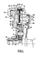
- - la figure 1 représente en coupe longitudinale une demi-vue du dispositif de l'invention selon un premier mode de réalisation;
- - la figure 2 représente en coupe longitudinale une demi-vue du dispositif de l'invention selon un second mode de réalisation ;
- - la figure 3 représente en coupe longitudinale une demi-vue du dispositif de l'invention selon un quatrième mode de réalisation.
- - Figure 1 shows in longitudinal section a half view of the device of the invention according to a first embodiment;
- - Figure 2 shows in longitudinal section a half view of the device of the invention according to a second embodiment;
- - Figure 3 shows in longitudinal section a half view of the device of the invention according to a fourth embodiment.
Dans un premier mode de réalisation de l'invention représenté sur la figure 1, un moteur non représenté entraîne l'arbre 1 qui est l'arbre d'entrée du dispositif objet de l'invention. Un amortisseur non représenté peut être interposé entre le moteur et cet arbre. L'arbre 1 entraîne en rotation un planétaire 2. Celui-ci engrène avec des satellites, préférentiellement au nombre de trois repères 31, 32 et 33. Le porte-satellites est constitué par deux flasques 4 et 5.In a first embodiment of the invention shown in Figure 1, a motor not shown drives the
Une couronne 6 complète le train épicycloldal. Elle est attachée au flasque 7 qui entraîne en rotation l'arbre 8 de sortie du dispositif. Dans ce premier mode de réalisation de l'invention, le flasque 4 du porte-satellites qui peut être réalisé en tôle emboutie est en forme de double cloche et porte un disque unique 9 s'étendant radialement de part et d'autre d'une paroi extérieure 40. A ce disque sont attachées deux garnitures de friction 10 et 11 respectivement du frein et de l'embrayage.A
Chacune de ces garnitures 10 et 11 sera avantageusement choisie double ou biface.Each of these
La garniture 10 biface du frein coopère avec un plateau 12 et un contre-plateau 13 immobilisés en rotation par des liaisons adéquates au carter 14.The double-
Un vérin hydraulique constitué par une chambre annulaire 15 dans ce carter et un piston annulaire 16 complète le dispositif, ainsi que des joints,24 et 25 et l'anneau 27 d'arrêt du contre-plateau 13.A hydraulic cylinder constituted by an
La garniture 11 biface de l'embrayage coopère avec un plateau 17 et un contre-plateau 18 qui sont portés par une cloche 19 solidaire de l'arbre 1.The two-
Cette cloche assure l'entraînement en rotation des plateaux 17 et 18. Elle peut être réalisée en tôle emboutie et soudée sur l'arbre 1. Elle porte aussi un vérin hydraulique constitué par une chambre annulaire 20 et un piston annulaire 21. Le dispositif est complété par les joints 28 et 29 et un anneau d'arrêt 30.This bell rotates the
De par sa forme, le flasque 4 du porte-satellites permet de positionner le train épicycloidal au centre du disque 9, ce qui permet de réduire l'encombrement axial du dispositif. Ce flasque 4 comporte aussi un déforme annulaire 34 percé d'orifices radiaux 35, qui jouent le rôle de collecteur d'huile et permettent la lubrification et le refroidissement des garnitures 10 et 11.By its shape, the
Les vérins du frein et de l'embrayage sont situés de part et d'autre du plan du disque 9. Ainsi, et dans la mesure où les contre-plateaux 13 et 18 sont judicieusement positionnés axialement, le disque 9 se trouve centré par construction entre les plateaux de l'élément non serré (lorsque l'autre est serré). Ceci permet une réduction des traînées parasites.The brake and clutch cylinders are located on either side of the plane of the
Des éléments d'écartement, par exemple des ressorts 41 et 42, peuvent être incorporés au dispositif pour assurer l'écartement des plateaux 12 et 13 d'une part, 17 et 18 d'autre part, en l'absence de pression de commande dans les chambres 15 et 20.Spacing elements, for example springs 41 and 42, can be incorporated into the device to ensure the spacing of the
Le positionnement du porte-satellites est assuré par les bagues 22 et éventuellement 23 placées respectivement sur l'arbre 1 et dans l'arbre 8.The positioning of the planet carrier is ensured by the
Dans un deuxième mode de réalisation de l'invention représenté sur la figure 2, un moteur non représenté entraîne l'arbre 1 qui est l'arbre d'entrée du dispositif objet de l'invention. Un amortisseur non représenté peut être interposé entre le moteur et cet arbre. L'arbre 1 entraine en rotation un planétaire 2. Celui-ci engrène avec des satellites, préférentiellement au nombre de trois repères 31, 32 et 33. Le porte-satellites est constitué par deux flasques 4 et 50. Une couronne 6 complète le train épicycloidal. Elle est attachée à une cloche 51 qui entraîne en rotation l'arbre 8 de sortie du dispositif.In a second embodiment of the invention shown in Figure 2, a motor not shown drives the
Le flasque 50 du porte-satellites qui peut être réalisé en tôle emboutie est en forme de cloche, et porte un disque unique 9 s'étendant radialement de part et d'autre d'une paroi extérieure 59.The
A ce disque sont attachées deux garnitures de friction 10 et 11 respectivement du frein et de l'embrayage. Chacune de ces garnitures 10 et 11 sera avantageusement choisie double ou biface. La garniture 10 biface du frein coopère avec un plateau 94 et un contre-plateau 95 immobilisés en rotation par des liaisons adéquates au carter 14. Un vérin hydraulique constitué par une chambre annulaire 93 dans ce carter et un piston annulaire 90 complète le dispositif ainsi que des joints 91 et 92. L'anneau 96 d'arrêt du contre-plateau 95 et les ressorts d'écartement 97 complètent le frein.To this disc are attached two
Dans ce deuxième mode de réalisation de l'invention (dessin n° 2), le vérin ds l'embrayage est solidaire en rotation de l'arbre 8.In this second embodiment of the invention (drawing No. 2), the jack in the clutch is rotatably connected to the
Il en résulte que, en l'absence d'une pression de commande dans le vérin de l'embrayage ou dans le vérin du frein, qui lui, de toutes façons, ne tourne pas, le moteur peut faire tourner l'arbre 1 à des vitesses élevées sans qu'il y ait mise. en rotation de l'arbre 8.As a result, in the absence of a control pressure in the clutch cylinder or in the brake cylinder, which in any case does not rotate, the motor can rotate the
Dans le premier mode de réalisation, ce n'était pas le cas : une pression dynamique centrifuge pouvait apparaître dans le vérin d'embrayage en l'absence de cette pression de commande.In the first embodiment, this was not the case: a dynamic centrifugal pressure could appear in the clutch cylinder in the absence of this control pressure.
Dans ce deuxième mode de réalisation, le flasque 50 du porte-satellites est simplifié. Par contre, la cloche 51 peut être obtenue en fonderie d'aluminium, dans laquelle est fixée la couronne 6, et ladite cloche 51 entraîne toujours l'arbre 8. Cette cloche 51 porte et entraîne en rotation le plateau 52 et le contre-plateau 53 de l'embrayage. Cette cloche 51 porte aussi le piston annulaire 54.In this second embodiment, the
Les joints 55, 56, l'anneau d'arrêt 57 et les ressorts d'écartement 58 complètent l'embrayage.The
Les vérins du frein et de l'embrayage sont situés de part et d'autre du plan du disque 9. Ainsi, et dans la mesure où les contre-plateaux 53 et 95 sont judicieusement positionnés axialement, le disque 9 se trouve centré par construction entre les plateaux de l'élément non serré (lorsque l'autre est serré). Ceci permet une réduction des traînées parasites.The brake and clutch cylinders are located on either side of the plane of the
Le positionnement du porte-satellites est assuré par des bagues 22 et éventuellement 23 placées respectivement sur l'arbre 1 et dans l'arbre 8.The positioning of the planet carrier is ensured by
Dans un troisième mode de réalisation de l'invention, les deux garnitures de friction du frein et de l'embrayage ne sont plus portés par un disque unique, mais par deux disques. L'avantage revendiqué disparaît mais on peut si nécessaire positionner les deux vérins du même côté de leurs disques respectifs.In a third embodiment of the invention, the two friction linings of the brake and of the clutch are no longer carried by a single disc, but by two discs. The claimed advantage disappears but it is possible if necessary to position the two jacks on the same side of their respective discs.
Dans un quatrième mode de réalisation de l'invention représenté sur la figure 3, un moteur non représenté entraîne l'arbre 1 qui est l'arbre d'entrée du dispositif objet de l'invention.In a fourth embodiment of the invention shown in Figure 3, a motor not shown drives the
Un amortisseur non représenté peut être interposé entre le moteur et cet arbre.A shock absorber, not shown, can be interposed between the motor and this shaft.
L'arbre 1 entraîne en rotation un planétaire 2. Celui-ci engrène avec des satellites, préférentiellement au nombre de trois repères 31, 32 et 33. Le porte-satellites est constitué par deux flasques 4 et 60.The
Une couronne 6 complète le train épicycloidal. Elle est attachée à une cloche 63 qui entraîne en rotation l'arbre 8 de sortie du dispositif.A
Le flasque 60 du porte-satellites, qui peut être réalisé en tôle emboutie, est en forme de cloche et porte un disque 61 d'embrayage et un disque 62 de frein s'étendant radialement de part et d'autre d'une paroi extérieure 83. A ces disques 61 et 62 sont attachées respectivement deux garnitures de friction 84 et 85 respectivement de l'embrayage et du frein. Chacune de ces garnitures 84 et 85 sera avantageusement choisie double ou biface. Le disque 62 du frein est donc dissocié du disque 61 de l'embrayage. La garniture 85 biface du frein coopère avec un plateau 78 et un contre-plateau 79 immobilisés en rotation par des liaisons adéquates au moyeu 72 solidaire du carter du dispositif.The
Un vérin hydraulique constitué par une chambre annulaire 77 dans ce carter et un piston annulaire 74 complète le dispositif ainsi que des joints 75 et 76. L'anneau 80 d'arrêt du contre-plateau 79 et les ressorts d'écartement 81 complètent le frein.A hydraulic cylinder constituted by an
La cloche 63 contient le vérin de l'embrayage, constitué par un piston annulaire 64 avec des joints d'étanchéité 65 et 66, une chambre annulaire 67, des plateau 68 et contre-plateau 69, un anneau d'arrêt 70 et des ressorts d'écartement 71.The
Un roulement à aiguilles 82 logé dans le moyeu 72 permet de centrer l'arbre 1. Le positionnement du porte-satellites est assuré par des bagues 22 et éventuellement 23 placées respectivement sur l'arbre 1 et dans l'arbre 8.A
Dans un quatrième mode de réalisation de l'invention , le disque portant la garniture du frein est positionné différemment. De manière à réduire la traînée du frein lorsqu'il n'est pas serré, ce qui est le cas sur un véhicule qui roule en marche avant, le rayon moyen de ce disque est réduit.In a fourth embodiment of the invention, the disc carrying the brake lining is positioned differently. In order to reduce the drag of the brake when it is not applied, which is the case on a vehicle traveling in forward gear, the mean radius of this disc is reduced.
En vu de réduire le plus possible les encombrements axial et diamétral du dispositif, le vérin de l'embrayage est placé autour du train épicycloidal.In order to minimize the axial and diametral dimensions of the device, the clutch cylinder is placed around the planetary gear.
Claims (17)
Applications Claiming Priority (2)
| Application Number | Priority Date | Filing Date | Title |
|---|---|---|---|
| FR8307651 | 1983-05-06 | ||
| FR8307651A FR2545566B1 (en) | 1983-05-06 | 1983-05-06 | AUTOMATED FORWARD AND REVERSE STARTING DEVICE |
Publications (1)
| Publication Number | Publication Date |
|---|---|
| EP0125977A1 true EP0125977A1 (en) | 1984-11-21 |
Family
ID=9288679
Family Applications (1)
| Application Number | Title | Priority Date | Filing Date |
|---|---|---|---|
| EP84400896A Withdrawn EP0125977A1 (en) | 1983-05-06 | 1984-05-03 | Automatable device to initiate forward and backward drive |
Country Status (4)
| Country | Link |
|---|---|
| US (1) | US4610181A (en) |
| EP (1) | EP0125977A1 (en) |
| ES (1) | ES532200A0 (en) |
| FR (1) | FR2545566B1 (en) |
Families Citing this family (9)
| Publication number | Priority date | Publication date | Assignee | Title |
|---|---|---|---|---|
| JPH0613395Y2 (en) * | 1987-12-17 | 1994-04-06 | 三菱自動車工業株式会社 | One-way clutch mounting structure for automatic transmission |
| US5026334A (en) * | 1989-04-03 | 1991-06-25 | Deere & Company | Single piston activation of a planetary transmission |
| EP0995930B1 (en) * | 1998-10-22 | 2003-05-28 | Sheng-Tsai Tseng | Automobile transmission device |
| JP4800472B2 (en) * | 2000-11-06 | 2011-10-26 | Nskワーナー株式会社 | Start clutch and start clutch control method |
| DE10345321A1 (en) * | 2003-09-30 | 2005-04-14 | Deere & Company, Moline | Clutch and brake unit |
| US7485066B2 (en) * | 2005-08-10 | 2009-02-03 | Luk Lamellen Und Kupplungsbau Beteiligungs Kg | Geared torque converter with multi-plate clutches and planetary gearset |
| JP5448454B2 (en) * | 2005-12-22 | 2014-03-19 | シェフラー テクノロジーズ アクチエンゲゼルシャフト ウント コンパニー コマンディートゲゼルシャフト | Combined torque conversion and torque transmission system alignment method therefor |
| DE112007000839A5 (en) | 2006-04-26 | 2009-01-15 | Luk Lamellen Und Kupplungsbau Beteiligungs Kg | Torque converter with planetary gear |
| DE102019208626B3 (en) * | 2019-06-13 | 2020-02-06 | Magna Pt B.V. & Co. Kg | Variable coupling arrangement with two concentrically arranged couplings |
Citations (8)
| Publication number | Priority date | Publication date | Assignee | Title |
|---|---|---|---|---|
| US2174672A (en) * | 1936-11-16 | 1939-10-03 | Zahnradfabrik Friedrichshafen | Planet gear |
| US3131582A (en) * | 1961-02-20 | 1964-05-05 | Borg Warner | Transmission mechanism |
| FR1530227A (en) * | 1967-07-04 | 1968-06-21 | Self Changing Gears Ltd | Auxiliary gear overdrive mechanism |
| DE1450784A1 (en) * | 1964-05-27 | 1970-01-29 | Anton Ottenschlaeger | Coupling with reversing gear set |
| US3563114A (en) * | 1969-07-22 | 1971-02-16 | Ernest R Casale | Forward and reverse planetary gearing |
| US3728913A (en) * | 1970-06-02 | 1973-04-24 | Yanmar Diesel Engine Co | Planetary gear type reversing device |
| FR2325851A1 (en) * | 1975-09-25 | 1977-04-22 | Renault | ROTARY DISC DRUM FOR CLUTCHES OR MULTI-DISC BRAKES |
| GB2115090A (en) * | 1982-02-16 | 1983-09-01 | Sperry Corp | Electric clutch-brake apparatus for operating planetary reversing gear |
Family Cites Families (9)
| Publication number | Priority date | Publication date | Assignee | Title |
|---|---|---|---|---|
| US2870655A (en) * | 1957-02-20 | 1959-01-27 | Allis Chalmers Mfg Co | Change speed transmission |
| US3020990A (en) * | 1958-07-07 | 1962-02-13 | Us Industries Inc | Transmissions |
| US3069929A (en) * | 1960-01-07 | 1962-12-25 | Eaton Mfg Co | Automotive device |
| FR2079531A5 (en) * | 1970-02-04 | 1971-11-12 | Peugeot & Renault | |
| FR2187064A5 (en) * | 1970-06-24 | 1974-01-11 | Peugeot & Renault | |
| US3685371A (en) * | 1971-04-05 | 1972-08-22 | James W Crooks | Reversing transmission |
| US4010833A (en) * | 1975-02-19 | 1977-03-08 | Zahnradfabrik Friedrichshafen Ag | Clutch assembly for planetary-gear trains |
| JPS5779332A (en) * | 1980-11-06 | 1982-05-18 | Nissan Motor Co Ltd | Clutch drum |
| JPS58654A (en) * | 1981-06-23 | 1983-01-05 | Honda Motor Co Ltd | Speed changer for vehicle |
-
1983
- 1983-05-06 FR FR8307651A patent/FR2545566B1/en not_active Expired
-
1984
- 1984-05-03 EP EP84400896A patent/EP0125977A1/en not_active Withdrawn
- 1984-05-04 ES ES532200A patent/ES532200A0/en active Granted
- 1984-05-07 US US06/607,501 patent/US4610181A/en not_active Expired - Fee Related
Patent Citations (8)
| Publication number | Priority date | Publication date | Assignee | Title |
|---|---|---|---|---|
| US2174672A (en) * | 1936-11-16 | 1939-10-03 | Zahnradfabrik Friedrichshafen | Planet gear |
| US3131582A (en) * | 1961-02-20 | 1964-05-05 | Borg Warner | Transmission mechanism |
| DE1450784A1 (en) * | 1964-05-27 | 1970-01-29 | Anton Ottenschlaeger | Coupling with reversing gear set |
| FR1530227A (en) * | 1967-07-04 | 1968-06-21 | Self Changing Gears Ltd | Auxiliary gear overdrive mechanism |
| US3563114A (en) * | 1969-07-22 | 1971-02-16 | Ernest R Casale | Forward and reverse planetary gearing |
| US3728913A (en) * | 1970-06-02 | 1973-04-24 | Yanmar Diesel Engine Co | Planetary gear type reversing device |
| FR2325851A1 (en) * | 1975-09-25 | 1977-04-22 | Renault | ROTARY DISC DRUM FOR CLUTCHES OR MULTI-DISC BRAKES |
| GB2115090A (en) * | 1982-02-16 | 1983-09-01 | Sperry Corp | Electric clutch-brake apparatus for operating planetary reversing gear |
Also Published As
| Publication number | Publication date |
|---|---|
| FR2545566A1 (en) | 1984-11-09 |
| FR2545566B1 (en) | 1989-06-02 |
| US4610181A (en) | 1986-09-09 |
| ES8502525A1 (en) | 1985-01-01 |
| ES532200A0 (en) | 1985-01-01 |
Similar Documents
| Publication | Publication Date | Title |
|---|---|---|
| BE834378A (en) | LIMITED-SLIP DIFFERENTIAL WITH CLUTCH CONTROL MEANS | |
| EP0125977A1 (en) | Automatable device to initiate forward and backward drive | |
| EP3757414A1 (en) | Torque transmission device | |
| FR2767371A1 (en) | TORQUE CONVERTER HAVING A LOCKING CLUTCH, AND MANUFACTURING METHOD THEREOF | |
| WO2015092216A1 (en) | Transmission assembly provided with an oscillating damper extending radially outside a clutch device | |
| EP0854284B1 (en) | Starter for motor vehicule with epicyclic reduction gear having a torque limiter | |
| FR2657930A1 (en) | TWO-DISC CLUTCH. | |
| EP3825568B1 (en) | Torque transmission device | |
| FR2600391A1 (en) | TRANSMISSION ASSEMBLY FOR TRACTOR | |
| FR2767370A1 (en) | Vehicle automatic transmission torque converter with locking clutch | |
| EP3237244B1 (en) | Hydraulic torque motor | |
| FR3014986A1 (en) | DOUBLE RANGE SYSTEM FOR AUTOMATIC TRANSMISSION | |
| EP0139578A1 (en) | Variable speed transmission with integral inverting torque converter | |
| FR2706010A1 (en) | Gearbox with epicycloid gear train | |
| EP0850795B1 (en) | Driving device for automotive vehicle wheel provided with special arrangement of motor and speed reducer | |
| EP3111111B1 (en) | Epicyclic geartrain, notably for a motor vehicle transmission | |
| EP3857090B1 (en) | Compact double wet clutch mechanism | |
| FR3078376A1 (en) | TRANSMISSION DEVICE FOR A HYBRID VEHICLE | |
| FR3081949A1 (en) | TRANSMISSION DEVICE FOR HYBRID VEHICLE | |
| FR2885664A1 (en) | Gearbox system with epicycloidal gears, for use in automobile transmission systems, has multiplication gear for obtaining at least two additional gears | |
| FR3033612A1 (en) | COMPACT MULTI-WHEEL DOUBLE CLUTCH TRANSMISSION FOR A GEARBOX OF A MOTOR VEHICLE | |
| FR3024510A1 (en) | CLUTCH DEVICE FOR A MOTOR VEHICLE | |
| EP3685070A1 (en) | Torque transmission device, torsion damper and associated assembly | |
| FR3115081A1 (en) | “ELASTIC RETURN DEVICE FOR CLUTCH SYSTEM” | |
| JPS59159448A (en) | Power transmission apparatus for automatic speed change gear |
Legal Events
| Date | Code | Title | Description |
|---|---|---|---|
| PUAI | Public reference made under article 153(3) epc to a published international application that has entered the european phase |
Free format text: ORIGINAL CODE: 0009012 |
|
| 17P | Request for examination filed |
Effective date: 19840507 |
|
| AK | Designated contracting states |
Designated state(s): BE DE GB IT NL SE |
|
| 17Q | First examination report despatched |
Effective date: 19860313 |
|
| STAA | Information on the status of an ep patent application or granted ep patent |
Free format text: STATUS: THE APPLICATION IS DEEMED TO BE WITHDRAWN |
|
| 18D | Application deemed to be withdrawn |
Effective date: 19860724 |
|
| RIN1 | Information on inventor provided before grant (corrected) |
Inventor name: BAUDOIN, PATRICE Inventor name: HOULEY, DANIEL |