EP0125620A1 - Système de filtrage d'air - Google Patents
Système de filtrage d'air Download PDFInfo
- Publication number
- EP0125620A1 EP0125620A1 EP84105231A EP84105231A EP0125620A1 EP 0125620 A1 EP0125620 A1 EP 0125620A1 EP 84105231 A EP84105231 A EP 84105231A EP 84105231 A EP84105231 A EP 84105231A EP 0125620 A1 EP0125620 A1 EP 0125620A1
- Authority
- EP
- European Patent Office
- Prior art keywords
- air
- cleaner
- inlet
- filter system
- outlet
- Prior art date
- Legal status (The legal status is an assumption and is not a legal conclusion. Google has not performed a legal analysis and makes no representation as to the accuracy of the status listed.)
- Withdrawn
Links
Images


Classifications
-
- B—PERFORMING OPERATIONS; TRANSPORTING
- B60—VEHICLES IN GENERAL
- B60H—ARRANGEMENTS OF HEATING, COOLING, VENTILATING OR OTHER AIR-TREATING DEVICES SPECIALLY ADAPTED FOR PASSENGER OR GOODS SPACES OF VEHICLES
- B60H3/00—Other air-treating devices
- B60H3/06—Filtering
- B60H3/0608—Filter arrangements in the air stream
-
- B—PERFORMING OPERATIONS; TRANSPORTING
- B01—PHYSICAL OR CHEMICAL PROCESSES OR APPARATUS IN GENERAL
- B01D—SEPARATION
- B01D45/00—Separating dispersed particles from gases or vapours by gravity, inertia, or centrifugal forces
- B01D45/04—Separating dispersed particles from gases or vapours by gravity, inertia, or centrifugal forces by utilising inertia
- B01D45/08—Separating dispersed particles from gases or vapours by gravity, inertia, or centrifugal forces by utilising inertia by impingement against baffle separators
-
- B—PERFORMING OPERATIONS; TRANSPORTING
- B60—VEHICLES IN GENERAL
- B60H—ARRANGEMENTS OF HEATING, COOLING, VENTILATING OR OTHER AIR-TREATING DEVICES SPECIALLY ADAPTED FOR PASSENGER OR GOODS SPACES OF VEHICLES
- B60H1/00—Heating, cooling or ventilating [HVAC] devices
- B60H1/00357—Air-conditioning arrangements specially adapted for particular vehicles
- B60H1/00378—Air-conditioning arrangements specially adapted for particular vehicles for tractor or load vehicle cabins
Definitions
- the invention relates to an air filter system with an outside air through a feed duct in a closed room suction fan and a pre-cleaner, which has an outlet through which pre-cleaned air is passed into the room.
- the pre-cleaner is arranged in front of the fan, whereby a negative pressure is generated in the pre-cleaner.
- the air enters the pre-cleaner at atmospheric pressure and the pressure drops while the dirt particles are excreted. The dirt particles are collected and must be removed by hand or by other means.
- the object to be achieved with the invention is seen in arranging and training the pre-cleaner more advantageously.
- the fan increases the pressure above that of the outside air and, with respect to the direction of air flow, is connected upstream of the precleaner, which has a further outlet which is open to the atmosphere outside the closed space. In this way, there is no pressure drop in the pre-cleaner and a blower is generally sufficient to keep the air filter system in operation effectively.
- the pre-cleaner is self-cleaning, it is proposed according to the invention that the air flow into a pre-cleaned and in a dirt divides particles, the air flow with the dirt particles is guided through the further outlet. This means that the dirt particles can no longer accumulate in the pre-cleaner and are immediately discharged into the atmosphere.
- the fan is provided according to the invention at the inlet of the pre-cleaner, which is designed such that the pressure at the inlet is higher than at the two outlets.
- the pressure at the inlet of the precleaner can be at least 0.002488 bar, preferably at least 0.003732 bar.
- the pre-cleaner can also be designed as a centrifugal separator.
- the precleaner is not designed as a separating centrifuge, it can be funnel-shaped according to the invention, and the outlet for the pre-cleaned air is located between its inlet and the further outlet and has a large number of ribs.
- the inlet advantageously has a larger inlet cross-section than the further outlet, the inlet, both outlets and the inclined surface of the pre-cleaner being arranged in such a way that the air flow with the dirt particles in the pre-cleaner has a constant speed, the inclined surface of the pre-cleaner also a vertical forms an angle between 5 and 10 °.
- the fact that the ribs are angled downward with respect to the flow direction is according to the invention an air flow is deflected so that the dirt particles can no longer be taken away.
- the ribs expediently form an angle between 10 and 45 °, preferably between 20 and 25 °, with the inclined surface of the precleaner.
- the ribs are flat and arranged in such a way that the direction of flow of the pre-cleaned air flow is deflected at an angle of greater than 90 ° and less than 180 ° with respect to the air flow with the dirt particles.
- the ribs are parallel to each other and the outlet for the pre-cleaned air has a larger inlet cross-section than the inlet.
- a tractor 10 is shown with a cab 12 closed on all sides. This has a first compartment 14 for the operator and a second compartment 16 for an air filter system. Both rooms 14 and 16 are divided by a partition wall 18 which is provided with an opening 20. At a distance from the opening 20, duct shafts 22 are provided, from which air from the space 16 can be supplied to a wide variety of nozzles in the space 14. Such manholes are disclosed in US-A-4,344,356, to which this reference is made.
- a feed shaft is designated 24, through which the air outside the cabin, which has atmospheric pressure and contaminants such as dust, pollen, etc., can be sucked into the cabin.
- the feed shaft is arranged on one side of the cabin 12, preferably in the rear area thereof.
- the air is sucked in via a blower 26 connected to the intake shaft 24 in the cabin, by means of which the air pressure is increased above that of the atmosphere outside the cabin.
- the blower can be designed in one step with a constant suction volume and increase the pressure to 0.002488 bar (1 inch water pressure) or preferably to 0.003732 bar (1.5 inch water pressure).
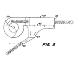
- a pre-cleaner is provided below the blower, which can be in the form of a conically shaped enclosed space 28, as can be seen in FIGS. 2 to 4, or in the form of a separating centrifuge 29 in accordance with FIG. 5.
- the precleaner in the form of the enclosed space 28 consists of an elongate hollow part 30 with a conical surface 32 on one side Angle with a perpendicular can be between 5 and 10 ° and is denoted by e in Fig. 3 ⁇ . Depending on the length of the hollow part 30, other angles can also be used. Length and angle depend on the space available.
- the conical surface 32 extends over the entire length of the hollow part from an inlet opening 34 at the upper end to a first outlet 36 at the lower end. The latter is designed so that its cross-sectional area is smaller than that of the inlet opening 34. However, the outlet and inlet opening are aligned with one another.
- a curved shape of the hollow part 30 is also conceivable if the pressure drop does not render the system ineffective.
- the entire hollow part 30, as shown in FIG. 2, can also be designed as a truncated cone. In any case, the cross-sectional area of the hollow part should decrease from the inlet opening 34 to the outlet 36, so that the air speed remains constant or approximately constant in the longitudinal direction.
- the hollow part 30 is equipped in the region of its conical surface with a second outlet 38, which consists of a multiplicity of openings 40 separated by ribs 42.
- the openings 40 are thus at a distance from one another and the ribs can expediently be connected to the hollow part 30.
- the openings are evenly distributed over the entire length of the hollow part, and the ribs in the hollow part are directed downward at an angle 0 (FIG. 4) of 10 to 45 ° or preferably 20 to 25 °.
- the inner ends of the ribs are at a greater distance from the inlet opening than their outer end.
- the diameters of the openings can vary, for practical reasons they should be about the same size and each should be about the cross section of the first outlet 36 correspond. All of the openings together should have a larger diameter than the cross-sectional area of the inlet opening 34, since this reduces the pressure drop in the air flowing through the hollow part 30.
- the ribs 42 arranged as described above force part of the air flowing through the hollow part to change direction, namely at an angle of more than 90 ° and less than 180 °.
- the ribs 42 are flat and their opposite surfaces cause the direction of the air to change in one direction only, so that the pressure drop in the hollow part 30 can be reduced to a minimum. Since the air sucked in by the blower 26 and flowing into the hollow part 30 has a pressure above the atmospheric pressure prevailing outside the cabin, approximately 85 to 90% of the air is discharged via the ribs 42 through the openings 40. Due to the sudden change of direction, the diverted part of the air is freed of its dirt particles, etc., since the inherent moment causes the dirt particles to be roughly in a straight, i.e.
- the particles continue to fly or fall in a non-derived direction. These are carried along by the approximately 10 to 15% of the non-redirected air and pass with this smaller part of the air through the first outlet 36, which in turn, as can be seen from FIG. 2, is open to the atmosphere. These particles then get back into the atmosphere. Since the pressure in the hollow part is higher than that prevailing immediately behind the first outlet, the particles will emerge from the hollow part simply by the pressure difference existing at the first outlet.
- the cleaned air flow passing through the openings 40 hits, as can be seen in FIG. 2, a filter 44 made of paper. This lies downstream with respect to the hollow part 30 and filters out any dirt particles etc. that are still present (approximately 5 to 10%, if at all).
- This air flow then arrives in a mixing zone 46, in which it mixes with air from the room 14.
- This air enters the mixing zone 46 through a second filter 48 on the partition, which serves to clean the used cabin air, which may contain tobacco smoke, etc., accordingly.
- the air from the mixing zone 46 is passed on via a processing mechanism 50 with a heater 52 and a cooling unit 54.
- the proportion of the air that is conducted via the heater 52 or the cooling unit 54 depends on regulating means 56, for example pivotable flaps or doors, which can be operated by hand or mechanically.
- the air is drawn in through filters 44 and 48 and the treatment mechanism via a second fan 58.
- the second fan 58 can be designed in several stages and thus suck in different amounts of air. It is connected in series with the first blower 26, thus assists the first blower in the passage of air through the filter 44 and conveys the air in the duct ducts 22 to a wide variety of air nozzles in the space 14 in the interior of the cabin.
- the first blower 26 is also arranged upstream.
- Separating centrifuges of this type can be designed as cylindrical hollow parts, two or more hollow parts generally being aligned parallel to one another and having one or more inner spirals. As a result, the heavier dirt particles etc. are against the outer periphery of the Separating centrifuge 29 pressed by the centrifugal force, whereas a cleaned air flow is conveyed in the longitudinal direction up to an outlet 60 at the end.
- the separating centrifuge 29 is further provided with a second outlet 62 in the form of many openings machined into its periphery, through which dirt particles and about 10% of the air flow get into a dirt box 64.
- This is conical, tapers downwards to a narrow opening 66, which in turn is open to the atmosphere.
- This L uftfiltersystem operates similarly, as to the F ig. 2 to 4. Again, the pressure in the separation centrifuge and at outlet 62 is higher than the atmospheric pressure. The pressure difference at the outlet 62 causes the dirt particles to easily escape from the dirt box 64 into the atmosphere.
- Both pre-cleaners have in common that the air flow containing the dirt particles can escape into the atmosphere without additional aids. This causes the blower 26 arranged in front of the precleaner, which also contributes to keeping the pressure drop in the precleaner as small as possible and that the precleaners are also constantly cleaned. As a result, the conventional filters 44 and 48 provided in the air filter system have a longer service life and the maintenance intervals can be increased.
- Louvers 68 or a sieve can still be installed at the inlet of the feed chute 24, so that larger foreign objects, such as stones, leaves, grasses, etc., are used in the areas where agricultural tractors or similar working vehicles are used Witness work, always be whirled up, can not enter the feed slot 24.
- air filter system described above can also be used to the same advantage in stationary devices or facilities.
Applications Claiming Priority (2)
| Application Number | Priority Date | Filing Date | Title |
|---|---|---|---|
| US49531983A | 1983-05-16 | 1983-05-16 | |
| US495319 | 1983-05-16 |
Publications (1)
| Publication Number | Publication Date |
|---|---|
| EP0125620A1 true EP0125620A1 (fr) | 1984-11-21 |
Family
ID=23968177
Family Applications (1)
| Application Number | Title | Priority Date | Filing Date |
|---|---|---|---|
| EP84105231A Withdrawn EP0125620A1 (fr) | 1983-05-16 | 1984-05-09 | Système de filtrage d'air |
Country Status (7)
| Country | Link |
|---|---|
| EP (1) | EP0125620A1 (fr) |
| JP (1) | JPS59225719A (fr) |
| BR (1) | BR8402282A (fr) |
| DK (1) | DK241284A (fr) |
| ES (1) | ES8505081A1 (fr) |
| NO (1) | NO841879L (fr) |
| ZA (1) | ZA843650B (fr) |
Cited By (9)
| Publication number | Priority date | Publication date | Assignee | Title |
|---|---|---|---|---|
| EP0226807A2 (fr) * | 1985-12-23 | 1987-07-01 | Hagenuk Gmbh | Dispositif de traitement de l'air pour la climatisation de véhicules |
| DE3716243A1 (de) * | 1987-05-15 | 1988-11-24 | Draegerwerk Ag | Filteranordnung zur reinhaltung beluefteter fahrzeuginnenraeume |
| DE4001148A1 (de) * | 1990-01-17 | 1991-07-18 | Deere & Co | Belueftungseinrichtung fuer fahrzeugkabine |
| AU623053B2 (en) * | 1990-03-26 | 1992-04-30 | Michael John Kindley | Canopy and blower assembly for vehicles |
| US5267605A (en) * | 1990-09-06 | 1993-12-07 | Doty Scientific, Inc. | Microtube array space radiator |
| EP1066995A1 (fr) * | 1999-07-09 | 2001-01-10 | Clark Equipment Company | Installation de chauffage, ventilation et climatisation pour véhicule de chargement à direction par dérapage |
| CN102530000A (zh) * | 2012-02-13 | 2012-07-04 | 株洲时代电子技术有限公司 | 一种电传动钢轨打磨车通风装置和系统及其方法 |
| EP2711216A3 (fr) * | 2012-09-21 | 2014-07-02 | MAN Truck & Bus AG | Dispositif d'aspiration pour une installation de chauffage et/ou de climatisation dans un véhicule automobile, notamment dans un véhicule utilitaire |
| EP2927031A3 (fr) * | 2014-03-31 | 2015-10-14 | CLAAS Selbstfahrende Erntemaschinen GmbH | Cabine de conducteur d'une machine-outil à usage agricole ou dans les travaux publics |
Citations (8)
| Publication number | Priority date | Publication date | Assignee | Title |
|---|---|---|---|---|
| US2076815A (en) * | 1934-02-07 | 1937-04-13 | Fulweiler John Edwin | Separating system and method |
| US2182862A (en) * | 1934-04-10 | 1939-12-12 | Thomas B Allardice | Separating method and apparatus |
| US2712858A (en) * | 1952-08-19 | 1955-07-12 | Research Corp | Apparatus for separating suspended materials from gases |
| US2787334A (en) * | 1953-11-07 | 1957-04-02 | Linderoth Erik Torvald | Electrostatic dust separators |
| FR1289861A (fr) * | 1960-07-18 | 1962-04-06 | Howden James & Co Ltd | Séparateur de poussière |
| DE1135868B (de) * | 1960-07-16 | 1962-09-06 | Hugo Petersen Fa | Verfahren zur Abscheidung von Schwefelsaeurenebeln aus Gasen |
| DE1407952A1 (de) * | 1964-02-28 | 1969-03-13 | Farr Co | Vorrichtung zum Abscheiden von Staub aus gasfoermigen,stroemenden Medien und Verfahren zu deren Herstellung |
| EP0042597A2 (fr) * | 1980-06-23 | 1981-12-30 | Deere & Company | Distributeur d'air |
-
1984
- 1984-05-09 EP EP84105231A patent/EP0125620A1/fr not_active Withdrawn
- 1984-05-10 NO NO841879A patent/NO841879L/no unknown
- 1984-05-14 ES ES532482A patent/ES8505081A1/es not_active Expired
- 1984-05-15 ZA ZA843650A patent/ZA843650B/xx unknown
- 1984-05-15 BR BR8402282A patent/BR8402282A/pt unknown
- 1984-05-16 JP JP59098448A patent/JPS59225719A/ja active Pending
- 1984-05-16 DK DK241284A patent/DK241284A/da not_active Application Discontinuation
Patent Citations (8)
| Publication number | Priority date | Publication date | Assignee | Title |
|---|---|---|---|---|
| US2076815A (en) * | 1934-02-07 | 1937-04-13 | Fulweiler John Edwin | Separating system and method |
| US2182862A (en) * | 1934-04-10 | 1939-12-12 | Thomas B Allardice | Separating method and apparatus |
| US2712858A (en) * | 1952-08-19 | 1955-07-12 | Research Corp | Apparatus for separating suspended materials from gases |
| US2787334A (en) * | 1953-11-07 | 1957-04-02 | Linderoth Erik Torvald | Electrostatic dust separators |
| DE1135868B (de) * | 1960-07-16 | 1962-09-06 | Hugo Petersen Fa | Verfahren zur Abscheidung von Schwefelsaeurenebeln aus Gasen |
| FR1289861A (fr) * | 1960-07-18 | 1962-04-06 | Howden James & Co Ltd | Séparateur de poussière |
| DE1407952A1 (de) * | 1964-02-28 | 1969-03-13 | Farr Co | Vorrichtung zum Abscheiden von Staub aus gasfoermigen,stroemenden Medien und Verfahren zu deren Herstellung |
| EP0042597A2 (fr) * | 1980-06-23 | 1981-12-30 | Deere & Company | Distributeur d'air |
Cited By (14)
| Publication number | Priority date | Publication date | Assignee | Title |
|---|---|---|---|---|
| EP0226807A3 (fr) * | 1985-12-23 | 1987-09-09 | Hagenuk Gmbh | Dispositif de traitement de l'air pour la climatisation de véhicules |
| EP0226807A2 (fr) * | 1985-12-23 | 1987-07-01 | Hagenuk Gmbh | Dispositif de traitement de l'air pour la climatisation de véhicules |
| DE3716243A1 (de) * | 1987-05-15 | 1988-11-24 | Draegerwerk Ag | Filteranordnung zur reinhaltung beluefteter fahrzeuginnenraeume |
| AU631040B2 (en) * | 1990-01-17 | 1992-11-12 | Deere & Company | Ventilating arrangement for the cab of a vehicle |
| DE4001148A1 (de) * | 1990-01-17 | 1991-07-18 | Deere & Co | Belueftungseinrichtung fuer fahrzeugkabine |
| EP0438076A2 (fr) * | 1990-01-17 | 1991-07-24 | Deere & Company | Distributeur d'air pour cabines de véhicules |
| EP0438076A3 (en) * | 1990-01-17 | 1991-12-27 | Deere & Company | Air distributing arrangement for vehicle cabins |
| AU623053B2 (en) * | 1990-03-26 | 1992-04-30 | Michael John Kindley | Canopy and blower assembly for vehicles |
| US5267605A (en) * | 1990-09-06 | 1993-12-07 | Doty Scientific, Inc. | Microtube array space radiator |
| EP1066995A1 (fr) * | 1999-07-09 | 2001-01-10 | Clark Equipment Company | Installation de chauffage, ventilation et climatisation pour véhicule de chargement à direction par dérapage |
| US6223807B1 (en) | 1999-07-09 | 2001-05-01 | Clark Equipment Company | Heating, ventilating and air conditioning system for a skid steer loader |
| CN102530000A (zh) * | 2012-02-13 | 2012-07-04 | 株洲时代电子技术有限公司 | 一种电传动钢轨打磨车通风装置和系统及其方法 |
| EP2711216A3 (fr) * | 2012-09-21 | 2014-07-02 | MAN Truck & Bus AG | Dispositif d'aspiration pour une installation de chauffage et/ou de climatisation dans un véhicule automobile, notamment dans un véhicule utilitaire |
| EP2927031A3 (fr) * | 2014-03-31 | 2015-10-14 | CLAAS Selbstfahrende Erntemaschinen GmbH | Cabine de conducteur d'une machine-outil à usage agricole ou dans les travaux publics |
Also Published As
| Publication number | Publication date |
|---|---|
| JPS59225719A (ja) | 1984-12-18 |
| DK241284A (da) | 1984-11-17 |
| ES532482A0 (es) | 1985-04-16 |
| ZA843650B (en) | 1985-12-24 |
| ES8505081A1 (es) | 1985-04-16 |
| DK241284D0 (da) | 1984-05-16 |
| BR8402282A (pt) | 1984-12-26 |
| NO841879L (no) | 1984-11-19 |
Similar Documents
| Publication | Publication Date | Title |
|---|---|---|
| EP0178316B1 (fr) | Separateur cyclone | |
| DE2805017A1 (de) | Vorrichtung zum trennen bzw. ausscheiden von bestandteilen eines gutes der tabakverarbeitenden industrie aus luft | |
| DE2802369A1 (de) | Filtervorrichtung zum filtern von durch staub und faserabfaelle verunreinigter luft | |
| EP0624310A1 (fr) | Dispositif de nettoyage en particulier pour moissonneuse-batteuse | |
| DE60014311T2 (de) | Zyklon-staubsammelvorrichtung | |
| DE3006831A1 (de) | Vorrichtung zum abscheiden von verunreinigungen aus baumwoll-faserflocken | |
| DE2106134C3 (de) | Windsichter für Schnittabak | |
| DE1404894A1 (de) | Vorrichtung zum Auffangen und Ausscheiden von Faserflug und Staub im Abluftkanal vonBelueftungs- oder Klimaanlagen in Textilbetrieben,insbesondere Spinnereien und Webereien | |
| EP0125620A1 (fr) | Système de filtrage d'air | |
| DE112016000194B4 (de) | Windkanalumlauf-Sichtvorrichtung für Schüttmaterial | |
| DE102015109999A1 (de) | Luftfilteranlage | |
| DE3912077C2 (de) | Reinigungsmaschine fuer koerniges reinigungsgut | |
| DE602004012047T2 (de) | Abfalltrennvorrichtung für Staubsauger | |
| DE2158338C3 (de) | Verfahren und Einrichtung zum Reinigen von Filterzellen | |
| WO2000018490A1 (fr) | Procede et dispositif pour enlever des particules contenues dans un fluide | |
| EP0282048B1 (fr) | Dispositif pour le traitement de matériaux de recyclage, de préférence de décombres | |
| DE2650617C2 (de) | Verfahren und Vorrichtung zum Reinigen und Sortieren von Getreide, Sämereien oder dergleichen Nutzgut | |
| EP0683970A2 (fr) | Dispositif soufflant de nettoyage pour batteuse | |
| EP0392453B1 (fr) | Séparateur centrifuge | |
| DE837981C (de) | Verfahren und Vorrichtung zur Trockenentstaubung von Kohlen und aehnlichen Stoffen | |
| DE1927262B1 (de) | Reinigungsvorrichtung fuer Maehdrescher | |
| EP3569322A1 (fr) | Dispositif de séparation | |
| DE2327838A1 (de) | Anordnung zum abscheiden von tabakpartikeln in einer pneumatischen foerdereinrichtung | |
| DE10139295C1 (de) | Gerät zur Abscheidung von Fremdsubstanzen aus einem Luftstrom | |
| EP2332626B1 (fr) | Dispositif de séparation d'impuretés à partir d'un flux d'air |
Legal Events
| Date | Code | Title | Description |
|---|---|---|---|
| PUAI | Public reference made under article 153(3) epc to a published international application that has entered the european phase |
Free format text: ORIGINAL CODE: 0009012 |
|
| AK | Designated contracting states |
Designated state(s): AT BE CH DE FR GB IT LI NL SE |
|
| 17P | Request for examination filed |
Effective date: 19841123 |
|
| ITCL | It: translation for ep claims filed |
Representative=s name: LENZI & C. |
|
| TCNL | Nl: translation of patent claims filed | ||
| EL | Fr: translation of claims filed | ||
| STAA | Information on the status of an ep patent application or granted ep patent |
Free format text: STATUS: THE APPLICATION IS DEEMED TO BE WITHDRAWN |
|
| 18D | Application deemed to be withdrawn |
Effective date: 19860220 |
|
| RIN1 | Information on inventor provided before grant (corrected) |
Inventor name: DELANEY, WILLIAM ROBERT Inventor name: SHIRK, THOMAS MICHAEL Inventor name: HOSFORD, GREGORY SANDER |