EP0125427B1 - Trommelförderer - Google Patents
Trommelförderer Download PDFInfo
- Publication number
- EP0125427B1 EP0125427B1 EP84102946A EP84102946A EP0125427B1 EP 0125427 B1 EP0125427 B1 EP 0125427B1 EP 84102946 A EP84102946 A EP 84102946A EP 84102946 A EP84102946 A EP 84102946A EP 0125427 B1 EP0125427 B1 EP 0125427B1
- Authority
- EP
- European Patent Office
- Prior art keywords
- bearing bush
- drum
- bearing
- type conveyor
- rake pipe
- Prior art date
- Legal status (The legal status is an assumption and is not a legal conclusion. Google has not performed a legal analysis and makes no representation as to the accuracy of the status listed.)
- Expired
Links
- 230000000295 complement effect Effects 0.000 claims abstract description 5
- 238000003306 harvesting Methods 0.000 claims abstract description 5
- 239000000463 material Substances 0.000 claims abstract description 5
- 239000000969 carrier Substances 0.000 description 2
- 239000004460 silage Substances 0.000 description 2
- 241001124569 Lycaenidae Species 0.000 description 1
- 238000005452 bending Methods 0.000 description 1
- 238000010276 construction Methods 0.000 description 1
- 235000011389 fruit/vegetable juice Nutrition 0.000 description 1
- 238000003780 insertion Methods 0.000 description 1
- 230000037431 insertion Effects 0.000 description 1
- 238000000034 method Methods 0.000 description 1
- 239000007779 soft material Substances 0.000 description 1
- 239000010902 straw Substances 0.000 description 1
Images
Classifications
-
- A—HUMAN NECESSITIES
- A01—AGRICULTURE; FORESTRY; ANIMAL HUSBANDRY; HUNTING; TRAPPING; FISHING
- A01D—HARVESTING; MOWING
- A01D90/00—Vehicles for carrying harvested crops with means for selfloading or unloading
- A01D90/02—Loading means
-
- A—HUMAN NECESSITIES
- A01—AGRICULTURE; FORESTRY; ANIMAL HUSBANDRY; HUNTING; TRAPPING; FISHING
- A01D—HARVESTING; MOWING
- A01D89/00—Pick-ups for loaders, chaff-cutters, balers, field-threshers, or the like, i.e. attachments for picking-up hay or the like field crops
- A01D89/001—Pick-up systems
- A01D89/002—Rotors
Definitions
- the present invention relates to a drum conveyor, in particular for self-loading harvesting wagons, according to the preamble of patent claim 1.
- Such self-loading harvesting wagons are particularly suitable for agricultural companies with a high proportion of fodder construction, both for hay salvage, straw salvage, daily fetching, juice silage and wilting silage.
- the feed to be transported is usually picked up by a pickup device and fed to a conveyor channel. it is then gripped by the drum conveyor and transported into the interior of the loading wagon.
- Such a drum conveyor has a multiplicity of rotatably mounted rake tubes, each of which is provided with a multiplicity of conveying tines which are arranged parallel to one another and at a distance from one another, which engage in the conveying channel during circulation and for transporting the feed stream into the interior of the loading wagon serve.
- the cargo fed to the conveyor channel is dosed in equal portions by the conveyor tines and guided into the loading area of the harvesting wagon in a uniform flow process.
- the conveyor tines are usually welded to the rake tubes, so that this must consist of soft and weldable material. However, this necessitates rapid wear at the bearing points, so that the entire conveyor rake had to be replaced up to now with appropriate wear of the rake tubes at the bearing points.
- the exchange of a complete funding rake is expensive and cumbersome.
- each tine carrier being made up of twist-proof individual pieces to its total length in order to increase the working width, and the connection points of the individual pieces of all tine carriers in each case in one common radial plane and are each rotatably supported and supported on the central shaft.
- split bearings are provided, each of which is fastened with an inner bearing shell to a support member which is freely rotatable on the central shafts.
- the support member is designed according to the number of tine carriers as a support cross or support star, the arms of which extend radially outward from a hub mounted on the central shaft and carry the inner bearing shells at their ends.
- split bearing bushes are also provided in the split bearings in a central radial plane for a sliding bearing of the shaft pieces.
- the object of the present invention is to provide a drum conveyor in which the rake tubes of the conveyor rakes are protected against wear so that they no longer have to be replaced.
- the advantage is achieved that no more wear now occurs due to the sliding of the bearing bush in the bearing housing on the computing tube itself.
- the rake tube can thus continue to be made of soft and weldable material, since wear now occurs on the bearing housing, which can be exchanged much cheaper than the entire conveyor rake.
- the bearing housing and the bearing bush are each divided in the middle, so that easy disassembly and replacement is made possible.
- the bearing bush In order to connect the bearing bush to the rake tube in a rotationally fixed manner, it can be provided along at least one edge with a profile which engages in a disk which is arranged next to the bearing and surrounds and is fastened to it with a complementary profile, so that it bears against a Relative rotation to the rake tube is secured.
- This profile can e.g. be a tooth profile that extends over the entire edge of the bearing bush and the locking washer.
- the profile can also consist of a plurality of semicircular recesses on the bearing bush, which interact with corresponding semicircular projections along the edge of the disk.
- the profile of the bearing bush consists of two diametrically opposed projections which are provided on both edges of the bearing bush and that the profile of the locking washer consists of corresponding recesses in which the projections engage.
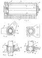
- two rake tubes 1, 2 are shown with attached conveyor tines 3, 4, which e.g. are welded on.
- the conveyor rakes are rotatably supported at their two ends on a drum holder 6, as is indicated by the two dashed circles 5, 5 '.
- the conveyor rakes can be e.g. perform a back-and-forth movement to move the feed towards the loader wagon.
- FIG. 2 shows an enlarged view of a first embodiment of a bearing point according to the invention, 7 being the computing tube.
- the computing tube is surrounded by a bearing bush 8 which is connected to it in a rotationally fixed manner and is arranged within a bearing housing 10 which is firmly connected to the holder 6.
- both the bearing bush 8 and the bearing housing 10 are divided in the center, so that easy insertion is possible.
- the bearing bush is e.g.
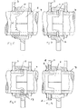
- Figures 4 and 5 show a second embodiment of a bearing according to the invention.
- the bearing bush 8 which is again divided in the middle along a line 12, has at its two edges two diametrically opposite projections 13, 14 which engage in corresponding recesses in the locking washer 11 formed on both sides here, so that since the locking washer 11 is rotationally fixed is connected to the computing tube 7, the bearing bush 8 is taken.
- wear occurs exclusively at the friction points between the bearing bush 8 and the bearing housing 10.
- the bearing bush 8 is provided along one edge with spaced-apart semicircular recesses 15 which engage in corresponding semicircular recesses of the locking washer, so that here also a rotationally fixed bearing on the bearing bush Computing tube 7 takes place.
- the bearing bush 8 is connected to the computing tube 7 via grooved pins 16 or welded-on bolts 16 which engage in corresponding openings in the computing tube 7.
- the bearing bush 8 is connected to the rake tube 7 via countersunk screws 17, these countersunk screws likewise engaging in openings of the rake tube 7 provided here with threads.
- the lock washer is omitted in the latter two exemplary embodiments, the load capacity of the rake tube at the bearing points for twisting and bending is lower due to the bores.
- FIG. 9 shows an embodiment in which the bearing bush 8 on the computing tube 7 is partially pushed under a welded-on ring 19 and secured with a set screw 18 e.g. with an internal hexagon and an annular cutting edge.
- a further possibility is to release the bearing bush at the ends and to bend it inwards, in which case they are supported in specially provided grooves.
- bearing bushes on the outer casing of the computing tube are arranged in a rotationally fixed manner, so that the rotation takes place between the outer diameter of the bearing bush and the inner surface of the bearing housing. If wear occurs at these points, the bearings can be replaced easily and inexpensively, whereas the conveyor rakes no longer show wear at the bearing points and consequently no longer need to be replaced.
- Bearing bush and bearing housing are made of a hardenable material and therefore have a longer service life than the conventionally mounted ends of the rake tubes made of soft material.
Landscapes
- Life Sciences & Earth Sciences (AREA)
- Environmental Sciences (AREA)
- Screw Conveyors (AREA)
Priority Applications (1)
| Application Number | Priority Date | Filing Date | Title |
|---|---|---|---|
| AT84102946T ATE22771T1 (de) | 1983-05-11 | 1984-03-16 | Trommelfoerderer. |
Applications Claiming Priority (2)
| Application Number | Priority Date | Filing Date | Title |
|---|---|---|---|
| DE19833317302 DE3317302A1 (de) | 1983-05-11 | 1983-05-11 | Trommelfoerderer |
| DE3317302 | 1983-05-11 |
Publications (2)
| Publication Number | Publication Date |
|---|---|
| EP0125427A1 EP0125427A1 (de) | 1984-11-21 |
| EP0125427B1 true EP0125427B1 (de) | 1986-10-15 |
Family
ID=6198790
Family Applications (1)
| Application Number | Title | Priority Date | Filing Date |
|---|---|---|---|
| EP84102946A Expired EP0125427B1 (de) | 1983-05-11 | 1984-03-16 | Trommelförderer |
Country Status (3)
| Country | Link |
|---|---|
| EP (1) | EP0125427B1 (enExample) |
| AT (1) | ATE22771T1 (enExample) |
| DE (1) | DE3317302A1 (enExample) |
Families Citing this family (1)
| Publication number | Priority date | Publication date | Assignee | Title |
|---|---|---|---|---|
| DE3733210C1 (en) * | 1987-10-01 | 1989-02-23 | Welger Geb | Drum conveyor, in particular receiving drum for stalked material |
Family Cites Families (3)
| Publication number | Priority date | Publication date | Assignee | Title |
|---|---|---|---|---|
| DE1893335U (de) * | 1963-04-17 | 1964-05-21 | Steyr Daimler Puch Ag | An die stirnseite eines fahrzeuges angeordnete ladevorrichtung fuer halmgut od. dgl. |
| DE2006923C3 (de) * | 1970-02-16 | 1975-04-10 | Fa. Heinrich Wilhelm Dreyer, 4509 Wittlage | Aufnahmetrommel für gemähtes halm- oder blattartiges Erntegut |
| SU626722A1 (ru) * | 1975-04-18 | 1978-10-05 | Ростовский-На-Дону Институт Сельскохозяйственного Машиностроения | Мотовило селькохоз йственной уборочной машины |
-
1983
- 1983-05-11 DE DE19833317302 patent/DE3317302A1/de active Granted
-
1984
- 1984-03-16 EP EP84102946A patent/EP0125427B1/de not_active Expired
- 1984-03-16 AT AT84102946T patent/ATE22771T1/de not_active IP Right Cessation
Also Published As
| Publication number | Publication date |
|---|---|
| DE3317302A1 (de) | 1984-11-15 |
| EP0125427A1 (de) | 1984-11-21 |
| ATE22771T1 (de) | 1986-11-15 |
| DE3317302C2 (enExample) | 1993-06-24 |
Similar Documents
| Publication | Publication Date | Title |
|---|---|---|
| EP0903077B1 (de) | Aufnahmeeinheit für Erntegut | |
| EP1010363B1 (de) | Maschine zum Mähen und Häckseln von Mais und dgl. stengelartigem Erntegut | |
| DE2736005A1 (de) | Reihenvorsatzgeraet fuer feldhaecksler | |
| EP1008291A1 (de) | Vorsatzgerät für Erntemaschine | |
| DE19811449C1 (de) | Fördereinrichtung für Erntemaschinen | |
| EP0958732B1 (de) | Aufnehmer | |
| DE8526201U1 (de) | Schneid- und Förderschnecke | |
| DE1507295C3 (de) | Rechrad | |
| EP0125427B1 (de) | Trommelförderer | |
| DE3621995A1 (de) | Aufsammler fuer halmguterntemaschinen | |
| EP3669637B1 (de) | Landwirtschaftliche erntemaschine mit fördertrommel | |
| DE2713502A1 (de) | Querfoerdereinrichtung auf einem maehdrescher-schneidtisch | |
| DE3028140C2 (de) | Ladewagen für landwirtschaftliche Massengüter | |
| DE19501382B4 (de) | Lade- und Fördervorrichtung eines Selbstladewagens | |
| DE102020117155A1 (de) | Aufnahmevorrichtung mit in Gruppen angeordneten Förderzinken | |
| EP3932177B1 (de) | Aufnahmevorrichtung mit auf einer trommel befestigten förderzinken | |
| DE3212123C1 (de) | Aufnahmetrommel fuer gemaehtes halm- oder blattartiges Erntegut | |
| BE1023767B1 (de) | Förderscheibe für einen Förderrotor zur Erntegutförderung in einer landwirtschaftlichen Erntemaschine | |
| DE3804598A1 (de) | Querfoerderschnecke fuer einen maeh- oder maiserntevorsatz | |
| DE3215974C2 (de) | Ladewagen | |
| DE2730308C3 (de) | Ladewagen für Halmgut | |
| DE102006061010A1 (de) | Erntemaschine | |
| DE3324898A1 (de) | Schneid- und zufuehreinrichtung fuer eine gezogene oder fuer den dreipunktanbau am schlepper vorgesehene maschine zum ernten von mais o.dgl. stengelartigem erntegut | |
| AT400791B (de) | Ladewagen für landwirtschaftliches halmgut | |
| DE19939168A1 (de) | Vorsatzgerät zum Ernten von stengeligem Erntegut |
Legal Events
| Date | Code | Title | Description |
|---|---|---|---|
| PUAI | Public reference made under article 153(3) epc to a published international application that has entered the european phase |
Free format text: ORIGINAL CODE: 0009012 |
|
| AK | Designated contracting states |
Designated state(s): AT CH LI NL |
|
| 17P | Request for examination filed |
Effective date: 19850118 |
|
| RIN1 | Information on inventor provided before grant (corrected) |
Inventor name: SILBER, WILHELM Inventor name: SCHWEIZER, ROBERT Inventor name: BOTTLANG, ERWIN Inventor name: SCHAIBLE, SIEGFRIED, DIPL.-ING. |
|
| GRAA | (expected) grant |
Free format text: ORIGINAL CODE: 0009210 |
|
| AK | Designated contracting states |
Kind code of ref document: B1 Designated state(s): AT CH LI NL |
|
| REF | Corresponds to: |
Ref document number: 22771 Country of ref document: AT Date of ref document: 19861115 Kind code of ref document: T |
|
| PLBE | No opposition filed within time limit |
Free format text: ORIGINAL CODE: 0009261 |
|
| STAA | Information on the status of an ep patent application or granted ep patent |
Free format text: STATUS: NO OPPOSITION FILED WITHIN TIME LIMIT |
|
| 26N | No opposition filed | ||
| REG | Reference to a national code |
Ref country code: CH Ref legal event code: PUE Owner name: GREENLAND GMBH & CO. KG |
|
| NLS | Nl: assignments of ep-patents |
Owner name: GREENLAND GMBH & CO. KG TE GOTTMADINGEN, BONDSREPU |
|
| PGFP | Annual fee paid to national office [announced via postgrant information from national office to epo] |
Ref country code: CH Payment date: 19960220 Year of fee payment: 13 |
|
| PGFP | Annual fee paid to national office [announced via postgrant information from national office to epo] |
Ref country code: NL Payment date: 19960222 Year of fee payment: 13 |
|
| PG25 | Lapsed in a contracting state [announced via postgrant information from national office to epo] |
Ref country code: LI Effective date: 19970331 Ref country code: CH Effective date: 19970331 |
|
| PG25 | Lapsed in a contracting state [announced via postgrant information from national office to epo] |
Ref country code: NL Effective date: 19971001 |
|
| REG | Reference to a national code |
Ref country code: CH Ref legal event code: PL |
|
| NLV4 | Nl: lapsed or anulled due to non-payment of the annual fee |
Effective date: 19971001 |
|
| PGFP | Annual fee paid to national office [announced via postgrant information from national office to epo] |
Ref country code: AT Payment date: 19990225 Year of fee payment: 16 |
|
| PG25 | Lapsed in a contracting state [announced via postgrant information from national office to epo] |
Ref country code: AT Free format text: LAPSE BECAUSE OF NON-PAYMENT OF DUE FEES Effective date: 20000316 |