EP0125035A2 - Méthode et système pour transporter des objets - Google Patents
Méthode et système pour transporter des objets Download PDFInfo
- Publication number
- EP0125035A2 EP0125035A2 EP84302425A EP84302425A EP0125035A2 EP 0125035 A2 EP0125035 A2 EP 0125035A2 EP 84302425 A EP84302425 A EP 84302425A EP 84302425 A EP84302425 A EP 84302425A EP 0125035 A2 EP0125035 A2 EP 0125035A2
- Authority
- EP
- European Patent Office
- Prior art keywords
- container
- panel
- modules
- module
- container modules
- Prior art date
- Legal status (The legal status is an assumption and is not a legal conclusion. Google has not performed a legal analysis and makes no representation as to the accuracy of the status listed.)
- Withdrawn
Links
- 238000000034 method Methods 0.000 title claims abstract description 13
- 229910000746 Structural steel Inorganic materials 0.000 description 2
- 239000004744 fabric Substances 0.000 description 1
- 239000010985 leather Substances 0.000 description 1
- 238000012986 modification Methods 0.000 description 1
- 230000004048 modification Effects 0.000 description 1
- 238000012856 packing Methods 0.000 description 1
- 239000012858 resilient material Substances 0.000 description 1
- 210000002105 tongue Anatomy 0.000 description 1
Images

Classifications
-
- B—PERFORMING OPERATIONS; TRANSPORTING
- B65—CONVEYING; PACKING; STORING; HANDLING THIN OR FILAMENTARY MATERIAL
- B65D—CONTAINERS FOR STORAGE OR TRANSPORT OF ARTICLES OR MATERIALS, e.g. BAGS, BARRELS, BOTTLES, BOXES, CANS, CARTONS, CRATES, DRUMS, JARS, TANKS, HOPPERS, FORWARDING CONTAINERS; ACCESSORIES, CLOSURES, OR FITTINGS THEREFOR; PACKAGING ELEMENTS; PACKAGES
- B65D88/00—Large containers
- B65D88/02—Large containers rigid
- B65D88/10—Large containers rigid parallelepipedic
-
- B—PERFORMING OPERATIONS; TRANSPORTING
- B65—CONVEYING; PACKING; STORING; HANDLING THIN OR FILAMENTARY MATERIAL
- B65D—CONTAINERS FOR STORAGE OR TRANSPORT OF ARTICLES OR MATERIALS, e.g. BAGS, BARRELS, BOTTLES, BOXES, CANS, CARTONS, CRATES, DRUMS, JARS, TANKS, HOPPERS, FORWARDING CONTAINERS; ACCESSORIES, CLOSURES, OR FITTINGS THEREFOR; PACKAGING ELEMENTS; PACKAGES
- B65D88/00—Large containers
- B65D88/02—Large containers rigid
- B65D88/12—Large containers rigid specially adapted for transport
-
- B—PERFORMING OPERATIONS; TRANSPORTING
- B65—CONVEYING; PACKING; STORING; HANDLING THIN OR FILAMENTARY MATERIAL
- B65D—CONTAINERS FOR STORAGE OR TRANSPORT OF ARTICLES OR MATERIALS, e.g. BAGS, BARRELS, BOTTLES, BOXES, CANS, CARTONS, CRATES, DRUMS, JARS, TANKS, HOPPERS, FORWARDING CONTAINERS; ACCESSORIES, CLOSURES, OR FITTINGS THEREFOR; PACKAGING ELEMENTS; PACKAGES
- B65D88/00—Large containers
- B65D88/54—Large containers characterised by means facilitating filling or emptying
Definitions
- This invention relates to a method and system for transporting articles such as freight and furniture.
- the furniture is usually moved by loading it carefully into a furniture van and transporting it to its new location.
- the furniture is stacked in the rear of the van and must be unstacked piece by piece when it arrives at its new location.
- This method of transporting furniture is time consuming, particularly when the furniture is to be stored since it will be again necessary to load the furniture van piece by piece when the furniture is to be taken out of storage.
- U.S. patent Nos. 2,761,581 and 3,004,682 disclose methods and systems for transporting articles wherein individual containers are loaded and consecutively closed by swinging doors.
- the swinging doors are believed to be complicated and expensive and to also impair loading and unloading of the containers.
- the present invention may be said to reside in a method of transporting articles comprising the steps of arranging a plurality of container modules on a vehicle, such that it is possible to pass through the container modules, loading articles into a rear one of said plurality of container modules, closing said rear container module, loading furniture into a container adjacent the rear container module and closing the adjacent container module and so on until all or a desired number of container modules have been filled, said container modules being closed by the steps of locating bracing means in a rear open side of the container modules and locating a panel means in the rear open side adjacent the bracing means and locating a panel means in the front open side of the container modules and locating bracing means adjacent the panel means in the front side so that the bracing means is exterior of the container.
- the invention may also be said to reside in a system for transporting articles, said system comprising a plurality of container modules which may be arranged in line on a vehicle, said plurality of container modules having at least two open sides such that it is possible to pass through the container modules so that articles may be loaded into a rear container module by passing through the other container modules and the rear container module can then be closed, and wherein an adjacent container module can then be located and closed and so on until all or a desired number of container modules are filled, said container modules having a rear panel means and a front panel means to close the container modules and bracing means arranged adjacent the front and rear panel means and the exterior of the container modules.
- bracing means and panels can be completely removed from the modules and replaced to close the modules they do not impair unloading or loading of the modules and the bracing and panels are relatively inexpensive to provide.
- the invention may also be said to reside in a container module, said container module having a pair of side walls, a floor, a roof, a back and a front, at least said back and said front being removable from the container module and said back comprising a removable rear panel means and removable bracing means exterior of said container module and the front wall comprising a removable front panel means and removable bracing means exterior of said container module.
- the containers can be stored with the furniture therein and it is not necessary to handle and move individual items of furniture into and out of storage. Since the furniture itself is not handled the likelihood of damaging the furniture during unloading for storage and relaying from storage is greatly reduced.
- the rear panel means comprises a first portion and a second portion hinged together so that the panel can be folded so that it can easily be moved into a container module.
- the front panel means comprises a first panel portion and a separate second panel portion, the first panel portion having a hasp and the second panel portion having a staple so that when the panel portions are in place in a container module the hasp fits over the staple and may be closed by a pin.
- the bracing means comprises a cross brace having a plurality of pin means, said pin means being adapted to be received in slots or sleeves on the container modules to fix the bracing means to the container modules and preferably the bracing means includes the said pin which is fitted into the staple on the second panel.
- a platform is provided with a plurality of grooves for receiving the tynes of a forklift truck such that container modules can be slid onto the platform and then lifted up by means of the forklift truck.
- the said platform may form a tailgate of a truck or the like for transporting the container modules or may be attached to the truck when it arrives at its destination.
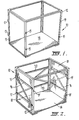
- a plurality of container modules 10 each of which is in generally modular form include a rectangular frame 12 having a floor 14.
- the frame 12 is preferably formed of angle iron.
- the container is dimensioned to fit into a furniture moving vehicle 50 (see Figure 6) or into a conventional freight container, and is about 8ft long, 3ft wide and about 7ft high.
- the container modules 10 preferably include a roof (not shown).
- the container modules 10 are provided with bracing 16 on their outer sides and the sides may be closed with panels 18. Preferably five containers 10a to 10e (see Figure 6) are loaded into the furniture storage vehicle after the bracing 16 and panels 18 have been fitted.
- the bracing 16 and panel 18 may be permanently fixed in the container module.
- the front outer surface of the frame 12 includes four slots or sleeves 15 and the rear inner surface of the frame 12 also includes four slots or sleeves 17 (only two of which are shown in Figure 1).
- the containers are arranged with their longitudinal axis perpendicular to the longitudinal axis of the vehicle and substantially fill the entire storage area of the vehicle.
- the container 10e is- loaded adjacent to the front of the vehicle 50 and becomes a rear container since the access to the container 10 is via doors (not shown) at the rear 52 of the vehicle 50.
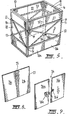
- the container 10e is preferably provided with rear bracing 20 see Figures 2 to 4 and 10 and the rear panel 22 (see Figures 4 and 8) before it is loaded onto the vehicle 50.
- the rear container module 10e be the same as the other container modules so that it is not necessary to provide a special container module for the position at the front of the vehicle 50.
- the containers 10a to 10e are arranged in the vehicle 50 with side panels 18 and suitable bracing 16.
- the rear bracing 20 best seen in Figure 8 is then fitted to the rear wall of the container module 10e.
- the brace 20 shown in Figure 10 comprises a cross member 25 and an upper and lower member 27 and 29.
- Four pins or tongues 31 project downwardly from each end of the upper and lower members 27 and 29 and a central pin 33 is arranged at the intersection of the members 25.
- the brace 20 is then fitted to the rear wall of the container module 10e by locating the pins 31 in the sleeves or slots 17 on the inner surface of the frame .12.
- the upper pins 31 may be made longer than the lower pins 31 so that they can first be located in a sleeve or slot 17 and therefore the brace will be held in the rear wall and then the brace can be lowered to locate the lower pins 31 into their respective sleeve or slot 17.
- the pin 33 has no function when the brace 20 is used in the rear wall of a container module.
- the rear panel 22 is formed in two sections 21a and 21b which are joined by a resilient material such as leather or fabric 23 so that the panels 21a and 21b can be folded towards each other to facilitate their positioning in the container 10e.
- the floor 14 of the container module is spaced slightly from the lower frame member 12 so that the panel 22 can slip between the angle iron frame member 12 and the floor 14. The panel 22 will therefore be held in place by the bracing 20 and the frame 12 and will be prevented from falling into the container module by the furniture or other articles which are loaded into the container module.
- a front panel 26 is located on the front of the container 10e.
- the front panel 26 is formed in two parts 26a and 26b.
- the part 26a has a hasp 26c and the part 26b has a staple 26d.
- the panel 26 is fitted by first locating the part 26b behind the front frame member 12 and pushing it to one side so that the staple is generally centrally in the container module.
- the panel 26a is then fitted behind the frame member 12 and pushed to the other side so that the hasp 26c can engage the staple 26d with the staple projecting through the open portion of the hasp 26c.
- Bracing 20 described with reference to Figure 10 is then fixed to the frame 12 by locating the pins 31 in the slots or sleeves 15 and the pin 33 is arranged to project through the staple 26d and wire seal (not shown) may be passed through a hole in the pin 33 to secure the pin in the staple so that the brace 20 can not be lifted out of the slots or sleeves 15 without first breaking the wire seal.
- the container 10e is completely closed with the interior walls of the container being formed by panels 18, 22 and 26 which provide a smooth surface and do not damage the contents of the container module.
- the other containers are filled and closed in the same manner. Once the container modules have been filled and closed they each form a giant carton suitably braced and may be loaded and unloaded by a forklift truck.
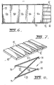
- a platform 40 In order to unload and load containers into the vehicle a platform 40 is provided. As best seen in Figure 7 the platform has a plurality of grooves 42.
- the platform 40 may form the tailgate of the vehicle 50 as shown in Figure 6 or simply may be connected to the vehicle when the vehicle reaches its destination.
- the platform 40 In order to remove containers from the vehicle the platform 40 is arranged as shown in Figure 6 so that it is horizontal and level with the floor of the vehicle 50.
- the platform 40 forming a tailgate it need only be swung down in the conventional manner in the case of the platform 40 forming a separate platform it can be connected to the rear of the vehicle by any suitable means.
- a chain (not shown) is connected to the container module 10a and by means of a forklift truck the container module 10a is draaged onto the platform 40.
- a forklift truck is then maneuvered into position such that the tynes of the forklift truck enter the grooves 42 beneath the container module 10a.
- the forklift truck may be a conventional forklift truck with two tynes or may be provided with four or more tynes to match the number of grooves 42 in the platform 40. Once the tynes have been located beneath the container 10a the container 10a is merely lifted by the forklift truck in the conventional manner and removed from the rear of the vehicle.
- the next container module 10b is dragged onto the platform 40 by means of the chain and forklift truck and is removed in the same manner. This continues until all the container modules have been removed from the vehicle.
- a pusher bar (not shown) which is attached to the front of the forklift truck the container module is then pushed into the vehicle 52.
- Other container modules are loaded in exactly, the same manner.
- the present invention can be used to move furniture from one house to another it is of most benefit when furniture is to be placed in storage since the furniture need not be unpacked from the containers 10 by merely stored in the containers.
- the containers are reloaded onto the vehicle 50 when the furniture is required and transported to its new location. Accordingly the furniture is not unloaded piece by piece when it is stored or reloaded piece by piece and the likelihood of damage to the furniture is therefore greatly reduced.
- the time taken to unload and reload the furniture at the storage location is greatly reduced since this task is performed by the abovementioned forklift trucks and accordingly the cost involved in transporting the furniture to and from the storage is also greatly reduced.
Landscapes
- Engineering & Computer Science (AREA)
- Mechanical Engineering (AREA)
- Loading Or Unloading Of Vehicles (AREA)
- Handcart (AREA)
- Warehouses Or Storage Devices (AREA)
- Pallets (AREA)
Applications Claiming Priority (2)
| Application Number | Priority Date | Filing Date | Title |
|---|---|---|---|
| AU920983 | 1983-05-06 | ||
| AU9209/83 | 1983-05-06 |
Publications (2)
| Publication Number | Publication Date |
|---|---|
| EP0125035A2 true EP0125035A2 (fr) | 1984-11-14 |
| EP0125035A3 EP0125035A3 (fr) | 1986-03-12 |
Family
ID=3699942
Family Applications (1)
| Application Number | Title | Priority Date | Filing Date |
|---|---|---|---|
| EP84302425A Withdrawn EP0125035A3 (fr) | 1983-05-06 | 1984-04-10 | Méthode et système pour transporter des objets |
Country Status (3)
| Country | Link |
|---|---|
| EP (1) | EP0125035A3 (fr) |
| JP (1) | JPS6040326A (fr) |
| AU (1) | AU565062B2 (fr) |
Cited By (3)
| Publication number | Priority date | Publication date | Assignee | Title |
|---|---|---|---|---|
| WO1998016445A1 (fr) * | 1996-10-11 | 1998-04-23 | Federal Express Corporation | Conteneur de marchandises, systeme et procede pour expedier la marchandise |
| US6406249B1 (en) | 1996-10-11 | 2002-06-18 | Federal Express Corporation | Freight container, system, and method for shipping freight |
| WO2006121235A1 (fr) * | 2005-05-10 | 2006-11-16 | Jae-Wook Park | Conteneur d’expedition a resistance accrue au flambage |
Family Cites Families (5)
| Publication number | Priority date | Publication date | Assignee | Title |
|---|---|---|---|---|
| US2761581A (en) * | 1952-01-31 | 1956-09-04 | Eastern Steamship Lines Inc | Cargo container |
| GB771776A (en) * | 1955-07-26 | 1957-04-03 | Rubery Owen & Co Ltd | Improvements in pallets, boxes, collapsible furniture, screens, camping equipment, temporary latrines and the like |
| US3004682A (en) * | 1959-05-12 | 1961-10-17 | Grumman Aircraft Engineering C | Cargo container |
| DE2153684A1 (de) * | 1971-10-28 | 1973-05-03 | Continental Gummi Werke Ag | Steifer transport- und/oder lagerbehaelter insbesondere fuer stueckgueter |
| AU519990B2 (en) * | 1978-02-10 | 1982-01-07 | Keith Oswald Rolfe . | Container for transported goods |
-
1983
- 1983-05-06 AU AU26437/84A patent/AU565062B2/en not_active Ceased
-
1984
- 1984-04-10 EP EP84302425A patent/EP0125035A3/fr not_active Withdrawn
- 1984-05-02 JP JP8918884A patent/JPS6040326A/ja active Pending
Cited By (6)
| Publication number | Priority date | Publication date | Assignee | Title |
|---|---|---|---|---|
| WO1998016445A1 (fr) * | 1996-10-11 | 1998-04-23 | Federal Express Corporation | Conteneur de marchandises, systeme et procede pour expedier la marchandise |
| US6406249B1 (en) | 1996-10-11 | 2002-06-18 | Federal Express Corporation | Freight container, system, and method for shipping freight |
| US6474927B1 (en) | 1996-10-11 | 2002-11-05 | Federal Express Corporation | Freight container, system, and method for shipping freight |
| WO2006121235A1 (fr) * | 2005-05-10 | 2006-11-16 | Jae-Wook Park | Conteneur d’expedition a resistance accrue au flambage |
| GB2441920A (en) * | 2005-05-10 | 2008-03-19 | Jae-Wook Park | Buckling strengthened shipping container |
| GB2441920B (en) * | 2005-05-10 | 2009-01-14 | Jae-Wook Park | Buckling strengthened shipping container |
Also Published As
| Publication number | Publication date |
|---|---|
| JPS6040326A (ja) | 1985-03-02 |
| EP0125035A3 (fr) | 1986-03-12 |
| AU565062B2 (en) | 1987-09-03 |
| AU2643784A (en) | 1984-11-08 |
Similar Documents
| Publication | Publication Date | Title |
|---|---|---|
| US2761581A (en) | Cargo container | |
| US3938678A (en) | Cargo transport system | |
| US7708160B2 (en) | Collapsible container | |
| US4884935A (en) | Collapsible transporter module and method of using same | |
| CN101242996B (zh) | 适配拖运器和货盘、及装运方法 | |
| US2808157A (en) | Fork lift handling equipment for palletized loads | |
| US9868379B2 (en) | Device for loading and unloading boxes on to and from a van | |
| US6685404B2 (en) | Method, system, and device for transporting gas cylinders | |
| US11807419B2 (en) | Goods delivery systems | |
| CN107428469A (zh) | 物品处理系统与方法 | |
| US4875814A (en) | Intermodal caged flatbed for efficient containerized cargo handling | |
| US3981083A (en) | Grain storage and shipping containers | |
| EP0125035A2 (fr) | Méthode et système pour transporter des objets | |
| US9440769B2 (en) | Platform for use in a logistic system | |
| US5827037A (en) | Distribution chassis | |
| EP2357142A1 (fr) | Structure en forme de cage pour le transport de marchandises | |
| JPH0354026A (ja) | 貨物の集配システム | |
| US3266645A (en) | System for handling bagged mail | |
| JPS6396038A (ja) | 物品運搬方法とこれに使用される運搬具 | |
| US2859888A (en) | Apparatus for storing and transporting articles | |
| KR100615112B1 (ko) | 다중 자동차 운반시스템 | |
| US5487635A (en) | Slide-in store for roller pallets and a process for inserting goods into and withdrawing goods out of said store | |
| CA1265479A (fr) | Contenant d'expedition pour articles legers | |
| JPH02269650A (ja) | 揺架型輸送コンテナ | |
| EP2341007B1 (fr) | Système de transport et boîte correspondante |
Legal Events
| Date | Code | Title | Description |
|---|---|---|---|
| PUAI | Public reference made under article 153(3) epc to a published international application that has entered the european phase |
Free format text: ORIGINAL CODE: 0009012 |
|
| AK | Designated contracting states |
Designated state(s): AT BE CH DE FR GB IT LI LU NL SE |
|
| PUAL | Search report despatched |
Free format text: ORIGINAL CODE: 0009013 |
|
| AK | Designated contracting states |
Kind code of ref document: A3 Designated state(s): AT BE CH DE FR GB IT LI LU NL SE |
|
| STAA | Information on the status of an ep patent application or granted ep patent |
Free format text: STATUS: THE APPLICATION IS DEEMED TO BE WITHDRAWN |
|
| 18D | Application deemed to be withdrawn |
Effective date: 19861113 |