EP0123063B1 - Gehäuse für eine Ventilbetätigungsstossstange - Google Patents
Gehäuse für eine Ventilbetätigungsstossstange Download PDFInfo
- Publication number
- EP0123063B1 EP0123063B1 EP84102086A EP84102086A EP0123063B1 EP 0123063 B1 EP0123063 B1 EP 0123063B1 EP 84102086 A EP84102086 A EP 84102086A EP 84102086 A EP84102086 A EP 84102086A EP 0123063 B1 EP0123063 B1 EP 0123063B1
- Authority
- EP
- European Patent Office
- Prior art keywords
- housing
- protective tube
- groove
- push rod
- crankcase
- Prior art date
- Legal status (The legal status is an assumption and is not a legal conclusion. Google has not performed a legal analysis and makes no representation as to the accuracy of the status listed.)
- Expired
Links
- 230000001681 protective effect Effects 0.000 claims abstract description 39
- 238000002485 combustion reaction Methods 0.000 claims abstract description 10
- 238000003780 insertion Methods 0.000 claims description 2
- 230000037431 insertion Effects 0.000 claims description 2
- 241000719190 Chloroscombrus Species 0.000 description 17
- 238000004519 manufacturing process Methods 0.000 description 4
- 238000001816 cooling Methods 0.000 description 3
- 238000007789 sealing Methods 0.000 description 2
- 241000719189 Chloroscombrus chrysurus Species 0.000 description 1
- 238000011109 contamination Methods 0.000 description 1
- 238000011161 development Methods 0.000 description 1
- 230000018109 developmental process Effects 0.000 description 1
- 230000000694 effects Effects 0.000 description 1
- 230000002349 favourable effect Effects 0.000 description 1
- 238000009434 installation Methods 0.000 description 1
- 238000011031 large-scale manufacturing process Methods 0.000 description 1
Images

Classifications
-
- F—MECHANICAL ENGINEERING; LIGHTING; HEATING; WEAPONS; BLASTING
- F01—MACHINES OR ENGINES IN GENERAL; ENGINE PLANTS IN GENERAL; STEAM ENGINES
- F01L—CYCLICALLY OPERATING VALVES FOR MACHINES OR ENGINES
- F01L1/00—Valve-gear or valve arrangements, e.g. lift-valve gear
- F01L1/46—Component parts, details, or accessories, not provided for in preceding subgroups
-
- F—MECHANICAL ENGINEERING; LIGHTING; HEATING; WEAPONS; BLASTING
- F02—COMBUSTION ENGINES; HOT-GAS OR COMBUSTION-PRODUCT ENGINE PLANTS
- F02B—INTERNAL-COMBUSTION PISTON ENGINES; COMBUSTION ENGINES IN GENERAL
- F02B2275/00—Other engines, components or details, not provided for in other groups of this subclass
- F02B2275/34—Lateral camshaft position
Definitions
- the invention relates to a housing for a valve actuation bumper of an internal combustion engine with a protective tube encasing the valve actuation bumper from a crankcase to a cylinder head, rocker arm housing or the like, each with a tube end on the one hand in an opening on the crankcase side and on the other hand in an opening on the cylinder head or rocker arm housing side can be inserted and sealed within the openings by means of a round cord ring which is arranged in a groove, recess or the like.
- valve drives of internal combustion engines with a camshaft underneath and in particular hanging valves valve actuation and. a. Bumpers required. Since, for example, in air-cooled internal combustion engines, the bumpers are guided through the cooling air space between the rocker arm housing or cylinder head and crankcase, the passage of the bumpers through the cooling air space must be sealed oil-tight in order to avoid contamination of the cooling fins with leakage oil. This is usually done using a bumper housing.
- bumper housings Different designs of bumper housings are known from “The design of high-speed internal combustion engines •, Hermann Mettig, Walter De Gryterverlag, Berlin, New York, 1973, Figure 162 on page 244.
- a generic bumper housing is shown, in which the connections of the protective tube on the cylinder head and crankcase side are designed as plug-in connections, each of which is sealed by means of a round cord or O-ring.
- the end of the protective tube on the crankcase side is formed by a stop element which is provided with a recess according to the stanchion ring standard for receiving a round cord ring and which, in the assembled state, bears against the outside of the crankcase.
- the object of the present invention is therefore to simplify a housing for a valve actuation bumper of the type mentioned at the outset while maintaining the cylinder head and crankcase side connections of the protective tube with regard to the individual components to be used for a secure sealing of the bumper cover and to minimize the manufacturing effort and assembly to be applied .
- the round ring of a tube end of the protective tube is arranged in a receiving space with a substantially trapezoidal or rectangular cross section, which extends jointly through a groove provided in the protective tube and an opening from the crankcase side or cylinder head or rocker arm housing side opening Groove is formed, the two grooves are formed additively with a groove depth according to the cord ring standard.
- the common receiving space is essentially adapted to the round cord standards, i. That is, depending on the thickness of the round cord to be used, for example, the groove width can be found in the standard tables usual for round cord rings, but the total groove depth, which can also be found in the standardized tables, is additively distributed over both grooves of the receiving space. This ensures absolute tightness of the housing.
- the assembly of the bumper housing is considerably simplified with much less manufacturing effort, since apart from inserting the round cord rings and inserting the protective tube, no further assembly work is required.
- the bumper housing according to the invention can be provided with the same advantages both in air-cooled and in water-cooled internal combustion engines.
- a groove of the common receiving space has a rounded inlet, which is formed with a radius of 0.5-1.0 of the diameter of the cord ring to be used.
- the groove of the common round cord receiving space provided with the rounded inlet is preferably provided either in the opening on the crankcase side or in the opening on the cylinder head or rocker arm housing side, and the protective tube side groove preferably makes up 80% of the total receiving space, which in particular includes further manufacturing advantages.
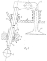
- 1 is a crankcase
- 2 is a rocker arm housing
- 3 is the camshaft of an internal combustion engine.
- the valve 4 of the internal combustion engine is controlled by the camshaft 3 via a rocker arm 5 and a bumper 6.
- the bumper 6 is guided from the camshaft 3 through an opening 8 on the crankcase side and an opening 9 on the rocker arm side through a space 7 (not shown in detail) to the rocker arm 5 and is encased between the crankcase 1 and the rocker arm housing 2 by a protective tube 10.
- the tube end regions of the protective tube 10 can be inserted into the openings 8 and 9 and sealed by means of a round cord or O-ring.
- the round cord ring 11 is arranged according to the invention in a receiving space 12, which is formed together by a groove 13 provided in the protective tube 10 and a groove 14 extending from the opening 8 on the crankcase side.
- the radii R and the width B of the two grooves 13 and 14 are designed in accordance with the usual round ring standard tables, but the groove depth T, which can also be found in the round ring standard tables, is additionally formed by the groove depths T 13 and T 14 of the grooves 13 and 14.
- the protective tube 10 is thus sealed on the one hand and axially secured on the other hand by the round cord ring 11 arranged in the crankcase-side opening 8 in the common receiving space.
- a shoulder 15 is also provided within this opening, which limits the axial movement possibility inward of the crankcase.
- the round cord ring 11 of the tube end of the protective tube 10 which can be inserted into the opening 9 on the rocker arm housing is arranged exclusively in a trapezoidal or rectangular groove 16 on the protective tube side. This groove 16 is formed with the usual dimensions according to the cord ring standard.
- the opening 8 on the crankcase side is provided for inserting the protective tube 10 through a holding element which can be fastened to the crankcase 1, for example by means of screws.
- a shoulder 15 is again provided for one-sided limitation of the possibility of movement on the protective tube side.
- the tube end region of the protective tube 10 which can be inserted into the openings 8 and 9 has an enlarged cross section, so that the protective tube 10 can be guided closer to the bumper 6 between the two tube end regions.
- this exemplary embodiment is designed similarly to the exemplary embodiment according to FIG. 1.
- FIG. 3 shows a greatly enlarged detail corresponding to the detail marking Ili in FIG. 2 of the common receiving space, in order to clarify in particular the dimensions of the two grooves 13 and 14 of the common receiving space 12.
- a round cord ring 11 is cut in its assembled state, ie deformed state, and is shown in dashed lines in its original state with the diameter D R.
- the width B, the radii R and the total groove depth T of the common receiving space 12 can be found in the usual round cord standard tables.
- the total groove depth T of the common receiving space 12 results additively from the groove depth T 13 of the groove 13 of the protective tube 10 and the groove depth T 14 of the groove 14 starting from the opening 8 easy-to-install plug-in connection must be formed, the respective groove depths T 13 and T, 4 and, as a result, the diameter D 14 of the insertion opening 8 and the outer diameter D 13 of the protective tube 10 which can be inserted into the opening 8 are optimized according to the invention.
- the diameter D 14 of the opening 8 is 1.6% to 2.0% smaller than the diameter D T14 of the groove 14 and the maximum outer diameter D 13 of the tube end of the protective tube 10 which can be inserted into the opening 8 is 2% to 3% smaller as the diameter D 14 of the opening 8. This also results in the proportionate groove depths T, 3 and T 14 .
- the radius of the rounded inlet of the groove 14 is formed with a radius R 14 of 0.5 to 1.0 of the diameter D R of the round cord ring 11.
Landscapes
- Engineering & Computer Science (AREA)
- Mechanical Engineering (AREA)
- General Engineering & Computer Science (AREA)
- Valve-Gear Or Valve Arrangements (AREA)
- Multiple-Way Valves (AREA)
Description
- Die Erfindung bezieht sich auf ein Gehäuse für eine Ventilbetätigungsstoßstange einer Brennkraftmaschine mit einem die Ventilbetätigungsstoßstange von einem Kurbelgehäuse zu einem Zylinderkopf, Kipphebelgehäuse oder dergl. ummantelnden Schutzrohr, das jeweils mit einem Rohrende einerseits in eine kurbelgehäuseseitige Öffnung und andererseits in eine zylinderkopf- bzw. kipphebelgehäuseseitige Öffnung einsteckbar und innerhalb der Öffnungen jeweils mittels eines Rundschnurringes abdichtbar ist, der in einer Nut, Ausdrehung oder dergl. angeordnet ist.
- Bei Ventiltrieben von Brennkraftmaschinen mit unten liegender Nockenwelle und insbesondere hängenden Ventilen sind zur Ventilbetätigung u. a. Stoßstangen erforderlich. Da beispielsweise bei luftgekühlten Brennkraftmaschinen die Stoßstangen durch den Kühlluftraum zwischen Kipphebelgehäuse bzw. Zylinderkopf- und Kurbelgehäuse geführt sind, muß der Durchtritt der Stoßstangen durch den Kühlluftraum öldicht abgeschlossen werden, um die Verschmutzung der Kühlrippen mit Lecköl zu vermeiden. Dies geschieht üblicherweise durch ein Stoßstangengehäuse.
- Verschiedenartige Konstruktionen von Stoßstangengehäusen sind aus « Die Konstruktion schnellaufender Verbrennungsmotoren •, Hermann Mettig, Walter De Gryterverlag, Berlin, New York, 1973, Bild 162 auf Seite 244 bekannt. Als drittes Ausführungsbeispiel ist ein gattungsgemäßes Stoßstangengehäuse dargestellt, bei dem die zylinderkopf- und kurbelgehäuseseitigen Verbindungen des Schutzrohres als Steckverbindungen ausgebildet sind, die jeweils mittels eines Rundschnur- bzw. O-Ringes abgedichtet sind. Das kurbelgehäuseseitige Rohrende des Schutzrohres wird durch ein Anschlagelement gebildet, das mit einer Ausdrehung nach Rungschnurringnorm zur Aufnahme eines Rundschnurringes versehen ist und das im montierten Zustand außen am Kurbelgehäuse anliegt. Hierdurch wird eine axiale Bewegungsmöglichkeit des Schutzrohres begrenzt, so daß zum sicheren Halten des Schutzrohres zusätzlich ein Halteelement erforderlich ist, das mit dem Kurbelgehäuse verschraubt ist. Diese Lösung erfordert somit einen erheblichen Fertigungsaufwand in Form von Einzelbauteilen und kann auch hinsichtlich der Montagefreundlichkeit nicht befriedigen, was aber insbesondere bei einer Großserienfertigung von Brennkraftmaschinen von erheblicher Bedeutung ist.
- Aufgabe der vorliegenden Erfindung ist es daher, ein Gehäuse für eine Ventilbetätigungsstoßstange der eingangs genannten Art unter Beibehaltung der als Steckverbindungen ausgebildeten zylinderkopf- und kurbelgehäuseseitigen Verbindungen des Schutzrohres hinsichtlich der für eine sichere dichtende Stoßstangenverkleidung aufzuwendenden Einzelbauteile zu vereinfachen und den aufzubringenden Fertigungsaufwand und die Montage zu minimieren.
- Diese Aufgabe wird erfindungsgemäß dadurch gelöst, daß der Rundschnurring eines Rohrendes des Schutzrohres in einem Aufnahmeraum mit im wesentlichen trapez- bzw. rechteckförmigem Querschnitt angeordnet ist, der gemeinsam durch eine im Schutzrohr vorgesehene Nut und eine von der kurbelgehäuseseitigen oder zylinderkopf- bzw. kipphebelgehäuseseitigen Öffnung ausgehende Nut gebildet wird, wobei die beiden Nuten additiv mit einer Nuttiefe nach Rundschnurringnorm ausgebildet sind.
- Durch diese erfindungsgemäßen Merkmale ist es in vorteilhafter Weise möglich, auf jegliche zusätzlichen Bauteile zur axialen Sicherung des Schutzrohres zu verzichten, da die axiale Sicherung innerhalb des gemeinsamen Aufnahmeraumes des einen Rundschnurringes erfolgt, so daß diesem Aufnahmeraum bzw. diesem Rundschnurring eine doppelte Funktion und somit Bedeutung zukommt. Der gemeinsame Aufnahmeraum ist im wesentlichen den Rundschnurringnormen angepaßt, d. h., daß in Abhängigkeit der zu verwendenden Rundschnurringstärke beispielsweise die Nutenbreite den für Rundschnurringe üblichen genormten Tabellen entnommen werden kann, wobei jedoch die den genormten Tabellen ebenfalls zu entnehmbare Gesamtnutentiefe sich additiv auf beide Nuten des Aufnahmeraumes verteilt. Hierdurch ist eine absolute Dichtheit des Gehäuses sichergestellt. Die Montage des Stoßstangengehäuses ist bei wesentlich geringerem Fertigungsaufwand erheblich vereinfacht, da außer dem Einlegen der Rundschnurringe und dem Einstecken des Schutzrohres keine weiteren Montagearbeiten mehr erforderlich sind. Das erfindungsgemäße Stoßstangengehäuse kann mit den gleichen Vorteilen sowohl bei luftgekühlten als auch bei wassergekühlten Brennkraftmaschinen vorgesehen werden.
- Bevorzugt weist eine Nut des gemeinsamen Aufnahmeraumes einen abgerundeten Einlauf auf, der mit einem Radius von 0,5-1,0 des Durchmessers des zu verwendenden Rundschnurringes ausgebildet ist. Die mit dem abgerundeten Einlauf versehene Nut des gemeinsamen Rundschnurringaufnahmeraumes ist bevorzugt entweder in der kurbelgehäuseseitigen oder der zylinderkopf- bzw. kipphebelgehäuseseitigen Öffnung vorgesehen und die schutzrohrseitige Nut macht bevorzugt 80 % des gesamten Aufnahmeraumes aus, was insbesondere weitere fertigungstechnische Vorteile beinhaltet. Als besonders günstige Gestaltung der mit dem gemeinsamen Aufnahmeraum ausgebildeten Steckverbindung des Schutzrohres hat es sich herausgestellt, wenn der Öffnungsdurchmesser 1,6 % bis 2,05 % kleiner ist als der maximale Durchmesser der von der Öffnung ausgehenden Nut und wenn der maximale Durchmesser des in diese Öffnung einsteckbaren Rohrendes 2 % bis 3 % geringer ist als der entsprechende Durchmesser der kurbelgehäuseseitigen oder zylinderkopf- bzw. kipphebelgehäuseseitigen Öffnung. Durch diese erfindungsgemäße Gestaltung der Steckverbindung des Ventilbetätigungstoßstangengehäuses ist es in vorteilhafter Weise möglich, der doppelten Funktion des Aufnahmeraumes hinsichtlich Abdichtung und axialer Sicherung des Schutzrohres bei guter Montagemöglichkeit optimal Rechnung zu tragen.
- Weitere vorteilhafte Ausgestaltungen und Weiterbildungen der Erfindung sind in den Unteransprüchen angegeben.
- Zur weiteren Erläuterung der Erfindung wird auf die Zeichnungen verwiesen, in denen jeweils Ausführungsbeispiele der Erfindung dargestellt sind.
- Es zeigen :
- Figur 1 eine schematische Querschnittsdarstellung eines Ausführungsbeispieles eines erfindungsgemäß gestalteten Ventilbetätigungsstoßstangengehäuses ;
- Figur 2 ein weiteres Ausführungsbeispiel eines erfindungsgemäß gestalteten Ventilbetätigungsstoßstangengehäuses ;
- Figur 3 einen vergrößerten Teilausschnitt nach Detail 111 in Fig. 2 in einer Querschnittsdarstellung.
- In den Fig. 1 bis 3 sind grundsätzlich gleichwirkende Teile mit gleichen Bezugsziffern versehen, wobei nur die zum Verständnis der Erfindung notwendigen Teile im Einzelnen näher dargestellt sind. Mit 1 ist ein Kurbelgehäuse, mit 2 ein Kipphebelgehäuse und mit 3 die Nockenwelle einer Brennkraftmaschine bezeichnet. Das Ventil 4 der Brennkraftmaschine wird über einen Kipphebel 5 und eine Stoßstange 6 von der Nockenwelle 3 gesteuert. Die Stoßstange 6 ist von der Nockenwelle 3 durch eine kurbelgehäuseseitige Öffnung 8 und eine kipphebelgehäuseseitige Öffnung 9 durch einen nicht im Einzelnen dargestellten Raum 7 zum Kipphebel 5 geführt und wird zwischen dem Kurbelgehäuse 1 und dem Kipphebelgehäuse 2 von einem Schutzrohr 10 ummantelt. Die Rohrendbereiche des Schutzrohres 10 sind in die Öffnungen 8 und 9 einsteckbar und mittels eines Rundschnur- bzw. O-Ringes abgedichtet. In der kurbelgehäuseseitigen Offnung 8 ist erfindungsgemäß der Rundschnurring 11 in einem Aufnahmeraum 12 angeordnet, der gemeinsam durch eine in dem Schutzrohr 10 vorgesehene Nut 13 und eine von der kurbelgehäuseseitigen Öffnung 8 ausgehende Nut 14 gebildet wird. Die Radien R und die Breite B der beiden Nuten 13 und 14 sind dabei entsprechend der üblichen Rundschnurringnormtabellen ausgebildet, wobei jedoch die ebenfalls den Rundschnurringnormtabellen entnehmbare Nuttiefe T additiv durch die Nuttiefen T13 und T14 der Nuten 13 und 14 gebildet werden. Durch den in der kurbelgehäuseseitigen Öffnung 8 in dem gemeinsamen Aufnahmeraum angeordneten Rundschnurring 11 ist somit das Schutzrohr 10 einerseits abgedichtet und andererseits axial gesichert. Zusätzlich zur axialen Sicherung ist innerhalb dieser Öffnung noch ein Absatz 15 vorgesehen, der die axiale Bewegungsmöglichkeit kurbelgehäuseeinwärts begrenzt. Der Rundschnurring 11 des in die kipphebelgehäuseseitige Öffnung 9 einsteckbaren Rohrendes des Schutzrohres 10 ist ausschließlich in einer schutzrohrseitigen trapez- bzw. rechteckförmigen Nut 16 angeordnet. Diese Nut 16 ist mit den üblichen Abmessungen nach Rundschnurringnorm ausgebildet.
- In dem Ausführungsbeispiel nach Fig. 2 ist die kurbelgehäuseseitige Öffnung 8 zum Einstecken des Schutzrohres 10 durch ein am Kurbelgehäuse 1 beispielsweise mittels Schrauben befestigbares Halteelement vorgesehen. Innerhalb des Halteelements 17 ist wiederum ein Absatz 15 vorgesehen zur einseitigen Begrenzung der schutzrohrseitigen Bewegungsmöglichkeit. Weiterhin weist in diesem Ausführungsbeispiel der in die Öffnungen 8 und 9 einsteckbare Rohrendbereich des Schutzrohres 10 einen erweiteren Querschnitt auf, so daß zwischen den beiden Rohrendbereichen das Schutzrohr 10 enger an der Stoßstange 6 geführt sein kann. Ansonsten ist dieses Ausführungsbeispiel ähnlich gestaltet wie das Ausführungsbeispiel nach Fig. 1.
- In Fig. 3 ist ein stark vergrößerter Ausschnitt entsprechend der Detailmarkierung Ili in Fig. 2 des gemeinsamen Aufnahmeraumes dargestellt, um insbesondere die Abmessungen der beiden Nuten 13 und 14 des gemeinsamen Aufnahmeraumes 12 zu verdeutlichen. Hier ist ein Rundschnurring 11 in seinem montierten Zustand, d. h. verformten Zustand geschnitten und strichpunktiert in seinem Ursprungszustand mit dem Durchmesser DR dargestellt. In Abhängigkeit des Rundschnurringdurchmessers DR kann den üblichen Rundschnurringnormtabellen die Breite B, die Radien R und die Gesamtnuttiefe T des gemeinsamen Aufnahmeraumes 12 entnommen werden. Die Gesamtnuttiefe T des gemeinsamen Aufnahmeraumes 12 ergibt sich additiv aus der Nuttiefe T13 der Nut 13 des Schutzrohres 10 und der Nuttiefe T14 der von der Öffnung 8 ausgehenden Nut 14. Da für eine optimale Abdichtung der Gesamtnuttiefe T vorgegeben ist aber dennoch die Verbindung als gut montierbare Steckverbindung ausgebildet sein muß, sind die jeweiligen Nuttiefen T13 und T,4 und daraus resultierend die Durchmesser D14 der Einstecköffnung 8 und der äußere Durchmesser D13 des in die Öffnung 8 einsteckbaren Schutzrohres 10 erfindungsgemäß optimiert. Der Durchmesser D14 der Öffnung 8 ist 1,6 % bis 2,0 % kleiner als der Durchmesser DT14 der Nut 14 und der maximale äußere Durchmesser D13 des in die Öffnung 8 einsteckbaren Rohrendes des Schutzrohres 10 ist 2 % bis 3 % geringer als der Durchmesser D14 der Öffnung 8. Hieraus ergeben sich auch gleichzeitig die anteiligen Nuttiefen T,3 und T14. Der Radius des abgerundeten Einlaufes der Nut 14 ist mit einem Radius R14 von 0,5 bis 1,0 des Durchmessers DR des Rundschnurringes 11 ausgebildet.
Claims (10)
Priority Applications (1)
| Application Number | Priority Date | Filing Date | Title |
|---|---|---|---|
| AT84102086T ATE25127T1 (de) | 1983-04-22 | 1984-02-29 | Gehaeuse fuer eine ventilbetaetigungsstossstange. |
Applications Claiming Priority (2)
| Application Number | Priority Date | Filing Date | Title |
|---|---|---|---|
| DE19833314721 DE3314721A1 (de) | 1983-04-22 | 1983-04-22 | Gehaeuse fuer eine ventilbetaetigungsstossstange |
| DE3314721 | 1983-04-22 |
Publications (3)
| Publication Number | Publication Date |
|---|---|
| EP0123063A2 EP0123063A2 (de) | 1984-10-31 |
| EP0123063A3 EP0123063A3 (en) | 1985-09-25 |
| EP0123063B1 true EP0123063B1 (de) | 1987-01-21 |
Family
ID=6197144
Family Applications (1)
| Application Number | Title | Priority Date | Filing Date |
|---|---|---|---|
| EP84102086A Expired EP0123063B1 (de) | 1983-04-22 | 1984-02-29 | Gehäuse für eine Ventilbetätigungsstossstange |
Country Status (4)
| Country | Link |
|---|---|
| EP (1) | EP0123063B1 (de) |
| AT (1) | ATE25127T1 (de) |
| CA (1) | CA1255607A (de) |
| DE (2) | DE3314721A1 (de) |
Families Citing this family (5)
| Publication number | Priority date | Publication date | Assignee | Title |
|---|---|---|---|---|
| DE4142811C2 (de) * | 1990-12-26 | 1999-07-22 | Ryobi Ltd | Schmiervorrichtung einer 4-Takt-Brennkraftmaschineneinheit |
| US5347967A (en) * | 1993-06-25 | 1994-09-20 | Mcculloch Corporation | Four-stroke internal combustion engine |
| JP2003021010A (ja) | 2001-07-06 | 2003-01-24 | Shin Daiwa Kogyo Co Ltd | 小型エンジンにおけるエアクリーナー |
| JP2003056313A (ja) | 2001-08-10 | 2003-02-26 | Shin Daiwa Kogyo Co Ltd | エンジン |
| US6883485B2 (en) * | 2001-12-07 | 2005-04-26 | Honda Giken Kogyo Kabushiki Kaisha | OHV and gear mechanism for engine |
Family Cites Families (6)
| Publication number | Priority date | Publication date | Assignee | Title |
|---|---|---|---|---|
| DE915166C (de) * | 1943-08-03 | 1954-07-15 | Perrot Regnerbau G M B H | Verbindungsstueck zwischen duennwandigem Rohr und Gewindefittings |
| US2432592A (en) * | 1943-10-25 | 1947-12-16 | Weatherhead Co | Tubular connection |
| US2657679A (en) * | 1951-09-08 | 1953-11-03 | Continental Motors Corp | Push rod housing structure |
| DE1895895U (de) * | 1961-09-30 | 1964-07-02 | Porsche Kg | Ventilsteuerung fuer brennkraftmaschinen. |
| US4066281A (en) * | 1976-07-16 | 1978-01-03 | Bonis John C De | Porsche automobile oil drain replacement tube |
| SE444358B (sv) * | 1981-04-23 | 1986-04-07 | Finnveden Dev Ltd Ab | Sett for avtetning av spalten mellan tva tetningsytor samt tetningsanordning for genomforande av settet |
-
1983
- 1983-04-22 DE DE19833314721 patent/DE3314721A1/de not_active Withdrawn
-
1984
- 1984-02-29 DE DE8484102086T patent/DE3462170D1/de not_active Expired
- 1984-02-29 EP EP84102086A patent/EP0123063B1/de not_active Expired
- 1984-02-29 AT AT84102086T patent/ATE25127T1/de not_active IP Right Cessation
- 1984-04-19 CA CA000452379A patent/CA1255607A/en not_active Expired
Also Published As
| Publication number | Publication date |
|---|---|
| ATE25127T1 (de) | 1987-02-15 |
| EP0123063A2 (de) | 1984-10-31 |
| DE3462170D1 (en) | 1987-02-26 |
| EP0123063A3 (en) | 1985-09-25 |
| DE3314721A1 (de) | 1984-10-25 |
| CA1255607A (en) | 1989-06-13 |
Similar Documents
| Publication | Publication Date | Title |
|---|---|---|
| DE69325669T2 (de) | Linearmotor für ein ventil | |
| EP0342451A2 (de) | Verriegelung für eine fluidische Steckverbindung zwischen einer Fluidleitung und einem Anschlussteil | |
| EP0610543B1 (de) | Befestigungssystem | |
| DE4328709C2 (de) | Elektromagnetventil | |
| DE102015203378A1 (de) | Verbrennungskraftmaschine mit einstellbarem variablen Verdichtungsverhältnis und einem Schaltmodul | |
| DE69008710T2 (de) | Ventil mit ausbaubarem Einsatzstück. | |
| DE3444550A1 (de) | Zahnstangen-lenkgetriebe fuer ein fahrzeug | |
| DE19916675B4 (de) | Vorrichtung zur relativen Winkelverstellung einer Nockenwelle | |
| EP0123063A2 (de) | Gehäuse für eine Ventilbetätigungsstossstange | |
| DE2525431A1 (de) | Abdichtung zwischen verhaeltnismaessig rotierbaren elementen | |
| DE4129638A1 (de) | Hydraulisches sitzventil | |
| DE8817020U1 (de) | Lösbare Schnell-Steckverbindung | |
| DE69008266T2 (de) | Elektromagnetisches Ventil. | |
| DE19958629B4 (de) | Vorrichtung zum Verändern der Steuerzeiten einer Brennkraftmaschine | |
| DE3409236A1 (de) | Aeusseres fuehrungsteil fuer einen ventilstoessel | |
| WO2011128191A1 (de) | Anordnung eines ventils in einer bohrung eines kanalgehäuses | |
| DE2726503A1 (de) | Steuerschieber fuer ein hydraulisches wegeventil | |
| EP0814308B1 (de) | Heizkörper | |
| DE102015205770A1 (de) | Nockenwellenbaugruppe | |
| DE3625058A1 (de) | Ventil | |
| DE19832627B4 (de) | Vorrichtung zum Einblasen von Sekundärluft in den Abgasbereich einer Brennkraftmaschine | |
| EP0744531A1 (de) | Zylinderkopf für eine Brennkraftmaschine | |
| DE4011111C1 (en) | Panel radiator connection - has feed and return connections joined to connection piece linking two radiator panels and screwed in place | |
| DE2327535A1 (de) | Servolenkung fuer kraftfahrzeuge | |
| DE4125815C2 (de) | Ventil, insbes. pneumatisches Schalt-, Stetig-, Vorsteuerventil u. dgl. |
Legal Events
| Date | Code | Title | Description |
|---|---|---|---|
| PUAI | Public reference made under article 153(3) epc to a published international application that has entered the european phase |
Free format text: ORIGINAL CODE: 0009012 |
|
| AK | Designated contracting states |
Designated state(s): AT DE FR IT |
|
| PUAL | Search report despatched |
Free format text: ORIGINAL CODE: 0009013 |
|
| AK | Designated contracting states |
Designated state(s): AT DE FR IT |
|
| 17P | Request for examination filed |
Effective date: 19850808 |
|
| 17Q | First examination report despatched |
Effective date: 19860411 |
|
| GRAA | (expected) grant |
Free format text: ORIGINAL CODE: 0009210 |
|
| AK | Designated contracting states |
Kind code of ref document: B1 Designated state(s): AT DE FR IT |
|
| REF | Corresponds to: |
Ref document number: 25127 Country of ref document: AT Date of ref document: 19870215 Kind code of ref document: T |
|
| ITF | It: translation for a ep patent filed | ||
| REF | Corresponds to: |
Ref document number: 3462170 Country of ref document: DE Date of ref document: 19870226 |
|
| ET | Fr: translation filed | ||
| PLBE | No opposition filed within time limit |
Free format text: ORIGINAL CODE: 0009261 |
|
| STAA | Information on the status of an ep patent application or granted ep patent |
Free format text: STATUS: NO OPPOSITION FILED WITHIN TIME LIMIT |
|
| 26N | No opposition filed | ||
| PGFP | Annual fee paid to national office [announced via postgrant information from national office to epo] |
Ref country code: AT Payment date: 19890110 Year of fee payment: 6 |
|
| PGFP | Annual fee paid to national office [announced via postgrant information from national office to epo] |
Ref country code: FR Payment date: 19890111 Year of fee payment: 6 |
|
| ITTA | It: last paid annual fee | ||
| REG | Reference to a national code |
Ref country code: GB Ref legal event code: 746 |
|
| PG25 | Lapsed in a contracting state [announced via postgrant information from national office to epo] |
Ref country code: AT Effective date: 19900228 |
|
| PG25 | Lapsed in a contracting state [announced via postgrant information from national office to epo] |
Ref country code: FR Effective date: 19901031 |
|
| REG | Reference to a national code |
Ref country code: FR Ref legal event code: ST |
|
| PGFP | Annual fee paid to national office [announced via postgrant information from national office to epo] |
Ref country code: DE Payment date: 19910117 Year of fee payment: 8 |
|
| PG25 | Lapsed in a contracting state [announced via postgrant information from national office to epo] |
Ref country code: DE Effective date: 19921103 |