EP0118955A2 - Hochleistungs-Röntgenstrahlenquelle mit Anodenkühlung - Google Patents
Hochleistungs-Röntgenstrahlenquelle mit Anodenkühlung Download PDFInfo
- Publication number
- EP0118955A2 EP0118955A2 EP84200319A EP84200319A EP0118955A2 EP 0118955 A2 EP0118955 A2 EP 0118955A2 EP 84200319 A EP84200319 A EP 84200319A EP 84200319 A EP84200319 A EP 84200319A EP 0118955 A2 EP0118955 A2 EP 0118955A2
- Authority
- EP
- European Patent Office
- Prior art keywords
- extension
- target
- anode
- truncated
- hollow
- Prior art date
- Legal status (The legal status is an assumption and is not a legal conclusion. Google has not performed a legal analysis and makes no representation as to the accuracy of the status listed.)
- Ceased
Links
Images
Classifications
-
- H—ELECTRICITY
- H01—ELECTRIC ELEMENTS
- H01J—ELECTRIC DISCHARGE TUBES OR DISCHARGE LAMPS
- H01J35/00—X-ray tubes
- H01J35/02—Details
- H01J35/04—Electrodes ; Mutual position thereof; Constructional adaptations therefor
- H01J35/08—Anodes; Anti cathodes
- H01J35/10—Rotary anodes; Arrangements for rotating anodes; Cooling rotary anodes
- H01J35/105—Cooling of rotating anodes, e.g. heat emitting layers or structures
- H01J35/106—Active cooling, e.g. fluid flow, heat pipes
Definitions
- This invention relates to the generation of x-rays particularly useful in x-ray lithographic systems to obtain a uniform x-ray flux emanating from a small spot. Such systems may be used in the fabrication of wafers for large scale integrated circuit production.
- the invention may also be utilized in x-ray sources for medical radiographic x-ray, diffraction study and tomographic applications. More particularly, it relates to means to more effectively cool the target anode and to prevent burn-out of the conical tip of prior art anodes.
- X-rays are utilized in various fields including medical imaging and x-ray lithographic systems for fabricating large scale integration (LSI) semiconductor devices.
- the X-rays are formed by an annular-shaped electron gun, various shield and extraction grids and beam focusing devices to effect transmission of a hollow high-energy (about 10-30 keV, typically 25 keV) electron beam on an inverted conical-shaped target.
- the vast majority, i.e. 99-99.9% of the energy in the beam of electrons bombarding the target, is converted to heat energy but most of the remaining energy produce x-rays which exit through an x-ray transmissive window (typically beryllium for lithography applications) which is part of the enclosure of the overall vacuum system.
- an x-ray transmissive window typically beryllium for lithography applications
- Cooling of the target anode is effected by providing a water diverter to provide high water velocity on the back side of the inverted conical anode target so as to establish high velocity turbulent flow resulting in nucleate boiling. This avoids laminar flow or vapor layers forming on that cone back surface.
- the authors of the Journal Vacuum Science Technology article who include the inventors of the cited improvement patents caution to avoid heating the apex of the cone with the electron beam because to do so will burn out the tip of the cone, since the apex of the cone is not efficiently cooled.
- high speed coolant normally water
- structure and methods are provided for obtaining the greatest output of X-rays from a conical anode target of the type where the electron beam impinging on the target is substantially nonparallel or substantially parallel to the axis of rotation of the cone without damaging the anode target which must withstand and dissipate the large flux of heat resulting from electrons impinging on its surface.
- the present invention provides structure which decreases and even eliminates the density of the impinging charged particles in the apex region of the anode target thereby to prevent tip "burn-out".
- the tip of the conical target is extended beyond the inverted conical impingement surface of the target anode.
- the extension provides additional material mass and area to reduce the heat energy generated per unit area by the impinging beam of charged particles and shields the tip or apex of the target from this beam thereby preventing hot spot formation and thus "burn-out" at the tip.
- the inward extension of the target is of generally cylindrical configuration, in one embodiment, so that it not only shields the tip but also provides an inner surface of an annular flow area so that coolant flowing in this annulus between both the extension and a surrounding conduit and the downstream main conical anode target surfaces and the surrounding conduit, has a greater surface area from which to remove heat than in the prior art.
- Such construction enables the X-ray generator to be reliably operated at high beam densities for long periods.
- the cylindrical extension of the anode cone is cut by a substantially flat plane oriented at an angle to the longitudinal axis of the cylinder thereby to provide an ellipsoidal line of intersection of the cylinder through the flat plane.
- the flat plane is angled relative to the longitudinal axis of the cylinder, incident electrons entering in a direction parallel to the axis of rotation of the anode cone which in the prior art would strike the apex of the target anode now strike the flat surface of the extension of the anode.
- the incident energy per unit area of the flat portion of the extension can be controlled by carefully selecting the proper angle for this flat section with respect to the angle of incidence of the electrons.
- the rearward extension of the target constitutes substantially a continuaton of at least one of the two surfaces of the V-groove rearwardly at a reduced angle with regard to the plane of symmetry.
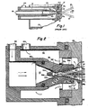
- a prior art device generally similar to that shown in U.S. patent 4,238,682 is shown in Figure 1.
- a conical target anode 14 is mounted in a facing plate 17 of the anode portion of the overall X-ray source system.
- the term "conical” as used herein includes converging surfaces such a those surfaces of revolution which are conical or are substantially conical such as a hyperbola formed by a vertical section of a right circular cone. It also includes a V-shaped peripheral notch in a cylindrical rotating anode, and the "axis of revolution" of the conical target is substituted for by the symmetry plane of the V-shaped groove of a rotating anode.
- the "tip" or "apex” of the conical target includes surfaces adjacent to the point where the axis of revolution meets the inner cone surface or, in the alternate embodiment, the points where the symmetry plane of the V-shaped groove meets the inner V-groove surface.
- Cathode structure for generating the high energy electron beam is omitted from the drawing but is shown in United States Patents No. 4,238,682 and No. 4,258,262, the disclosures of which are herein incorporated by reference.
- the designation "electron beam” is used to mean any beam of charged particles used to generate X-rays.
- the electron beams 15, 16 exit the cathode in the form of a hollow ring of electrons which bombard the inner surface 14a of the inverted conical anode 14 to cause the emission of x-rays 25 from the anode surface 14a.
- These beams are schematically shown as sets of beams 15 and 16 focused by suitable well-known focusing means at the cathode (not shown) to strike the inner surface 14a of anode 14. Care is taken to avoid having any part of the beams 15 and 16 strike the apex 14b of anode 14 which would cause burn-out, of or even the formation of an actual hole in the apex 14b by reason of the heat generated by electrons impinging at the apex.
- the design of the prior art anode results in an inability to cool adequately the apex 14b with the cooling system.
- Anode rim 14c is mounted in faceplate 17 by brazing. Rim 14c is at the wide diameter base of the anode inverted cone. Since the anode structure is cylindrical and the beams emitted from the cathode are circular, the cross-sectional view in each of the Figures 1-4 is a symmetrical one.
- a coolant inlet source 18 is provided along with a coolant inlet passageway 19 for conducting a specially-treated deionized water coolant through a cylindrical conduit 20 into an annular flow passage 21 formed between that portion of the inner surface of conduit 20 surrounding anode 14 and the outer surface 14d (i.e., the surface opposite impingement surface 14a) of the conical anode 14. Coolant is pumped through the annulus 21 effecting cooling typically by nucleate boiling. The coolant exits through coolant outlet chamber 22 and passes rearwardly through coolant exit passageway 23 to outlet 24.
- the beam-forming electrodes as shown in patent 4,258,262 malfunction in any way and the beam varies in its direction, the beam is capable of impinging on the apex area 14b where the heat flux cannot be adequately removed by the coolant system. This then can cause catastrophic damage and burn-out of the apex 14b of the target anode 14.
- FIG 2 shows the preferred embodiment of applicant's invention wherein an improved anode target 3 4 is provided.
- Anode target 34 comprises a conical target with an inner surface of revolution 34a onto which the bombarding electrons impinge.
- the conical target anode is truncated at 34e and a cylindrical extension 34b is connected thereat to extend the apex 34e of the target 3 4 upstream or inward towards the cooling source.
- the target is secured in place by an anode target base or rim 34c which is fastened into an anode system front closure plate 42.
- Front closure plate 42 has a circular aperture 32 through which the electron beams 33 pass into the inverted cone.
- X-rays resultant from the bombardment exit from the target through aperture 42 as shown by the axial arrow and are subsequently directed as shown for example in Fig. 1 of U.S. Patent 4,258,262.
- Extending further upstream from the cylindrical hollow extension 34b and defining the shape of apex 34e is a bullet-shaped diverter section or end piece 34d which extends into the flow of coolant. End piece 34d diverts the coolant flow into annulus 60 surrounding the cylindrical extension 34b and into the annulus 39 between the principal anode target area 34a and conduit 36.
- apex 14b of the prior art device is shown in dotted lines to illustrate the position of the extension 34b and apex 34e in accordance with this invention rearwarc of the hypothetical apex 14b of truncated cone section 34a.
- Apex 14b is not actually present in either of the Figure 2 or 3 embodiments.
- a coolant source inlet 35 and inlet passage 35a are provided upstream of conduit 36.
- a conduit entrance 37 conducts cooling fluid into the region of the diverter end piece 34d.
- the cooling medium such as deionized water, is conducted through annular flow passage 60 between the walls of the inner surface of conduit 3'6 and the outer surface of cylindrical extension 34b and further downstream between the conduit 36 and the anode wall section 34a.
- the conduit 36 has a portion shown by the dashed line 38 removed therefrom in order to provide a suitable entrance annulus for coolant fluid to the downstream passageway 39.
- coolant medium i.e., fluid in a turbulent state passes through coolant passageway 39 between the conduit 36 and anode 34 where it cools the anode for example, by nucleate boiling, and then into coolant exit chamber 40.
- the heated water then exits through coolant exit passage 41 and a coolant exit passageway 43 to a coolant exit outlet 44.
- the flow of coolant is shown by the arrows in Figure 2. It is contemplated that flow of coolant may be in the opposite direction. In such event the coolant flow rates and the flow passages would be modified to optimize the heat transfer from the cone and extension..surfaces.
- the nature of the cooling of the target required is apparent when one realizes that the electrons typically have an energy of from 10-30 keV and that most of the energy of the electrons impinging upon the target becomes heat with the remainder becoming X-rays.
- the electrons scatter in the target material and x-rays are generated as a result.
- the soft x-rays typically have a wavelength about two hundredths to two thousandths of that of light, i.e., 2-20 Angstroms.
- the electrons penetrate a few microns at most into the surface of the target material, so most of the heat in the target is generated within a few microns of the inner surface of the target. This heat must be transferred to the outer or "cool side" of the target.
- deionized water is used to remove the heat from the target.
- sufficient energy is generated by the target that the water used to cool the target normally boils as it passes the target. The boiling of the water avoids the formation of a laminate layer and increases, the efficiency with which heat can be removed from the target.
- the cylindrical extension 34b of this invention decreases the electron density impinging upon the target material in the region of the cylindrical extension. However, generally it is desirable that the electrons hit only the side of the conical portion of the target and not the sides of the cylindrical extension. As will be shown shortly, the energy generated per unit area of the cylindrical extension can also be reduced by making the cylindrical extension of greater diameter.
- the slopes 39a and 39b of the conduit 36 and the surface of revolution 34a vary so that the annulus 39 becomes narrower as it progresses downstream towards the target base 34c. Maintenance of substantially constant cross-sectional area across the annulus 39 is provided by the narrowing of the conduit.
- extension 34b extends rearwardly toward the upstream coolant flow and away from base 34c such that the hollow cylindrical extension 34b is outside the impingement areas of the normal operating beams exiting from the cathode and impinging the region of surface 34a.
- the extension 34b is adequately cooled by the high speed passage of coolant through the annulus 60 and the mass and area of end piece 34d is sufficient to act as a heat sink such that any stray or variable beams of electrons, such as any striking inwardly of beams 33a and 33b, which might, due to malfunction or other cause, impinge in the upstream area of the cylindrical extension will not puncture or otherwise destroy or burn-out the upstream tip end of the anode target.
- the conical portion may be of a different material which has the desired x-ray radiation, such as palladium.
- the cylindrical extension 34b effectively shields the top or apex 34e from the incident electrons and thus prevents tip burn-out.
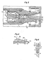
- Figure 3 is a modification of the improved anode target of this invention.
- the extension 34c to the anode target 64 in Figure 3 comprises a conical bridging member 64b integrally attached to the truncated end 64f of the region 64a of target 64 on which electrons impinge.
- a cylindrical section 64c is connected to the other end of member 64b.
- a solid root portion 64d connects the cylindrical section 64c to a cylindrical end 64e into which a diverter connector 46 extending from the front surface of diverter 45 is inserted.
- the bullet-shaped nose 47 of the diverter 45 extends in juxtaposed spaced position slightly beyond the front edge 49 of the cylindrical conduit 58.
- Diverter 45 may be cantilevered into the coolant stream as shown or may be supported by a spider of radial arm(s) extending between the diverter and-member 58.
- Cooling medium or fluid passes through inwardly inclined entrance 55 to a cylindrical passageway 56 and a tapered entrance section 57 to the annulus entrance 51.
- An annulus 52a extends between the target cylindrical extension 64c and the inner peripheral surface of conduit 58 and a connected downstream tapered annular passageway 52b extends between the outer surfaces of impingement area 64a of the target anode 64 and a forward-extending tail piece 59 of conduit 58.
- Cooling fluid flows in the direction shown by the arrows and, after cooling the anode target, the cooling fluid is conducted through coolant exit chamber 53 rearwardly through coolant exit passageway 54 to an exit (not shown).
- the electron beam array is permitted to pass through the former apex position 14b internally of extension section 64c where it can impinge as illustrated by beam ray 61.
- extension 64c At this position, there is sufficient exterior cooling of extension 64c to prevent any damage to the anode target and direct impingement of the electrons 61 on the tip or apex 64g of the target 64 is prevented by cylindrical extension 64c.
- the various extensions and/or diverters in the various embodiments may have exterior surfaces which are textured or roughened to increase turbulence and heat transfer or may include longitudinally-extending fins to present more surface area to the cooling medium.
- Figure 4 is a partial view showing the narrowing of the passageway 52b (Figure 3) by providing varied slopes on the inner peripheral surface of conduit 36 ( Figure 2) or conduit 58 ( Figure 3) and on the outer cool side surface 39b of the anode target.
- the slope of the surface 39a on conduit 36 will be 11° and the slope of surface 39b would be 12.5°. This provides a continually narrowing passageway or annulus as coolant progresses from station 3-3 to station 2-2 along the cool-side surface of the anode target.
- FIG 5 illustrates another embodiment of this invention wherein the cylindrical extension of the target anode of this invention such as shown in Figure 3 or in Figure 2 is angularly truncated by a flat wall 81.
- the remaining cylindrical portion 83 is parallel to the longitudinal axis of the cylinder of the extension.
- the inner surface of flat wall 81 is arranged to intercept those incident substantially parallel-to-the-axis electrons 86 which would normally have hit the apex or tip of the prior art target anode but which now pass through opening 87 created by the removal of the tip (such as tip 14b as illustrated in Figure 3).
- a portion of the electrons 86 denoted by those electrons circled 86a in Figure 5 strike the flat angular truncation of cylinder 83.
- Channel 84a is provided directly adjacent the outer surface of flat truncated wall 81 and is adapted for the passage of a fluid under pressure for the removal of heat from material 81.
- Channel 84a is substantially planar in the regions adjacent wall 81 but is cylindrical (i.e., a curved annulus) adjacent the other portions of cylindrical wall surface 83.
- channel 84b is formed between the outer surface of cylindrical portions of the extension 92 and the inner surface of diverter 85b.
- the channel thickness t 1 between these two surfaces must be controlled in such a way so as to insure that the fluid flow through flat channel 84a adjacent the flat wall surface upon which the electron beam 86a strikes is adequate to provide sufficient cooling capacity to cool the wall 81 and prevent burnout of the extension 92 of. the tip.
- the thickness t 2 of substantial flat channel 84a between the outer surface of flat wall 81 and a flat inner surface 88 of diverter portion 85a generally coincident to wall 81 must be properly dimensioned along with thickness t l to insure the proper fluid flow through the channels 84a and 84b.
- Channels 84a and 84b merge at the longitudinal edges of the truncation.
- Diverter position 85a may be a flat faced insert provided in the overall diverter structure.
- Channel 52b ( Figure 4) has a channel width of about 15 mils (0.015 inches) at section 3-3 at the beginning of channel 52b and a thickness of 10 mils at section 2-2 near the exit from this channel. Three gallons of deionized water per minute were pumped through this annular channel during the operation of the target anode of the type shown in Figure 2 with the incident energy being approximately 7.5 kilowatts.
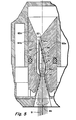
- FIG. 6 shows a rotating cylindrical anode 70 having a V-groove kerf in its outer periphery forming two inwardly converging surfaces 71, 72.
- a rearward hollow extension 74 is provided resulting in a beam-facing expanse of surface which can transfer the heat generated by stray or desired infringing beams.
- anode is rotated by suitable means (not shown) connected-to a central shaft 76 which is connected to the anode.
- Anode 70 while shown with solid material cooling means 75 may contain passageways for the flow of liquid or slurry coolants.
- the conical or rotating anode may be made of various metals or composite materials which emit x-rays. These include Al, Cu, Si, Pd, W, Mo or a rhenium-tungsten alloy.
- An insert of the target material may be brazed, sputtered or evaporated on the conical surface of either the fixed conical anode or the rotating anode.
Landscapes
- Physics & Mathematics (AREA)
- Fluid Mechanics (AREA)
- X-Ray Techniques (AREA)
- Exposure And Positioning Against Photoresist Photosensitive Materials (AREA)
- Exposure Of Semiconductors, Excluding Electron Or Ion Beam Exposure (AREA)
Applications Claiming Priority (2)
| Application Number | Priority Date | Filing Date | Title |
|---|---|---|---|
| US06/473,483 US4521903A (en) | 1983-03-09 | 1983-03-09 | High power x-ray source with improved anode cooling |
| US473483 | 1990-02-01 |
Publications (2)
| Publication Number | Publication Date |
|---|---|
| EP0118955A2 true EP0118955A2 (de) | 1984-09-19 |
| EP0118955A3 EP0118955A3 (de) | 1986-01-15 |
Family
ID=23879716
Family Applications (1)
| Application Number | Title | Priority Date | Filing Date |
|---|---|---|---|
| EP84200319A Ceased EP0118955A3 (de) | 1983-03-09 | 1984-03-07 | Hochleistungs-Röntgenstrahlenquelle mit Anodenkühlung |
Country Status (3)
| Country | Link |
|---|---|
| US (1) | US4521903A (de) |
| EP (1) | EP0118955A3 (de) |
| JP (1) | JPS59205139A (de) |
Cited By (2)
| Publication number | Priority date | Publication date | Assignee | Title |
|---|---|---|---|---|
| WO1986001938A1 (en) * | 1984-09-07 | 1986-03-27 | American Telephone & Telegraph Company | X-ray source |
| EP0212548A3 (en) * | 1985-08-12 | 1988-06-08 | Fujitsu Limited | A rotary anode assembly for an x-ray source |
Families Citing this family (16)
| Publication number | Priority date | Publication date | Assignee | Title |
|---|---|---|---|---|
| FR2534066B1 (fr) * | 1982-10-05 | 1989-09-08 | Thomson Csf | Tube a rayons x produisant un faisceau a haut rendement, notamment en forme de pinceau |
| US4873709A (en) * | 1987-07-24 | 1989-10-10 | Meitec Corporation | X-ray generator with grooved rotary anode |
| JPH0640475B2 (ja) * | 1988-01-25 | 1994-05-25 | 日本電子株式会社 | 電界放出型電子銃 |
| WO2004023852A2 (en) * | 2002-09-03 | 2004-03-18 | Parker Medical, Inc. | Multiple grooved x-ray generator |
| US7197116B2 (en) * | 2004-11-16 | 2007-03-27 | General Electric Company | Wide scanning x-ray source |
| US20080239262A1 (en) * | 2007-03-29 | 2008-10-02 | Asml Netherlands B.V. | Radiation source for generating electromagnetic radiation and method for generating electromagnetic radiation |
| CN101848624B (zh) * | 2009-03-25 | 2013-07-03 | 富准精密工业(深圳)有限公司 | 液冷散热装置 |
| DE102010030713B4 (de) * | 2010-02-17 | 2018-05-03 | rtw RÖNTGEN-TECHNIK DR. WARRIKHOFF GmbH & Co. KG | Röntgenquelle zur Erzeugung von Röntgenstrahlen mit einem Hohlkörpertarget und ein Verfahren zur Erzeugung von Röntgenstrahlung in einem Hohlkörpertarget |
| AT12862U1 (de) * | 2011-08-05 | 2013-01-15 | Plansee Se | Anode mit linearer haupterstreckungsrichtung |
| CA2911525A1 (en) | 2013-05-17 | 2014-11-20 | Martin A. Stuart | Dielectric wall accelerator utilizing diamond or diamond like carbon |
| US9508523B2 (en) * | 2014-03-15 | 2016-11-29 | Stellarray, Inc. | Forward flux channel X-ray source |
| DE102017217181B3 (de) * | 2017-09-27 | 2018-10-11 | Siemens Healthcare Gmbh | Stehanode für einen Röntgenstrahler und Röntgenstrahler |
| US11011341B2 (en) * | 2018-05-21 | 2021-05-18 | Varex Imaging Corporation | Transmission target for a high power electron beam |
| CN110400650B (zh) * | 2019-08-06 | 2025-03-14 | 中国原子能科学研究院 | 转换靶装置及靶材料层结构 |
| JP7276865B2 (ja) * | 2020-02-07 | 2023-05-18 | 株式会社リガク | X線管球、x線分析装置及びx線管球におけるターゲットの冷却方法 |
| WO2024137357A2 (en) * | 2022-12-23 | 2024-06-27 | Board Of Regents, The University Of Texas System | Systems and methods for forward directed x-ray emission and biological systems irradiation |
Family Cites Families (7)
| Publication number | Priority date | Publication date | Assignee | Title |
|---|---|---|---|---|
| US3502925A (en) * | 1968-03-14 | 1970-03-24 | Du Pont | High intensity x-ray source |
| US4336476A (en) * | 1978-09-05 | 1982-06-22 | The Machlett Laboratories, Incorporated | Grooved X-ray generator |
| US4238682A (en) * | 1979-05-03 | 1980-12-09 | Bell Telephone Laboratories, Incorporated | High-power X-ray source |
| US4258262A (en) * | 1979-05-03 | 1981-03-24 | Bell Telephone Laboratories, Incorporated | High-power X-ray source |
| US4405876A (en) * | 1981-04-02 | 1983-09-20 | Iversen Arthur H | Liquid cooled anode x-ray tubes |
| US4455504A (en) * | 1981-04-02 | 1984-06-19 | Iversen Arthur H | Liquid cooled anode x-ray tubes |
| US4439870A (en) * | 1981-12-28 | 1984-03-27 | Bell Telephone Laboratories, Incorporated | X-Ray source and method of making same |
-
1983
- 1983-03-09 US US06/473,483 patent/US4521903A/en not_active Expired - Fee Related
-
1984
- 1984-03-07 EP EP84200319A patent/EP0118955A3/de not_active Ceased
- 1984-03-09 JP JP59044195A patent/JPS59205139A/ja active Pending
Cited By (2)
| Publication number | Priority date | Publication date | Assignee | Title |
|---|---|---|---|---|
| WO1986001938A1 (en) * | 1984-09-07 | 1986-03-27 | American Telephone & Telegraph Company | X-ray source |
| EP0212548A3 (en) * | 1985-08-12 | 1988-06-08 | Fujitsu Limited | A rotary anode assembly for an x-ray source |
Also Published As
| Publication number | Publication date |
|---|---|
| JPS59205139A (ja) | 1984-11-20 |
| EP0118955A3 (de) | 1986-01-15 |
| US4521903A (en) | 1985-06-04 |
Similar Documents
| Publication | Publication Date | Title |
|---|---|---|
| US4521903A (en) | High power x-ray source with improved anode cooling | |
| JP3988167B2 (ja) | 熱移動装置を有するx線発生装置 | |
| US10483077B2 (en) | X-ray sources having reduced electron scattering | |
| US7215741B2 (en) | X-ray generating apparatus | |
| EP0142249B1 (de) | Drehanoden-Röntgenröhre mit Hochvakuum | |
| EP1234320B1 (de) | Kühlanlage für röntgenstrahlröhre | |
| JPH09171788A (ja) | 微小焦点x線管球及びそれを用いた装置及びその使用方法 | |
| US20140369476A1 (en) | Device for generating x-rays having a liquid metal anode | |
| US20090323898A1 (en) | Thermionic emitter designed to control electron beam current profile in two dimensions | |
| US6011829A (en) | Liquid cooled bearing assembly for x-ray tubes | |
| JP2001505359A (ja) | 複合ハウジングを有するx線発生装置 | |
| EP0553912B1 (de) | Röntgenröhre mit verbessertem Wärmehaushalt | |
| US7302044B2 (en) | X-ray generator tube comprising an orientable target carrier system | |
| US6477234B2 (en) | X-ray source having a liquid metal target | |
| JP5519527B2 (ja) | 散乱電子コレクタ | |
| US6304631B1 (en) | X-ray tube vapor chamber target | |
| US4618972A (en) | X-ray source comprising double-angle conical target | |
| EP1627409B1 (de) | Fluoreszens-röntgenquelle | |
| CN1252618A (zh) | 透射式阳极高效x线机 | |
| US6359968B1 (en) | X-ray tube capable of generating and focusing beam on a target | |
| JP3824765B2 (ja) | 分析用x線管 |
Legal Events
| Date | Code | Title | Description |
|---|---|---|---|
| PUAI | Public reference made under article 153(3) epc to a published international application that has entered the european phase |
Free format text: ORIGINAL CODE: 0009012 |
|
| AK | Designated contracting states |
Designated state(s): CH DE FR GB LI |
|
| 17P | Request for examination filed |
Effective date: 19841219 |
|
| PUAL | Search report despatched |
Free format text: ORIGINAL CODE: 0009013 |
|
| AK | Designated contracting states |
Designated state(s): CH DE FR GB LI |
|
| 17Q | First examination report despatched |
Effective date: 19870916 |
|
| STAA | Information on the status of an ep patent application or granted ep patent |
Free format text: STATUS: THE APPLICATION HAS BEEN REFUSED |
|
| 18R | Application refused |
Effective date: 19880307 |
|
| RIN1 | Information on inventor provided before grant (corrected) |
Inventor name: BRAUN, MARTIN |