EP0117541B1 - Appareil pour le traitement par plasma de matériau résineux - Google Patents
Appareil pour le traitement par plasma de matériau résineux Download PDFInfo
- Publication number
- EP0117541B1 EP0117541B1 EP84101935A EP84101935A EP0117541B1 EP 0117541 B1 EP0117541 B1 EP 0117541B1 EP 84101935 A EP84101935 A EP 84101935A EP 84101935 A EP84101935 A EP 84101935A EP 0117541 B1 EP0117541 B1 EP 0117541B1
- Authority
- EP
- European Patent Office
- Prior art keywords
- plasma
- reaction chamber
- flow
- wall
- work pieces
- Prior art date
- Legal status (The legal status is an assumption and is not a legal conclusion. Google has not performed a legal analysis and makes no representation as to the accuracy of the status listed.)
- Expired
Links
Images


Classifications
-
- H—ELECTRICITY
- H01—ELECTRIC ELEMENTS
- H01J—ELECTRIC DISCHARGE TUBES OR DISCHARGE LAMPS
- H01J37/00—Discharge tubes with provision for introducing objects or material to be exposed to the discharge, e.g. for the purpose of examination or processing thereof
- H01J37/32—Gas-filled discharge tubes
- H01J37/32009—Arrangements for generation of plasma specially adapted for examination or treatment of objects, e.g. plasma sources
- H01J37/32357—Generation remote from the workpiece, e.g. down-stream
-
- B—PERFORMING OPERATIONS; TRANSPORTING
- B01—PHYSICAL OR CHEMICAL PROCESSES OR APPARATUS IN GENERAL
- B01J—CHEMICAL OR PHYSICAL PROCESSES, e.g. CATALYSIS OR COLLOID CHEMISTRY; THEIR RELEVANT APPARATUS
- B01J3/00—Processes of utilising sub-atmospheric or super-atmospheric pressure to effect chemical or physical change of matter; Apparatus therefor
- B01J3/006—Processes utilising sub-atmospheric pressure; Apparatus therefor
-
- B—PERFORMING OPERATIONS; TRANSPORTING
- B05—SPRAYING OR ATOMISING IN GENERAL; APPLYING FLUENT MATERIALS TO SURFACES, IN GENERAL
- B05D—PROCESSES FOR APPLYING FLUENT MATERIALS TO SURFACES, IN GENERAL
- B05D3/00—Pretreatment of surfaces to which liquids or other fluent materials are to be applied; After-treatment of applied coatings, e.g. intermediate treating of an applied coating preparatory to subsequent applications of liquids or other fluent materials
- B05D3/14—Pretreatment of surfaces to which liquids or other fluent materials are to be applied; After-treatment of applied coatings, e.g. intermediate treating of an applied coating preparatory to subsequent applications of liquids or other fluent materials by electrical means
- B05D3/141—Plasma treatment
- B05D3/142—Pretreatment
- B05D3/144—Pretreatment of polymeric substrates
-
- B—PERFORMING OPERATIONS; TRANSPORTING
- B29—WORKING OF PLASTICS; WORKING OF SUBSTANCES IN A PLASTIC STATE IN GENERAL
- B29C—SHAPING OR JOINING OF PLASTICS; SHAPING OF MATERIAL IN A PLASTIC STATE, NOT OTHERWISE PROVIDED FOR; AFTER-TREATMENT OF THE SHAPED PRODUCTS, e.g. REPAIRING
- B29C59/00—Surface shaping of articles, e.g. embossing; Apparatus therefor
- B29C59/14—Surface shaping of articles, e.g. embossing; Apparatus therefor by plasma treatment
Definitions
- This invention relates to an apparatus for plasma-treating of the surfaces of workpieces made of resin material, such as those of polypropylene resin (PP) or polyethylene resin (PE), for reforming the surfaces thereof. And this invention is particularly effectively applicable to the surface pretreatment in painting comparatively large and complicated resin parts.
- resin material such as those of polypropylene resin (PP) or polyethylene resin (PE)
- the reaction chamber is rapidly evacuated in a short period of time and the number of parts which can be subjected to plasma treatment in one batch cycle is increased.
- the conventional apparatus for plasma treatment has a problem that the parts are plasma-treated differently among the parts as well as within each part depending on the disposition of the parts in the reaction chamber, since automotive parts are large and complicated in configuration.
- This invention is to provide an apparatus for plasma treatment, which is capable of solving the above-mentioned problems and of uniformly plasma-treating numerous comparatively large parts of complicated configuration at the same time.
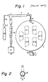
- Fig. 1 is a schematic illustration of a known microwave discharge plasma treatment apparatus of a comparable example. Resin parts used for motor vehicles were subjected to surface treatment in this plasma treatment apparatus. The degree of surface was not uniform, among the parts as well as among the positions within each part, due to the large size and the complicated configuration of those parts.
- a reaction chamber 1 a microwave oscillator 2, an isolator 3 (Toshiba Corp.), a power monitor 4 (Toshiba Corp.) a three- stab tuner 5 (Toshiba Corp.), a plasma generating furnace 6, a plasma generating pipe 7, a quartz pipe 8, a plasma introducing port 9, a plasma-irradiating pipe 12, a discharge port 15 for evacuating the reaction chamber 1, a gas supply conduit 16, a flow meter 17, a gas bomb 18, a waveguide 19 and sample work pieces S1 to S6.
- the sample workpieces were so located that the distance H between the plasma injection nozzle made of the glass pipe 12 and the surfaces of the sample workpieces, along the bisector of the angle a, was 500 mm or 1000 mm.
- Demineralized water of 5 u) in quantity was dropped on the plasma-treated surface of the PP resin sample workpieces.
- a contact angle measuring instrument Karl Fischer, Model: CA-A was used for the measurement of the contact angle.
- the ambient air conditions were 20°C and 50 to 60% RH.
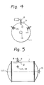
- Figs. 4 and 5 show a plasma treatment apparatus embodying this invention, which comprises plasma diffusers 114 and 115 having vanes disposed on the inner wall of the reaction chamber 1 for improving the effects of diffusion of the plasma flow in the reaction chamber 1.
- the plasma introducing port 9 is provided in the left hand area of the cylindrical wall of the reaction chamber 1, while the discharge port 15 is provided on the center line 117 at the right end of the reaction chamber 1.
- the plasma diffusers 114 and 115 are provided at the same positions as the plasma introducing port 9 with regard to the longitudinal direction of the reaction chamber 1, but separated by about 60° therefrom.
- the plasma irradiating pipe 12 extends perpendicularly to the center axis of the plasma introducing port 9 and in the longitudinal direction of the reaction chamber 1.
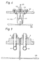
- Fig. 6 shows plasma diffusers 114 and 115 in detail.
- a vane 126 and a drive motor 120 therefor are mounted by a mounting member 121.
- a leading line 125 of the drive motor 120 is sealed by a connector 124 and a plate member 122 mounted on the outer wall of the reaction chamber 1, the inside of which is maintained in the vacuum.
- the plate member 122 is sealed by an 0-ring seal 123 with respect to the outer wall of the reaction chamber 1.
- the drive motor 120 may also be provided on the outer wall of the reaction chamber 1.
- the uniform distribution of the plasma density is established within the reaction chamber 1 by the fact that the plasma introduced into and irradiated in the reaction chamber 1 is diffused in the longitudinal direction of the reaction chamber 1 by the plasma diffusers 114 and 115, then a flow of plasma toward the discharge port 15 is formed.
- the plasma diffuser 114, 115 may also be constituted as shown in Fig. 7. Namely, a plasma diffusing vane 126 which is provided in the vicinity of plasma introducing ports 9 is rotated by virtue of the flow of plasma radiated from the plasma irradiating pipe 12, in place of being rotated by a drive motor.
- the plasma diffusing vane 126 can also be provided in the vicinity of the discharge port 15, although not shown in the drawings, so as to be rotated by virtue of the flow of discharge.
- the positions, sizes, members and etc. of the plasma introducing port 9, discharge port 15, and plasma diffuser 114, 115, and the revolutional speed of the plasma diffusing vane 126 can be advantageously selected in view of the numbers, shapes, sizes and etc. of the workpieces to be treated.
- the plasma introducing port 9 is provided at the center of the cylindrical wall of the reaction chamber 1 (Fig. 11), the discharge port 15 is provided at the opposite position on the cylindrical wall, and the plasma diffusers 114 and 115 are provided at the left and right ends, respectively, on the longitudinal center line of the reaction chamber 1.
- Figs. 8 through 11 the effects of plasma treatment of the workpieces, at the various positions in the reaction chamber 1 are illustrated by lines indicating the distribution of contact angle (6).
- the conditions of treatment were as follows:
- Fig. 8 shows the results of experiment using a plasma treatment apparatus as shown in Figs. 4 and 5, but not actuating the plasma diffusing vanes 126.
- Fig. 9 shows the results of experiment using the same apparatus and actuating the plasma diffusing vanes 126 at 20 to 60 RPM. As is evident from the comparative examination, it is understood that more wide and uniform distribution of the plasma density can be obtained and uniform plasma treatment over the entire surfaces of the workpieces was attained regardless of the location and the configuration of the workpieces in the case of Fig. 9 as compared to the case of Fig. 8.
- Figs. 12 and 13 show a further embodiment of the plasma treatment apparatus, in which, deflecting plates 101 made of stainless steel, such as SUS, are arranged in the horizontal direction (in the direction perpendicular to the vertical direction of the workpieces) A, B, C, D and attached to the inner wall of the reaction chamber 1.
- the deflecting plates 101 a, c and e are arranged in the left hand side, and the deflecting plates 101 b, d and f are arranged in the right hand side.
- the lengths of the deflecting plates 101a to 101f towards the interior of the reaction chamber 1 in downstream direction of the plasma flow increase.
- deflecting plates 101 made of stainless steel, such as SUS
- the most downstream side deflecting plates 101e and 101f have substantially the same length as the deflecting plates 101c and 101d, for avoiding the inside space of the reaction chamber 1 from reducing too much in view of the reaction chamber 1 having cylindrical shape.
- the deflecting plates 101a-1, 101a-2, ... in the same horizontal level have the same length and are regularly spaced in rows; successive rows are staggered with respect to the circumferential direction of the reaction chamber 1.
- Figs. 14 and 15 show another embodiment of the plasma treatment apparatus having deflecting plates 102.
- the reaction chamber 1 is in the shape of a rectangular vertical column, in which a plurality of workpieces A to D are arranged in the vertical direction.
- the plasma-irradiating pipe 12 is provided at the central position of an upper wall of the rectangular reaction chamber 1, while the discharge port 15 is provided at the central portion of a bottom wall of the reaction chamber 1.
- a plurality of deflecting plates 102 made of stainless steel are arranged perpendicularly to the vertical direction of the rectangular reaction chamber 1.
- the horizontal lengths of the deflecting plates 102a-h towards the interior of the reaction chamber increase in the downstream direction of the plasma flow.
- These deflecting plates 102a-h, 102a-1-102h-1 are regularly spaced in rows with respect to the horizontal direction along the inside wall, as in the embodiment shown in Figs. 12 and 13 and staggered in the vertical direction.
- deflecting plates 101a-f, 102a-h are (horizontally) arranged perpendicularly to the vertical direction of the workpieces in the embodiments shown in Figs. 12 through 15, deflecting plates 103 may be inclined towards the interior of the reaction chamber 1 and substantially in the direction of the flow of plasma as an embodiment shown in Fig. 16. Otherwise, the deflecting plates 103 can be constructed so that the angle thereof is changeable according to the sizes, shapes, numbers, and etc. of the workpieces. In any case, the deflecting plates 103 can be made of any material, such as stainless steel, for example SUS as mentioned above, which may not cause the deactivation of the plasma and may not be affected itself, when plasma gas is exposed thereon.
- a part of irradiated plasma after having been collided to the workpieces, flows along the inside wall of the reaction chamber 1.
- the flow of plasma is, then, deflected toward the workpieces A to D by the deflecting plates 103, as shown by arrows in Figs. 12, and spread to the various portions within the reaction chamber 1 so that the workpieces are uniformly treated by plasma, which is then discharged through the discharge port 15 to the outside of the reaction chamber 1.
- the uniform distribution of the plasma density is established within the reaction chamber 1 by the deflecting plates and even in the plasma treatment of comparatively large workpieces of complicated configuration, uniform plasma treatment over the entire surfaces of the workpieces is attained regardless of their location and configuration.
- these effects can be attained by these deflecting plates of simple construction, it is not necessary to increase the numbers of plasma irradiating pipes, and the accompanying oscillators, wave-transmitting pipes, plasma generating pipes and etc.
Claims (7)
Applications Claiming Priority (6)
| Application Number | Priority Date | Filing Date | Title |
|---|---|---|---|
| JP29371/83 | 1983-02-25 | ||
| JP29372/83 | 1983-02-25 | ||
| JP58029372A JPS59155442A (ja) | 1983-02-25 | 1983-02-25 | プラズマ処理装置 |
| JP58029371A JPS59155441A (ja) | 1983-02-25 | 1983-02-25 | プラズマ処理方法および装置 |
| JP38204/83 | 1983-03-10 | ||
| JP3820483A JPS59164340A (ja) | 1983-03-10 | 1983-03-10 | プラズマ処理装置 |
Related Child Applications (2)
| Application Number | Title | Priority Date | Filing Date |
|---|---|---|---|
| EP19890105490 Division EP0326191A3 (fr) | 1983-02-25 | 1984-02-23 | Appareil et méthode pour le traitement par plasma de matériau résineux |
| EP89105490.0 Division-Into | 1984-02-23 |
Publications (3)
| Publication Number | Publication Date |
|---|---|
| EP0117541A2 EP0117541A2 (fr) | 1984-09-05 |
| EP0117541A3 EP0117541A3 (en) | 1987-04-15 |
| EP0117541B1 true EP0117541B1 (fr) | 1990-05-02 |
Family
ID=27286538
Family Applications (1)
| Application Number | Title | Priority Date | Filing Date |
|---|---|---|---|
| EP84101935A Expired EP0117541B1 (fr) | 1983-02-25 | 1984-02-23 | Appareil pour le traitement par plasma de matériau résineux |
Country Status (4)
| Country | Link |
|---|---|
| US (3) | US4595570A (fr) |
| EP (1) | EP0117541B1 (fr) |
| AU (2) | AU548915B2 (fr) |
| DE (1) | DE3482155D1 (fr) |
Families Citing this family (11)
| Publication number | Priority date | Publication date | Assignee | Title |
|---|---|---|---|---|
| GB8333665D0 (en) * | 1983-12-16 | 1984-01-25 | Lilly Industries Ltd | Organic compounds |
| JPS61225819A (ja) * | 1985-03-29 | 1986-10-07 | Fuji Electric Co Ltd | レ−ザcvd装置 |
| US5007983A (en) * | 1988-01-29 | 1991-04-16 | The United States Of America As Represented By The Administrator Of National Aeronautics And Space Administration | Etching method for photoresists or polymers |
| DE4437050A1 (de) * | 1994-10-17 | 1996-04-18 | Leybold Ag | Vorrichtung zum Behandeln von Oberflächen von Hohlkörpern, insbesondere von Innenflächen von Kraftstofftanks |
| US6013155A (en) * | 1996-06-28 | 2000-01-11 | Lam Research Corporation | Gas injection system for plasma processing |
| EP0958401B1 (fr) | 1996-06-28 | 2004-09-08 | Lam Research Corporation | Appareil et procede pour le depot en phase vapeur ou pour gravure cathodique parprocede chimique au plasma haute densite |
| US6184158B1 (en) | 1996-12-23 | 2001-02-06 | Lam Research Corporation | Inductively coupled plasma CVD |
| WO1998058731A2 (fr) * | 1997-06-20 | 1998-12-30 | Flowgenix Corporation | Dispositif pour exposer des substrats a des radicaux en phase gazeuse |
| US6042687A (en) * | 1997-06-30 | 2000-03-28 | Lam Research Corporation | Method and apparatus for improving etch and deposition uniformity in plasma semiconductor processing |
| CH697092A5 (de) * | 1998-12-24 | 2008-04-30 | Sulzer Metco Ag | Anordnung für eine Plasmaspritzanlage. |
| EP2937890B1 (fr) * | 2014-04-22 | 2020-06-03 | Europlasma nv | Appareil de revêtement au plasma avec un diffuseur de plasma et procédé prévenant la décoloration d'un substrat |
Family Cites Families (13)
| Publication number | Priority date | Publication date | Assignee | Title |
|---|---|---|---|---|
| JPS5211175A (en) * | 1975-07-18 | 1977-01-27 | Toshiba Corp | Activated gas reacting apparatus |
| JPS5378170A (en) * | 1976-12-22 | 1978-07-11 | Toshiba Corp | Continuous processor for gas plasma etching |
| JPS5329076A (en) * | 1976-08-31 | 1978-03-17 | Toshiba Corp | Plasma treating apparatus of semiconductor substrates |
| JPS53121469A (en) * | 1977-03-31 | 1978-10-23 | Toshiba Corp | Gas etching unit |
| JPS5565436A (en) * | 1978-11-10 | 1980-05-16 | Mitsubishi Electric Corp | Plasma treatment device |
| JPS6029295B2 (ja) * | 1979-08-16 | 1985-07-10 | 舜平 山崎 | 非単結晶被膜形成法 |
| JPS56147832A (en) * | 1980-04-16 | 1981-11-17 | Toshiba Corp | Surface treating device |
| JPS5712032A (en) * | 1980-06-26 | 1982-01-21 | Sekisui Chem Co Ltd | Apparatus for treatment with activated gas |
| JPS5740586A (en) * | 1980-08-22 | 1982-03-06 | Toshiba Corp | Treatment of fluorescent substance and its device |
| US4434188A (en) * | 1981-12-17 | 1984-02-28 | National Institute For Researches In Inorganic Materials | Method for synthesizing diamond |
| US4501766A (en) * | 1982-02-03 | 1985-02-26 | Tokyo Shibaura Denki Kabushiki Kaisha | Film depositing apparatus and a film depositing method |
| JPS58170536A (ja) * | 1982-03-31 | 1983-10-07 | Fujitsu Ltd | プラズマ処理方法及びその装置 |
| JPS58208326A (ja) * | 1982-05-31 | 1983-12-05 | Hashimoto Forming Co Ltd | プラズマ処理方法 |
-
1984
- 1984-02-16 AU AU24672/84A patent/AU548915B2/en not_active Ceased
- 1984-02-23 DE DE8484101935T patent/DE3482155D1/de not_active Expired - Lifetime
- 1984-02-23 EP EP84101935A patent/EP0117541B1/fr not_active Expired
-
1985
- 1985-09-05 US US06/772,208 patent/US4595570A/en not_active Expired - Fee Related
- 1985-11-05 AU AU49368/85A patent/AU578499B2/en not_active Ceased
-
1986
- 1986-01-08 US US06/817,115 patent/US4874453A/en not_active Expired - Fee Related
-
1989
- 1989-02-08 US US07/307,509 patent/US4919745A/en not_active Expired - Fee Related
Also Published As
| Publication number | Publication date |
|---|---|
| AU578499B2 (en) | 1988-10-27 |
| AU4936885A (en) | 1986-04-24 |
| AU548915B2 (en) | 1986-01-09 |
| EP0117541A3 (en) | 1987-04-15 |
| DE3482155D1 (de) | 1990-06-07 |
| AU2467284A (en) | 1984-10-04 |
| EP0117541A2 (fr) | 1984-09-05 |
| US4919745A (en) | 1990-04-24 |
| US4874453A (en) | 1989-10-17 |
| US4595570A (en) | 1986-06-17 |
Similar Documents
| Publication | Publication Date | Title |
|---|---|---|
| EP0117541B1 (fr) | Appareil pour le traitement par plasma de matériau résineux | |
| EP0120307B1 (fr) | Appareil et procédé pour le traitement au plasma d'un matériau en résine | |
| KR950034531A (ko) | 플라즈마 처리장치 | |
| JP2005095744A (ja) | 絶縁部材の表面処理方法及び絶縁部材の表面処理装置 | |
| US20080280065A1 (en) | Method and Device for Generating a Low-Pressure Plasma and Applications of the Low-Pressure Plasma | |
| EP0152511B1 (fr) | Dispositif et procédé pour le traitement au plasma de matière plastique | |
| US4690097A (en) | Apparatus and method for plasma treatment of resin material | |
| JPS63141318A (ja) | 試料処理用ガス排気装置 | |
| CN111785603A (zh) | 一种微波等离子清洗机 | |
| EP0326191A2 (fr) | Appareil et méthode pour le traitement par plasma de matériau résineux | |
| EP0790113B1 (fr) | Procédé de nettoyage d'un moule de vulcanisation | |
| US4786522A (en) | Method for plasma treatment of resin material | |
| JPS59155442A (ja) | プラズマ処理装置 | |
| JPS629302Y2 (fr) | ||
| JPS59155440A (ja) | プラズマ処理装置 | |
| JPS638975B2 (fr) | ||
| JPS5986630A (ja) | プラズマ処理を施す方法および装置 | |
| JPH04312797A (ja) | プラズマ発生装置 | |
| JPS59155441A (ja) | プラズマ処理方法および装置 | |
| JPS6217455Y2 (fr) | ||
| JPH02267290A (ja) | マイクロ波プラズマ処理装置 | |
| JPH0315531Y2 (fr) | ||
| JPS61190948A (ja) | 膜形成装置 | |
| JPH0570956A (ja) | 有磁場マイクロ波吸収プラズマ処理装置 | |
| KR100557761B1 (ko) | 반도체 제조용 공정챔버 |
Legal Events
| Date | Code | Title | Description |
|---|---|---|---|
| PUAI | Public reference made under article 153(3) epc to a published international application that has entered the european phase |
Free format text: ORIGINAL CODE: 0009012 |
|
| 17P | Request for examination filed |
Effective date: 19840223 |
|
| AK | Designated contracting states |
Designated state(s): DE FR GB |
|
| PUAL | Search report despatched |
Free format text: ORIGINAL CODE: 0009013 |
|
| AK | Designated contracting states |
Kind code of ref document: A3 Designated state(s): DE FR GB |
|
| 17Q | First examination report despatched |
Effective date: 19880927 |
|
| GRAA | (expected) grant |
Free format text: ORIGINAL CODE: 0009210 |
|
| AK | Designated contracting states |
Kind code of ref document: B1 Designated state(s): DE FR GB |
|
| XX | Miscellaneous (additional remarks) |
Free format text: TEILANMELDUNG 89105490.0 EINGEREICHT AM 23/02/84. |
|
| REF | Corresponds to: |
Ref document number: 3482155 Country of ref document: DE Date of ref document: 19900607 |
|
| ET | Fr: translation filed | ||
| PLBE | No opposition filed within time limit |
Free format text: ORIGINAL CODE: 0009261 |
|
| STAA | Information on the status of an ep patent application or granted ep patent |
Free format text: STATUS: NO OPPOSITION FILED WITHIN TIME LIMIT |
|
| 26N | No opposition filed | ||
| REG | Reference to a national code |
Ref country code: GB Ref legal event code: 746 |
|
| PGFP | Annual fee paid to national office [announced via postgrant information from national office to epo] |
Ref country code: FR Payment date: 19930209 Year of fee payment: 10 |
|
| PGFP | Annual fee paid to national office [announced via postgrant information from national office to epo] |
Ref country code: GB Payment date: 19930215 Year of fee payment: 10 |
|
| PGFP | Annual fee paid to national office [announced via postgrant information from national office to epo] |
Ref country code: DE Payment date: 19930308 Year of fee payment: 10 |
|
| REG | Reference to a national code |
Ref country code: FR Ref legal event code: DL |
|
| PG25 | Lapsed in a contracting state [announced via postgrant information from national office to epo] |
Ref country code: GB Effective date: 19940223 |
|
| GBPC | Gb: european patent ceased through non-payment of renewal fee |
Effective date: 19940223 |
|
| PG25 | Lapsed in a contracting state [announced via postgrant information from national office to epo] |
Ref country code: FR Effective date: 19941031 |
|
| PG25 | Lapsed in a contracting state [announced via postgrant information from national office to epo] |
Ref country code: DE Effective date: 19941101 |
|
| REG | Reference to a national code |
Ref country code: FR Ref legal event code: ST |