EP0116480A1 - Gehäuse zum Verbinden und Mischen optischer Fasern - Google Patents
Gehäuse zum Verbinden und Mischen optischer Fasern Download PDFInfo
- Publication number
- EP0116480A1 EP0116480A1 EP84400006A EP84400006A EP0116480A1 EP 0116480 A1 EP0116480 A1 EP 0116480A1 EP 84400006 A EP84400006 A EP 84400006A EP 84400006 A EP84400006 A EP 84400006A EP 0116480 A1 EP0116480 A1 EP 0116480A1
- Authority
- EP
- European Patent Office
- Prior art keywords
- fibers
- box according
- panel
- compartment
- loops
- Prior art date
- Legal status (The legal status is an assumption and is not a legal conclusion. Google has not performed a legal analysis and makes no representation as to the accuracy of the status listed.)
- Granted
Links
- 230000003287 optical effect Effects 0.000 title description 5
- 239000000835 fiber Substances 0.000 claims abstract description 116
- 239000013307 optical fiber Substances 0.000 claims abstract description 70
- 238000003825 pressing Methods 0.000 claims description 11
- 230000000712 assembly Effects 0.000 claims description 8
- 238000000429 assembly Methods 0.000 claims description 8
- 230000000149 penetrating effect Effects 0.000 claims description 4
- 238000005452 bending Methods 0.000 claims description 2
- 230000008901 benefit Effects 0.000 description 6
- 210000004907 gland Anatomy 0.000 description 4
- 238000003780 insertion Methods 0.000 description 4
- 230000037431 insertion Effects 0.000 description 4
- 238000000034 method Methods 0.000 description 4
- 238000005192 partition Methods 0.000 description 4
- 230000005540 biological transmission Effects 0.000 description 2
- 238000006677 Appel reaction Methods 0.000 description 1
- 241001527806 Iti Species 0.000 description 1
- 241000212322 Levisticum officinale Species 0.000 description 1
- 229920000297 Rayon Polymers 0.000 description 1
- 239000002131 composite material Substances 0.000 description 1
- 239000004020 conductor Substances 0.000 description 1
- 230000008878 coupling Effects 0.000 description 1
- 238000010168 coupling process Methods 0.000 description 1
- 238000005859 coupling reaction Methods 0.000 description 1
- 230000000694 effects Effects 0.000 description 1
- 239000001645 levisticum officinale Substances 0.000 description 1
- 238000012423 maintenance Methods 0.000 description 1
- 238000012986 modification Methods 0.000 description 1
- 230000004048 modification Effects 0.000 description 1
- 230000008520 organization Effects 0.000 description 1
- 230000008569 process Effects 0.000 description 1
- 230000001681 protective effect Effects 0.000 description 1
- 239000002964 rayon Substances 0.000 description 1
- 238000000926 separation method Methods 0.000 description 1
- 238000003756 stirring Methods 0.000 description 1
- 210000002105 tongue Anatomy 0.000 description 1
- 238000013519 translation Methods 0.000 description 1
Images


Classifications
-
- G—PHYSICS
- G02—OPTICS
- G02B—OPTICAL ELEMENTS, SYSTEMS OR APPARATUS
- G02B6/00—Light guides; Structural details of arrangements comprising light guides and other optical elements, e.g. couplings
- G02B6/44—Mechanical structures for providing tensile strength and external protection for fibres, e.g. optical transmission cables
- G02B6/4439—Auxiliary devices
- G02B6/444—Systems or boxes with surplus lengths
- G02B6/4453—Cassettes
- G02B6/4455—Cassettes characterised by the way of extraction or insertion of the cassette in the distribution frame, e.g. pivoting, sliding, rotating or gliding
-
- G—PHYSICS
- G02—OPTICS
- G02B—OPTICAL ELEMENTS, SYSTEMS OR APPARATUS
- G02B6/00—Light guides; Structural details of arrangements comprising light guides and other optical elements, e.g. couplings
- G02B6/44—Mechanical structures for providing tensile strength and external protection for fibres, e.g. optical transmission cables
- G02B6/4439—Auxiliary devices
- G02B6/444—Systems or boxes with surplus lengths
- G02B6/4452—Distribution frames
- G02B6/44526—Panels or rackmounts covering a whole width of the frame or rack
-
- G—PHYSICS
- G02—OPTICS
- G02B—OPTICAL ELEMENTS, SYSTEMS OR APPARATUS
- G02B6/00—Light guides; Structural details of arrangements comprising light guides and other optical elements, e.g. couplings
- G02B6/44—Mechanical structures for providing tensile strength and external protection for fibres, e.g. optical transmission cables
- G02B6/4439—Auxiliary devices
- G02B6/444—Systems or boxes with surplus lengths
- G02B6/44528—Patch-cords; Connector arrangements in the system or in the box
-
- G—PHYSICS
- G02—OPTICS
- G02B—OPTICAL ELEMENTS, SYSTEMS OR APPARATUS
- G02B6/00—Light guides; Structural details of arrangements comprising light guides and other optical elements, e.g. couplings
- G02B6/44—Mechanical structures for providing tensile strength and external protection for fibres, e.g. optical transmission cables
- G02B6/4439—Auxiliary devices
- G02B6/444—Systems or boxes with surplus lengths
- G02B6/4453—Cassettes
- G02B6/4454—Cassettes with splices
Definitions
- the present invention relates generally to the two-to-two connection of the optical fibers of at least two assemblies in which the optical fibers can be distributed circularly or coplanarly. More particularly, it relates to a fiber optic connection box which offers the possibility of carrying out fiber mixing, that is to say connection modifications.
- connection and patching boxes are already disclosed for example in patent applications GB-A-2,040,494, DE-A-3,006,131 and EP - A-0.024.235. All these boxes have a cylindrical structure and are suitable for connecting the ends of the optical fibers of a first cable to the ends of the optical fibers of a second cable.
- the cables enter the box collinearly at its longitudinal axis and through its bases.
- the elementary connection devices are contained in the box at its transverse median plane and each connect the end of an optical fiber of the first cable to the end of an optical fiber of the second cable.
- the connection devices playing the role of splices are generally cylindrical, generally require several support parts requiring a lot of space and must be completely disassembled or replaced if one wishes to modify the connection between fibers.
- certain boxes (GB-A-2,040,494 and DE-A-3,006,131) contain loops of reserves of the optical fibers in order to have sufficient length to access the various connection devices. These reserve loops are housed in the two spaces between the ends of the box and the central support of the connection devices.
- connection and patching operations are long and delicate and require complex and special tools and that the dimensions of the box are very large.
- the object of the present invention is to obviate the preceding drawbacks and in particular to provide a connection and patching box having reduced dimensions although the box offers a large connection capacity and easy accessibility to the fibers. optical and fiber connection devices.
- the invention also aims to produce low cost connections using a reduced number of parts and a very small number of parts to be dismantled.
- the lifetime of the optical fibers is also considered, which mainly depends, during connections, on the minimum radius of curvature that an optical fiber can undergo without influencing its physical characteristics.
- the invention essentially provides two embodiments of a box, one relating to direct mixing between two optical fiber assemblies and the other relating to mixing by garters between optical fiber assemblies.
- a connection and patch box of first and second sets of optical fibers composed of a first receptacle and of a second stackable receptacle and containing several connection devices for each connecting the end of a optical fiber of the first set at the end of an optical fiber of the second set is characterized in that it comprises a removable panel separates the box into a first compartment which con t ient of flat loops of the fiber - the first set penetrating through at least one hole of the first receptacle, and into a second compartment which contains the connection devices, the end sections of the fibers of the first assembly which pass through an orifice in the panel and the ends of which are inserted respectively into the connection devices, and flat loops of the fibers of the second set which penetrate through at least one hole of the second receptacle and whose ends ities are inserted respectively into the connection devices.
- a connection and mixing box for two sets of optical fibers composed of a first receptacle and of a second stackable receptacle and containing several connection devices which are each connected to the end of a optical fiber of an assembly, is characterized in that it contains a removable panel separating the box into a first compartment which is at least partly in the first receptacle and which contains the end sections of the fibers of the two assemblies, two series of connection devices assigned respectively to the sets of optical fibers and to the practically circular flat loops of garters in the form of optical fibers each connecting a connection device of one series to a connection device of the other series, and in a second compartment which contains practically circular flat loops of the fibers of the two sets penetrating through holes of the second receptor tackle.
- the ends of the optical fibers of all the assemblies in the box according to the second embodiment can be pre-wired, and only changes in the connections of the jumpers will allow the connections between the fibers to be mixed, which increases the reliability of the optical fibers of the assemblies which are only handled once.
- the box can have several panels pivoting around the same axis, which increases the connection capacity in view of the relatively small volume of the box. The separation between the compartments delimited by the panels limits the risks of undesirable connections.
- Fig. 1 schematically recalls, according to the prior art, the connection of two cables Ca and Cb with respective optical fibers Fa and Fb by means of elementary connection devices R.
- An elementary connection device R is hereinafter called “connection” and connects the end of an optical fiber Fa of the first cable Ca to the end of an optical fiber Fb of the second cable Cb.
- BO connection box according to the prior art which contour is represented by a rectangle in thin line in FIG. 1- is cylindrical. The bottom of the box and the cover of the box respectively form lower and upper shells, the junction plane of which is in the longitudinal alignment axis of the opposite ends of the cables Ca and Cb.
- the fibers Fa and Fb are spread out from the stripped ends of the cables Ca and Cb.
- the means for supporting the fittings R are for example composed of circlips in each of which a fitting is fitted.
- the connections are arranged on either side along the small median axis, here vertical, of the BO box. Between the end of each cable Ca, Cb and the connections R, a relatively large space can be provided to accommodate large sections of the optical fibers Fa, Fb so that the operator can have a sufficient length to pull the fibers during connections.
- the sets Ea and Eb of optical fibers are composed of several respective optical cables Ca l , Ca 2 , ... Ca p , ... Ca p-1 , Ca p , and Cb l , Cb 2 , ... Cb p , ... Cb p-1 , Cbp where the whole index p varies between 1 and P.
- Each cable Ca, Cb contains M respective optical fibers Fa, Fb.
- Each cable may for example comprise a cylindrical rod helically grooved in each groove of which an optical fiber is arranged, or a central cylindrical support element around which the optical fibers are coated, either in a gelling component, or in individual tubes, or else. again, a flat grooved support. on which are kept coplanar in sheet or ribbon optical fibers.
- Several elementary cables such as Ca p or Cb p can constitute sub-cables which are enclosed in the common envelope. of a composite cable.
- the elementary fittings or connection devices to which the present invention relates are preferably types as described in the European patent application 83401797.2 filed on September 14 , 1983. and in the European patent application filed today in the names of the current applicants.
- a connection of the ends of two optical fibers Fa and Fb comprises a housing which contains a fiber support means having a central groove for receiving the ends of the fibers and support surfaces of the fiber sheaths on either side of the groove, and which also contains first means for pressing the ends of the fibers in the groove and second means for pressing the sheaths of the fibers on the bearing surfaces.
- the first and second pressing means are slidably mounted in the housing above the support means and are urged against the support means by respective elastic means.
- a connection of the ends of two fibers Fa and Fb comprises a base having a central groove for receiving the ends of the two fibers, and means for pressing the ends of the fibers in the groove.
- the pressing means are constituted by a spring plate, for example in a U, of which a first end applies by its own bending the ends of the fibers in the groove and whose second end is integral with the base.
- the thin parallelepipedic connections are inserted between parallel partitions, preferably removable, which are fixed on a flat support S forming a compact parallelepiped strip.
- the support S comprises, between two adjacent partitions, flexible lugs, tongues, bosses, or the like for locking a connection, for example by means of two lateral notches of the connection.
- Such a connector stack thus has a reduced overall size and makes it possible, if necessary, to connect optical fibers without any withdrawal of the connectors because the ends of the means for pressing the connectors are accessible from above the bar S by means of '' a simple handling tool.
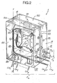
- FIG. 2 A direct connection and patching box 1 according to the invention is shown in FIG. 2.
- first cables Ca l to Cap of the first set Ea second cables Cb1 to Cbp of the second set Eb, fittings R and a bar S as described above.
- Box 1 is parallelepiped. It comprises a first receptacle 10, a second receptacle 11 and a removable panel 12.
- the first receptacle 10 and the second receptacle 11 form the bottom and the cover of the box 1 and are stackable.
- the panel 12 forms a rectangular partition between the bottom and the cover and thus divides the box into a first parallelepipedal rear compartment 100 which is delimited by the walls of the bottom 10, and in a second parallelepipedic front compartment 110 which is delimited by the walls of the cover 11.
- the panel 12 can be fixed on the front edges of the bottom or on the rear edges of the cover.
- the panel is mounted on the bottom in order to make the connections R of the bar S contained in the front compartment 110 more accessible.
- the panel 12 can be fixed to the front edges of the bottom by screwing, snap-fastening or the like or preferably can be pivotally mounted about the hinge axis Y'Y of a hinge along the front edge of a bottom wall 10, such as the side 101 shown in FIG. 2. In the latter case, the panel 12 is pivoted towards the outside of the bottom 10 around the axis Y'Y to coil the optical fibers Fa and then is folded against stops in the vicinity of the edges of the three other sides 102, 103 and 104 from the bottom 10.
- the first cables Ca 1 to Ca p enter the rear compartments 100 through holes 105 which are provided in at least one of the sides, such as 102, of the bottom 10 adjacent to the side 101 supporting the hinge of the panel 12, and preferably in the three sides 102, 103 and 104.
- the holes 105 are optionally each fitted with a cable gland 106, for example of the rubber sleeve type, into which a sheathed end of the respective cable Ca is threaded and which seals the connection between the cable and the box.
- the optical fibers Fa of the cables Ca 1 to Ca p are released and are then gathered in a bundle.
- the fibers Fa leaving the cables Ca l to Ca p are slid into rectilinear guide means 120-121 which are parallel and adjacent to the pivot axis Y'Y of the panel 12 and which are fixed to the rear face 122 of the panel 12.
- the rectilinear guide means can be constituted by at least two tube sections or two preferably split rings 120 and 121 having their axis aligned and parallel to the axis Y'Y.
- the distance between the end rings 120 and 121 shown in FIG. 2 can be equal to approximately 400 times the nominal diameter of an optical fiber so that the optical fibers Fa can work in bending-torsion.
- the bundle of optical fibers Fa is then coiled "in wafer", that is to say flat, against the rear face 122 of the panel 12 in several Ba circular loops which are practically circular and superimposed.
- the Ba loops allow the operator to have sufficient lengths of the fibers Fa to prepare the ends of the fibers and introduce them into the fittings R.
- the Ba loops constitute reserves of fibers in the event of an incident involving the obligation to redo the connections or cutting the fiber ends again.
- coplanar gutters 123 with cross section in U are provided on the face rear 122 of panel 12.
- four gutters 123 are arranged along the sides of a square which encloses a circle with a radius greater than r.
- the gutters can be arranged in a configuration other than square, such as rectangular, oval, etc.
- the free branches of the gutters 123 towards the interior of the rear compartment 100 are pre-profiled in an isosceles trapezoid and are disjoint in order to allow the insertion of the fibers Fa and their maintenance in loops of ease Ba.
- In place of the gutters or together with these can be used quick couplings in the form of a ring which surround the bundle of fibers Fa and whose front rods are snapped into holes distributed circularly on the rear face 122 of the panel 12.
- Fig. 2 only a few ease loops Ba of the fiber bundle Fa have been shown so as not to overload the drawing, although in practice a dozen ease loops can be formed for each optical fiber by turning following clockwise.
- the optical fibers Fa are then drawn, here- from the lower gutter 123, through an oblong orifice 124 of the panel 12 between the guide means 120-121 and the rear coiling surface defined by the ease loops Ba.
- the orifice 124 is for example made at mid-height between the aligned rings 120 and 121 and the bottom of the left vertical gutter 123, as shown in FIG. 2.
- the bundle of Fa fibers thus opens onto the front face 125 of the panel 12 with a length sufficient to allow the insertion of the Fa fibers into the fittings R.
- the panel 12 pivots about the axis Y ' Y and is folded down on the front face of the bottom 10 to close the rear compartment 100 and be held there in this position by a suitable locking device.
- the locking device can be constituted by one or more latches which are fixed on the front edge of the bottom 10 receiving in abutment the free edge of the parallel panel and opposite to the axis Y'Y. Two such latches are shown schematically at 107 in FIG. 2.
- the stack of fittings R to R MP embedded between the partitions of the bar S is fixed vertically on the front face 125 for example by screws.
- the fittings R conform to one of those described in the European patent application 83401797.2 and the European patent application filed today.
- the tall rectangular faces of the fittings R are arranged horizontally.
- the vertical edges of the fittings R giving access to the pressing means with a view to clearing the grooves and threading the ends of the fibers therein are opposite the large internal face of the cover I1.
- the ends of the end sections of the fibers Fa emerging from the orifice 124 are threaded into a first half of the grooves of the connectors R, at the rate of one fiber Fa per connector.
- the number of connections R is equal to or greater than the total number M ⁇ P of the fibers contained in a set Ea, Eb.
- the first cables Ca constitute "pre-wired" cables, which means that each fiber Fa of the first set Ea is permanently assigned a connection R, the connection of the connections being effected by the variable choice of a connection R for each of the optical fibers Fb of the second set Eb.
- protective grids 117 cover the end sections of the fibers Fa after insertion into the fittings R and are fixed to the front face 125 of the panel.
- the operator then coils flat and inserts the fibers Fb into the fittings R.
- the second cables Cb 1 to Cbp are passed through holes 115 which are provided in at least one of the sides 111, 112, 113 and 114 of the cover 11 and which are optionally each fitted with a cable gland 116, as shown in FIG. 2.
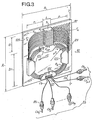
- the fibers Fb of the second cables have flourished in the front compartment 110, in a manner analogous to that of the fibers Fa, the fibers Fb are combined in a bundle which is coiled flat in practically circular and superimposed loops of ease. Bb in the opposite direction to that of the loops Ba of the fibers Fa which are coiled against, viewed from the front face 125 of the panel 12.
- the loops Bb provide sufficient extra lengths of fibers Fb to conveniently prepare the ends of the fibers Fb and their insertion in the halves -left in Fig. 3- grooves of the fittings, and also make it possible to overcome any incidents causing a connection resumption and to carry out the mixing.
- Brewing consists, for example, in removing the end of an Fb fiber which is initially inserted into a fitting such as R 1 , and insert it into another fitting such as R p (Fig. 3).
- the coiling area of the fibers Fb is delimited in the lower part of the front face 125 of the panel 12, under the bar S, by four coplanar gutters 126 which have a mutual arrangement in square similar to that of the gutters 123 on the rear face 122 of the panel.
- Each gutter 126 also has a U-shaped section, the large free front branch of which is profiled in an isosceles trapezoid and the small rectangular branch of which is fixed to the front face 125 of the panel 12 in the area for coiling the fibers Fb. As shown in Fig.
- the fibers Fb leaving the ends of the second cables Cb l to Cb P at the level of the cable glands 116 in the sides of the cover 11 penetrate into the coiling area through vertical slots 127 of the trapezoidal branch of the horizontal gutter lower 126, then are coiled in the four gutters 126 in several loops Bb and finally exit from the upper end of the left vertical gutter 126 for the introduction of the ends of the fibers Fb in the left halves of grooves of fittings R.
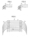
- the identification of the fibers Fa, Fb can be carried out by means of rings 118 shown in FIG. 4, or by means of flags 119 shown in FIG. 5 each threaded around the sheathed end of a fiber Fa, Fb and comprising a respective number, or alternatively by means of a numbering near the two ends of the fittings R in the bar S as shown in FIG. 6.
- the cover 11 is superimposed on the bottom 10 and fixed to the latter by screwing, snap-fastening or the like.
- connection and patching relates to patching between several cables Ca and Cb, as shown diagrammatically in FIG. 7.
- the fibers Fa, Fb of each cable Ca, Cb are introduced respectively into connections Ra, Rb of a respective bar Sa, Sb.
- Each connection Ra is then connected to one of the connections Rb by a jumper J which is constituted by an optical fiber and which is arranged in the space between the two parallel bars Sa and Sb.
- the patching method with garters doubles the number of connections to be made and, therefore, significantly doubles the duration and cost of the operation for a number of connections equal to that of the "direct" patching process (Fig. 1).
- the stirring by garters advantageously makes it possible to definitively prewire the fibers Fa and Fb in the respective connectors Ra and Rb, that is to say to permanently assign each fiber entering the box to a connector.
- the connection of a fiber Fa of a first cable Ca to a fiber Fb of a second cable Cb is carried out separately by a jumper J and on request. Garters are easier to handle and store in coiling areas than cable bundles.
- any connection between any fiber Fa and any fiber Fb can be carried out either by reusing a jumper already in the box, or by introducing a new jumper or a free jumper and by disconnecting the ends of the initial jumpers connected to the fibers to be connected.
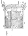
- connection and patching box with jumpers 2 shown in Figs. 8 to 10 is provided for connecting a fiber Fa, Fb of any cable Ca, Cb among a plurality of cables to an optical fiber Fa, Fb of another cable of this plurality of cables. It is also parallelepipedic and is constituted by a cover 20 and a bottom 21.
- the box contains in a first compartment 200 several panels pivotally mounted around a vertical axis Y'Y integral with the bottom 21 and arranged in a vertical corner, here left, from the back.
- Figs. 8 to 10 is provided for connecting a fiber Fa, Fb of any cable Ca, Cb among a plurality of cables to an optical fiber Fa, Fb of another cable of this plurality of cables. It is also parallelepipedic and is constituted by a cover 20 and a bottom 21.
- the box contains in a first compartment 200 several panels pivotally mounted around a vertical axis Y'Y integral with the bottom 21 and arranged in a vertical corner, here left, from the back.
- each panel 22 1 , 22 2 has two arms 228 1 , 228 2 which are articulated around the axis Y'Y without translation along this axis and which are bent so that the panels can be arranged parallel to the large faces of the cover 20 and the bottom 21 when the box is closed.
- each panel can pivot about 180 ° towards the outside of the bottom 21.
- each panel 22 1 , 22 2 On one of the large vertical rectangular faces 222 1 , 222 2 of each panel 22 1 , 22 2 are fixed in parallel two horizontal bars Sa 1 and Sb 1 , Sa 2 and Sb 2 , of connections Ra 1 and Rb 1 , Ra 2 and Rb 2 . Between the two bars on the same panel is provided a coiling area 223 1 , 223 2 of garters. J 1 , J 2 to each connect a connector of one of the two bars to a connector of the other bar.
- panels such as 22 1 and 22 2 at the ends of the stack of panels have large faces 225 1 and 225 2 respectively opposite the internal faces of the cover 2 0 and du.fond 21 which do not support any bar of connections.
- the length of a garter is variable and depends on its path followed between two connections to be connected which can be either on the same panel, or on two respective panels among the plurality of panels.
- the jumper leaving the coiling area of one of the panels travels in guide means 220-221, with tubes or rings, which are partly integral of one of the panels, partly secured to the bottom 21 and partly secured to the other panel, as shown in Figs..8A and 8B.
- These guide means allow a rectilinear passage of the garters along the vertical axis Y'Y of pivoting of the panels.
- the guide means also serve to convey to the respective fittings the end sections of the optical fibers Fa and Fb which can be protected by grids 217 1 and 217 2 shown in Figs. 8A and 8B.
- the panels folded down towards the bottom 21 leave a free compartment 210 between the large internal face of the bottom 21 and the last panel such as 22 2 vis-à-vis the latter.
- the compartment 210 shown in FIG. 10 is available for coiling the incoming fibers Fa and Fb and accessible by pivoting the panels towards the outside of the bottom 21.
- the cables Ca, Cb to be connected penetrate through holes 215a, 215b fitted with cable glands 216a, 216b and practiced in the four sides of the bottom 21. As soon as they enter the bottom, the cables are stripped, but their flexible carrying element, if it exists, is not sawn immediately.
- the load-bearing elements are only sawn out of the sets of gutters where the fibers Fa and Fb are routed by rectilinear passage in the guide means 220-221 along the pivot axis Y'Y, towards the respective fittings on the panels.
- Some cables such as C'a and C'b, do not need to be patched, but can only be connected two by two.
- auxiliary means for guiding, coiling and locating the fibers and garters so as not to overload the figures.
- These means are practically analogous to those described for the direct patching box 1 which can also contain several panels which pivot about the same axis and which each support guide and coiling means and a connector strip for the direct patching of the fibers of two respective sets.
- connection bar on the panel 12 of the direct patch box 1 can be replaced by two parallel connection bars in order to effect a patching by garters.
- each connector of a strip makes it possible to connect an optical fiber of the respective assembly Ea, Eb to a jumper J the other end of which is inserted into a fitting of the other strip.
- the front face 125 of the panel 12 (Fig. 3) is analogous to the face 222 1 , 222 2 of a panel 22 1 , 22 2 (Fi g s. 8 and 9) and supports coplanar parts in the form of a gutter or rings which are equally distributed around one or more circles and which contain the loops of the garters coiled flat between the two bars.
Applications Claiming Priority (2)
| Application Number | Priority Date | Filing Date | Title |
|---|---|---|---|
| FR8300075A FR2538918A1 (fr) | 1983-01-05 | 1983-01-05 | Boite de raccordement et de brassage pour fibres optiques |
| FR8300075 | 1983-01-05 |
Publications (2)
| Publication Number | Publication Date |
|---|---|
| EP0116480A1 true EP0116480A1 (de) | 1984-08-22 |
| EP0116480B1 EP0116480B1 (de) | 1987-05-20 |
Family
ID=9284675
Family Applications (1)
| Application Number | Title | Priority Date | Filing Date |
|---|---|---|---|
| EP84400006A Expired EP0116480B1 (de) | 1983-01-05 | 1984-01-04 | Gehäuse zum Verbinden und Mischen optischer Fasern |
Country Status (5)
| Country | Link |
|---|---|
| US (1) | US4717231A (de) |
| EP (1) | EP0116480B1 (de) |
| CA (1) | CA1250464A (de) |
| DE (1) | DE3463851D1 (de) |
| FR (1) | FR2538918A1 (de) |
Cited By (22)
| Publication number | Priority date | Publication date | Assignee | Title |
|---|---|---|---|---|
| FR2561788A1 (fr) * | 1984-03-26 | 1985-09-27 | Silec Liaisons Elec | Cassettes pour fibres optiques et boite de raccordement utilisant de telles cassettes |
| EP0178179A2 (de) * | 1984-10-11 | 1986-04-16 | Reliance Electric Company | Behandlung und Speicherung der verbundenen Enden von Kabeln aus optischen Fasern |
| GB2165661A (en) * | 1984-10-15 | 1986-04-16 | Telephone Cables Ltd | Optical fibre junction box |
| GB2166262A (en) * | 1984-10-25 | 1986-04-30 | Northern Telecom Ltd | Optical cable terminating cabinet |
| FR2575020A1 (fr) * | 1984-12-14 | 1986-06-20 | Nozick Jacques | Repartiteur pour cables optiques |
| GB2169093A (en) * | 1984-12-31 | 1986-07-02 | Ian Mackinlay | Optical fibre splice housing |
| FR2577688A1 (fr) * | 1985-02-21 | 1986-08-22 | Lignes Telegraph Telephon | Repartiteur de fibres optiques |
| FR2579330A1 (fr) * | 1985-03-19 | 1986-09-26 | Lignes Telegraph Telephon | Dispositif de raccordement et protection d'epissures de cables de ligne a fibres optiques et procede de mise en oeuvre |
| EP0204581A2 (de) * | 1985-06-07 | 1986-12-10 | Telephone Cables Limited | Speichergehäuse für Kabelverbindungen |
| FR2585518A1 (fr) * | 1985-07-23 | 1987-01-30 | Lignes Telegraph Telephon | Dispositif de branchement |
| DE3530344A1 (de) * | 1985-08-24 | 1987-02-26 | Rose Walter Gmbh & Co Kg | Hausanschlusskasten fuer lichtwellenleiter |
| FR2586827A1 (fr) * | 1985-09-05 | 1987-03-06 | Lignes Telegraph Telephon | Dispositif pour la mise a la masse rapide d'un cable, tel qu'un cable optique. |
| FR2586822A1 (fr) * | 1985-09-05 | 1987-03-06 | Lignes Telegraph Telephon | Dispositif de reserve de fibres optiques, utilisable notamment dans un repartiteur de fibres optiques. |
| EP0215520A2 (de) * | 1985-09-11 | 1987-03-25 | Philips Patentverwaltung GmbH | Verfahren zur Herstellung einer Verbindung zwischen zwei optischen Leitungen und Anordnung zur Ausübung des Verfahrens |
| EP0215668A2 (de) * | 1985-09-17 | 1987-03-25 | Adc Telecommunications, Inc. | Trennvorrichtung für optische Fasern |
| US4792203A (en) * | 1985-09-17 | 1988-12-20 | Adc Telecommunications, Inc. | Optical fiber distribution apparatus |
| EP0369524A2 (de) * | 1988-11-12 | 1990-05-23 | Philips Patentverwaltung GmbH | Schaltverteiler zur Herstellung von frei wählbaren optischen Steckverbindungen |
| AU607619B2 (en) * | 1988-06-29 | 1991-03-07 | American Telephone And Telegraph Company | An opto-electronic interface arrangement |
| GR1001278B (el) * | 1991-05-10 | 1993-07-30 | Kabelmetal Electro Gmbh | Διαταξη ακρου καλωδιου για καλωδιο-αγωγο κυματων φωτος. |
| EP0715386A1 (de) * | 1994-11-30 | 1996-06-05 | Alcatel SEL Aktiengesellschaft | Gehäuse mit elektrischen und elektronischen Funktionseinheiten |
| EP0744640A1 (de) * | 1995-05-24 | 1996-11-27 | Alcatel Cable Interface | Verbindungsgehäuse für optische Fasern |
| WO2016128083A1 (en) * | 2015-02-09 | 2016-08-18 | Genexis Holding B.V. | Fiber connection assembly |
Families Citing this family (103)
| Publication number | Priority date | Publication date | Assignee | Title |
|---|---|---|---|---|
| US5133038A (en) * | 1980-04-17 | 1992-07-21 | Reliance Comm/Tec. Corporation | Fiber optic splice case |
| US4627686A (en) * | 1984-08-10 | 1986-12-09 | Siecor Corporation | Splicing tray for optical fibers |
| US5093886A (en) * | 1984-10-15 | 1992-03-03 | Telephone Cables Limited | Optical communication system |
| FR2590371B1 (fr) * | 1985-11-18 | 1988-09-16 | Cit Alcatel | Chassis de tete de cables optiques |
| FR2598822B1 (fr) * | 1986-05-16 | 1988-08-26 | Telecommunications Sa | Equipement de repartition et raccordement de fibres optiques. |
| US4884863A (en) * | 1989-03-06 | 1989-12-05 | Siecor Corporation | Optical fiber splicing enclosure for installation in pedestals |
| US4900123A (en) * | 1988-08-29 | 1990-02-13 | Gte Products Corporation | 1550 nm fiber distribution panel |
| US4948222A (en) * | 1988-12-05 | 1990-08-14 | Aster Corporation | Optical fiber unit assembly package |
| US5071211A (en) * | 1988-12-20 | 1991-12-10 | Northern Telecom Limited | Connector holders and distribution frame and connector holder assemblies for optical cable |
| US4909583A (en) * | 1989-01-05 | 1990-03-20 | Hughes Aircraft Company | Method and apparatus for preserving modes in fiber optic connections requiring angular translation |
| US5255337A (en) * | 1989-01-17 | 1993-10-19 | N.V. Raychem S.A. | Splice case for optical fibre cable |
| US5029958A (en) * | 1989-04-28 | 1991-07-09 | Scientific-Atlanta, Inc. | Optical fiber enclosure for optoelectronic converter |
| US5013121A (en) * | 1989-06-29 | 1991-05-07 | Anton Mark A | Optical fiber storage container |
| US5208894A (en) * | 1990-07-16 | 1993-05-04 | Adc Telecommunications, Inc. | Fiber optic splice cabinet |
| US5109467A (en) * | 1991-02-27 | 1992-04-28 | Keptel, Inc. | Interconnect cabinet for optical fibers |
| US5199095A (en) * | 1991-05-06 | 1993-03-30 | Computer Crafts, Inc. | Fiberoptic cable feedthrough fastener and method for forming same |
| DE4119829A1 (de) * | 1991-06-15 | 1992-12-17 | Rose Walter Gmbh & Co Kg | Vorrichtung zum aufteilen von lichtwellenleiterkabeln bzw. -adern |
| US5303320A (en) * | 1992-09-21 | 1994-04-12 | David B. Duffie | Fiber optic signal distribution system and raceway and panel associated therewith |
| CA2081608C (en) * | 1992-10-28 | 1998-05-05 | Joseph Octave Regis Morin | Distribution frame and optical connector holder combination |
| CH688112A5 (de) * | 1993-03-23 | 1997-05-15 | Reichle & De Massari Fa | Kassettenanordnung zum Verbinden und Verzweigen von Lichtwellenleitern der Tele- und Datenkommunikation. |
| US5546495A (en) * | 1993-04-16 | 1996-08-13 | The Whitaker Corporation | Splice tray rack and cabinet for fiber optic cables |
| TW232757B (en) | 1994-01-21 | 1994-10-21 | Adc Telecommunications Inc | High-density fiber distribution frame |
| GB2312969B (en) * | 1994-06-20 | 1998-04-01 | Pirelli General Plc | Apparatus including releasably connected guide tubes for use in interconnecting optical fibres |
| US5535298A (en) * | 1995-01-30 | 1996-07-09 | The Whitaker Corporation | Pedestal for fiber optic cable |
| US5724469A (en) * | 1996-01-26 | 1998-03-03 | Ortronics, Inc. | Adjustable fiber storage plate |
| US5708751A (en) * | 1996-04-24 | 1998-01-13 | Tii Industries, Inc. | Optical fiber enclosure system |
| WO1998041891A1 (en) * | 1997-03-17 | 1998-09-24 | Tii Industries, Inc. | Fiber optic cable bend radius controller |
| US5915055A (en) * | 1997-06-30 | 1999-06-22 | Siecor Corporation | Method and apparatus for connectorizing fiber optic cable |
| US5892877A (en) * | 1997-06-30 | 1999-04-06 | Tii Industries, Inc. | Optical fiber strain relief system |
| DE29714733U1 (de) * | 1997-08-16 | 1997-10-09 | Hirschmann Richard Gmbh Co | Geräteeinheit |
| US5946440A (en) * | 1997-11-17 | 1999-08-31 | Adc Telecommunications, Inc. | Optical fiber cable management device |
| US6160946A (en) | 1998-07-27 | 2000-12-12 | Adc Telecommunications, Inc. | Outside plant fiber distribution apparatus and method |
| US6201919B1 (en) | 1998-12-16 | 2001-03-13 | Adc Telecommunications, Inc | Fiber distribution frame |
| GB9928201D0 (en) * | 1999-11-30 | 2000-01-26 | Raychem Sa Nv | Optical fibre connection unit |
| US6352374B1 (en) * | 2000-06-08 | 2002-03-05 | Amphenol Corporation | Fiber optic connector device |
| US6379166B1 (en) | 2000-06-26 | 2002-04-30 | Randl Industries, Inc. | Fiber optic cable outlet box |
| US6408124B1 (en) * | 2000-09-21 | 2002-06-18 | Adc Telecommunications, Inc. | Cable storage cartridge |
| US6625374B2 (en) | 2001-03-07 | 2003-09-23 | Adc Telecommunications, Inc. | Cable storage spool |
| US6522824B2 (en) * | 2001-03-26 | 2003-02-18 | Corning Cable Systems Llc | Corner wall-mount fiber optic connector housing |
| US6487357B1 (en) * | 2001-05-31 | 2002-11-26 | Lucent Technologies Inc. | Strain relief device with bend limiter and slack storage |
| US6819857B2 (en) | 2001-10-12 | 2004-11-16 | Adc Telecommunications, Inc. | Rotating vertical fiber tray and methods |
| US6591051B2 (en) | 2001-11-16 | 2003-07-08 | Adc Telecommunications, Inc. | Fiber termination block with angled slide |
| US6621975B2 (en) * | 2001-11-30 | 2003-09-16 | Corning Cable Systems Llc | Distribution terminal for network access point |
| US7120347B2 (en) | 2004-01-27 | 2006-10-10 | Corning Cable Systems Llc | Multi-port optical connection terminal |
| US7013074B2 (en) * | 2004-02-06 | 2006-03-14 | Corning Cable Systems Llc | Optical connection closure having at least one connector port |
| US7292763B2 (en) * | 2004-03-08 | 2007-11-06 | Adc Telecommunications, Inc. | Fiber access terminal |
| US7680388B2 (en) | 2004-11-03 | 2010-03-16 | Adc Telecommunications, Inc. | Methods for configuring and testing fiber drop terminals |
| US7489849B2 (en) | 2004-11-03 | 2009-02-10 | Adc Telecommunications, Inc. | Fiber drop terminal |
| US20060153516A1 (en) * | 2005-01-13 | 2006-07-13 | Napiorkowski John J | Network interface device having integral slack storage compartment |
| US7477824B2 (en) | 2006-04-05 | 2009-01-13 | Adc Telecommunications, Inc. | Universal bracket for mounting a drop terminal |
| US7558458B2 (en) * | 2007-03-08 | 2009-07-07 | Adc Telecommunications, Inc. | Universal bracket for mounting a drop terminal |
| US7512304B2 (en) * | 2007-03-23 | 2009-03-31 | Adc Telecommunications, Inc. | Drop terminal with anchor block for retaining a stub cable |
| US20090046985A1 (en) * | 2007-08-16 | 2009-02-19 | Erik Gronvall | Fiber Optic Enclosure Internal Cable Management |
| US7740409B2 (en) * | 2007-09-19 | 2010-06-22 | Corning Cable Systems Llc | Multi-port optical connection terminal |
| US7903923B2 (en) * | 2007-10-09 | 2011-03-08 | Adc Telecommunications, Inc. | Drop terminal releasable engagement mechanism |
| AU2008310798B2 (en) | 2007-10-09 | 2013-11-21 | Adc Telecommunications, Inc. | Mini drop terminal |
| US9188759B2 (en) * | 2008-10-14 | 2015-11-17 | Corning Cable Systems Llc | Optical connection terminal having port mapping scheme |
| US8417074B2 (en) | 2008-11-21 | 2013-04-09 | Adc Telecommunications, Inc. | Fiber optic telecommunications module |
| EP2216669B1 (de) * | 2009-02-10 | 2013-06-26 | Tyco Electronics Raychem BVBA | Gehäuse für eine Glasfaseranordnung |
| CN102870021B (zh) | 2010-03-02 | 2015-03-11 | 蒂安电子服务有限责任公司 | 光纤通信模块 |
| CA2816059A1 (en) | 2010-10-28 | 2012-05-03 | Corning Cable Systems Llc | Impact resistant fiber optic enclosures and related methods |
| WO2012149020A2 (en) | 2011-04-25 | 2012-11-01 | Adc Telecommunications, Inc. | Rack and chassis for fiber optic sliding adapter modules |
| US9417418B2 (en) | 2011-09-12 | 2016-08-16 | Commscope Technologies Llc | Flexible lensed optical interconnect device for signal distribution |
| US8770861B2 (en) | 2011-09-27 | 2014-07-08 | Tyco Electronics Corporation | Outside plant termination enclosure |
| US9069150B2 (en) | 2011-10-07 | 2015-06-30 | Adc Telecommunications, Inc. | Slidable fiber optic connection module with cable slack management |
| US9002166B2 (en) | 2011-10-07 | 2015-04-07 | Adc Telecommunications, Inc. | Slidable fiber optic connection module with cable slack management |
| US9170391B2 (en) | 2011-10-07 | 2015-10-27 | Adc Telecommunications, Inc. | Slidable fiber optic connection module with cable slack management |
| EP2764390B1 (de) | 2011-10-07 | 2020-12-02 | CommScope Technologies LLC | Glasfaserkassette sowie system und verfahren dafür |
| US9069151B2 (en) | 2011-10-26 | 2015-06-30 | Corning Cable Systems Llc | Composite cable breakout assembly |
| US9075203B2 (en) | 2012-01-17 | 2015-07-07 | Adc Telecommunications, Inc. | Fiber optic adapter block |
| US8873926B2 (en) | 2012-04-26 | 2014-10-28 | Corning Cable Systems Llc | Fiber optic enclosures employing clamping assemblies for strain relief of cables, and related assemblies and methods |
| US9195021B2 (en) | 2012-09-21 | 2015-11-24 | Adc Telecommunications, Inc. | Slidable fiber optic connection module with cable slack management |
| US10082636B2 (en) | 2012-09-21 | 2018-09-25 | Commscope Technologies Llc | Slidable fiber optic connection module with cable slack management |
| US9146374B2 (en) | 2012-09-28 | 2015-09-29 | Adc Telecommunications, Inc. | Rapid deployment packaging for optical fiber |
| CN104838301B (zh) | 2012-09-28 | 2017-06-09 | 泰科电子英国有限公司 | 光纤盒 |
| US9223094B2 (en) | 2012-10-05 | 2015-12-29 | Tyco Electronics Nederland Bv | Flexible optical circuit, cassettes, and methods |
| AU2014211445B2 (en) | 2013-01-29 | 2017-07-13 | CommScope Connectivity Belgium BVBA | Optical fiber distribution system |
| US9128262B2 (en) | 2013-02-05 | 2015-09-08 | Adc Telecommunications, Inc. | Slidable telecommunications tray with cable slack management |
| US9389384B2 (en) | 2013-02-27 | 2016-07-12 | Commscope Technologies Llc | Slidable fiber optic connection module with cable slack management |
| US9435975B2 (en) | 2013-03-15 | 2016-09-06 | Commscope Technologies Llc | Modular high density telecommunications frame and chassis system |
| US9606315B2 (en) * | 2013-03-15 | 2017-03-28 | All Systems Broadband, Inc. | Optical fiber ribbon storage |
| US9541726B2 (en) | 2013-04-24 | 2017-01-10 | Adc Czech Republic, S.R.O. | Optical fiber distribution system |
| EP2989496B1 (de) | 2013-04-24 | 2019-06-12 | CommScope Connectivity Belgium BVBA | Universeller befestigungsmechanismus für die befestigung eines telekommunikationsgehäuses an einer telekommunikationshalterung |
| EP3100090A4 (de) | 2014-01-28 | 2017-09-06 | ADC Telecommunications Inc. | Verschiebbares glasfaser-verbindungsmodul mit kabelüberlängenverwaltung |
| US9494758B2 (en) | 2014-04-03 | 2016-11-15 | Commscope Technologies Llc | Fiber optic distribution system |
| EP3230780B1 (de) | 2014-12-10 | 2023-10-25 | CommScope Technologies LLC | Verwaltungsmodul für faseroptische kabelüberlängen |
| US20180052295A1 (en) * | 2015-03-27 | 2018-02-22 | Hewlett Packard Enterprise Development Lp | Optical fiber distribution |
| WO2016156611A1 (en) | 2015-04-03 | 2016-10-06 | CommScope Connectivity Belgium BVBA | Telecommunications distribution elements |
| EP3446554B1 (de) | 2016-04-19 | 2020-12-02 | CommScope, Inc. of North Carolina | Telekommunikationschassis mit verschiebbaren schalen |
| WO2017184501A1 (en) | 2016-04-19 | 2017-10-26 | Commscope, Inc. Of North Carolina | Door assembly for a telecommunications chassis with a combination hinge structure |
| US11215767B2 (en) | 2017-06-07 | 2022-01-04 | Commscope Technologies Llc | Fiber optic adapter and cassette |
| US10345538B2 (en) | 2017-06-28 | 2019-07-09 | Sumitomo Electric Lightwave Corp. | System and method for joining and distributing a single optical fiber cable to multiple rack shelves |
| CN111164479B (zh) | 2017-10-02 | 2021-11-19 | 康普技术有限责任公司 | 光纤光学电路和制备方法 |
| US10261279B1 (en) | 2017-10-12 | 2019-04-16 | Sumitomo Electric Lightwave Corp. | System and method for distributing high fiber count optical cable to network racks |
| US11385429B2 (en) | 2017-10-18 | 2022-07-12 | Commscope Technologies Llc | Fiber optic connection cassette |
| EP3759535A4 (de) | 2018-02-28 | 2021-11-10 | CommScope Technologies LLC | Gehäuseanordnung für telekommunikationsausrüstung |
| US11256054B2 (en) | 2018-04-16 | 2022-02-22 | Commscope Technologies Llc | Adapter structure |
| WO2019201878A1 (en) | 2018-04-17 | 2019-10-24 | CommScope Connectivity Belgium BVBA | Telecommunications distribution elements |
| EP3844973A1 (de) | 2018-08-31 | 2021-07-07 | CommScope Connectivity Belgium BVBA | Rahmenanordnungen für optische faserverteilungselemente |
| DK3844972T3 (da) | 2018-08-31 | 2022-10-17 | CommScope Connectivity Belgium BVBA | Rammesamlinger til optiske fiberfordelingselementer |
| EP3844547A1 (de) | 2018-08-31 | 2021-07-07 | CommScope Connectivity Belgium BVBA | Rahmenanordnungen für glasfaserverteilungselemente |
| EP3845044B1 (de) | 2018-08-31 | 2023-02-15 | CommScope Connectivity Belgium BVBA | Rahmenanordnungen für optische faserverteilungselemente |
| EP3914947A1 (de) | 2019-01-25 | 2021-12-01 | CommScope Connectivity Belgium BVBA | Rahmenanordnungen für optische faserverteilungselemente |
Citations (4)
| Publication number | Priority date | Publication date | Assignee | Title |
|---|---|---|---|---|
| US3147337A (en) * | 1961-07-28 | 1964-09-01 | Bell Telephone Canada | Cable terminal board |
| DE2621823A1 (de) * | 1976-05-17 | 1977-12-01 | Siemens Ag | Einrichtung fuer das speichern von lichtwellenleiter-ueberlaengen in kabelgarnituren |
| EP0055231A1 (de) * | 1980-12-19 | 1982-06-30 | Telefonaktiebolaget L M Ericsson | Aufbau in einer Muffe für optische Kabel |
| FR2498766A1 (fr) * | 1981-01-28 | 1982-07-30 | Gk Technologies | Coffret de raccordement de cables de fibres optiques |
Family Cites Families (10)
| Publication number | Priority date | Publication date | Assignee | Title |
|---|---|---|---|---|
| NL7900432A (nl) * | 1979-01-19 | 1980-07-22 | Nkf Groep Bv | Glasvezel verbindingsmof. |
| US4319951A (en) * | 1980-04-29 | 1982-03-16 | Gk Technologies, Incorporated | Fiber organizer for splice cases and terminals |
| CA1108904A (en) * | 1980-06-25 | 1981-09-15 | Michael L. Purdy | Protection case for optical fiber splices |
| US4359262A (en) * | 1980-06-30 | 1982-11-16 | Northern Telecom Limited | Tray for organizing optical fiber splices and enclosures embodying such trays |
| DE3025700C2 (de) * | 1980-07-07 | 1983-11-17 | Siemens AG, 1000 Berlin und 8000 München | Muffe für hochpaarige Lichtwellenleiter-Kabel |
| DE3133586C2 (de) * | 1981-08-25 | 1986-06-05 | Siemens AG, 1000 Berlin und 8000 München | Spleißträger für Lichtwellenleiter-Kabel |
| JPS58109707U (ja) * | 1982-01-19 | 1983-07-26 | 日本電気株式会社 | 端子盤収納装置 |
| FR2531544B1 (fr) * | 1982-08-04 | 1985-01-25 | Cit Alcatel | Tete de cable optique |
| US4595255A (en) * | 1983-08-24 | 1986-06-17 | Fiberlan, Inc. | Optical fiber wiring center |
| JPH108815A (ja) * | 1996-06-19 | 1998-01-13 | Ishimoku:Kk | 丁番容器 |
-
1983
- 1983-01-05 FR FR8300075A patent/FR2538918A1/fr active Granted
-
1984
- 1984-01-04 EP EP84400006A patent/EP0116480B1/de not_active Expired
- 1984-01-04 DE DE8484400006T patent/DE3463851D1/de not_active Expired
- 1984-01-05 CA CA000444703A patent/CA1250464A/en not_active Expired
- 1984-01-05 US US06/568,503 patent/US4717231A/en not_active Expired - Fee Related
Patent Citations (4)
| Publication number | Priority date | Publication date | Assignee | Title |
|---|---|---|---|---|
| US3147337A (en) * | 1961-07-28 | 1964-09-01 | Bell Telephone Canada | Cable terminal board |
| DE2621823A1 (de) * | 1976-05-17 | 1977-12-01 | Siemens Ag | Einrichtung fuer das speichern von lichtwellenleiter-ueberlaengen in kabelgarnituren |
| EP0055231A1 (de) * | 1980-12-19 | 1982-06-30 | Telefonaktiebolaget L M Ericsson | Aufbau in einer Muffe für optische Kabel |
| FR2498766A1 (fr) * | 1981-01-28 | 1982-07-30 | Gk Technologies | Coffret de raccordement de cables de fibres optiques |
Non-Patent Citations (1)
| Title |
|---|
| IEEE TRANSACTIONS ON COMMUNICATIONS, vol. COM-26, no. 7, juillet 1978, pages 1028-1035, New York, US * |
Cited By (33)
| Publication number | Priority date | Publication date | Assignee | Title |
|---|---|---|---|---|
| FR2561788A1 (fr) * | 1984-03-26 | 1985-09-27 | Silec Liaisons Elec | Cassettes pour fibres optiques et boite de raccordement utilisant de telles cassettes |
| EP0178179A2 (de) * | 1984-10-11 | 1986-04-16 | Reliance Electric Company | Behandlung und Speicherung der verbundenen Enden von Kabeln aus optischen Fasern |
| EP0178179A3 (de) * | 1984-10-11 | 1987-08-19 | Reliance Electric Company | Behandlung und Speicherung der verbundenen Enden von Kabeln aus optischen Fasern |
| GB2165661A (en) * | 1984-10-15 | 1986-04-16 | Telephone Cables Ltd | Optical fibre junction box |
| GB2166262A (en) * | 1984-10-25 | 1986-04-30 | Northern Telecom Ltd | Optical cable terminating cabinet |
| FR2575020A1 (fr) * | 1984-12-14 | 1986-06-20 | Nozick Jacques | Repartiteur pour cables optiques |
| EP0186579A1 (de) * | 1984-12-14 | 1986-07-02 | Jacques E. Nozick | Verteiler für Lichtwellenleiter |
| GB2169093A (en) * | 1984-12-31 | 1986-07-02 | Ian Mackinlay | Optical fibre splice housing |
| FR2577688A1 (fr) * | 1985-02-21 | 1986-08-22 | Lignes Telegraph Telephon | Repartiteur de fibres optiques |
| FR2579330A1 (fr) * | 1985-03-19 | 1986-09-26 | Lignes Telegraph Telephon | Dispositif de raccordement et protection d'epissures de cables de ligne a fibres optiques et procede de mise en oeuvre |
| GB2176024A (en) * | 1985-06-07 | 1986-12-10 | Telephone Cables Ltd | Optical fibre joint closure housing |
| EP0204581A2 (de) * | 1985-06-07 | 1986-12-10 | Telephone Cables Limited | Speichergehäuse für Kabelverbindungen |
| EP0204581A3 (de) * | 1985-06-07 | 1988-04-20 | Telephone Cables Limited | Speichergehäuse für Kabelverbindungen |
| FR2585518A1 (fr) * | 1985-07-23 | 1987-01-30 | Lignes Telegraph Telephon | Dispositif de branchement |
| EP0213365A1 (de) * | 1985-07-23 | 1987-03-11 | Alcatel Cable | Verbindungsvorrichtung |
| DE3530344A1 (de) * | 1985-08-24 | 1987-02-26 | Rose Walter Gmbh & Co Kg | Hausanschlusskasten fuer lichtwellenleiter |
| FR2586827A1 (fr) * | 1985-09-05 | 1987-03-06 | Lignes Telegraph Telephon | Dispositif pour la mise a la masse rapide d'un cable, tel qu'un cable optique. |
| FR2586822A1 (fr) * | 1985-09-05 | 1987-03-06 | Lignes Telegraph Telephon | Dispositif de reserve de fibres optiques, utilisable notamment dans un repartiteur de fibres optiques. |
| EP0215520A2 (de) * | 1985-09-11 | 1987-03-25 | Philips Patentverwaltung GmbH | Verfahren zur Herstellung einer Verbindung zwischen zwei optischen Leitungen und Anordnung zur Ausübung des Verfahrens |
| EP0215520B1 (de) * | 1985-09-11 | 1994-05-04 | Philips Patentverwaltung GmbH | Verfahren zur Herstellung einer Verbindung zwischen zwei optischen Leitungen und Anordnung zur Ausübung des Verfahrens |
| EP0215668A2 (de) * | 1985-09-17 | 1987-03-25 | Adc Telecommunications, Inc. | Trennvorrichtung für optische Fasern |
| US4792203A (en) * | 1985-09-17 | 1988-12-20 | Adc Telecommunications, Inc. | Optical fiber distribution apparatus |
| EP0215668A3 (en) * | 1985-09-17 | 1987-11-11 | Adc Telecommunications, Inc. | Optical fiber distribution apparatus |
| AU607619B2 (en) * | 1988-06-29 | 1991-03-07 | American Telephone And Telegraph Company | An opto-electronic interface arrangement |
| EP0369524A2 (de) * | 1988-11-12 | 1990-05-23 | Philips Patentverwaltung GmbH | Schaltverteiler zur Herstellung von frei wählbaren optischen Steckverbindungen |
| EP0369524A3 (de) * | 1988-11-12 | 1991-03-06 | Philips Patentverwaltung GmbH | Schaltverteiler zur Herstellung von frei wählbaren optischen Steckverbindungen |
| GR1001278B (el) * | 1991-05-10 | 1993-07-30 | Kabelmetal Electro Gmbh | Διαταξη ακρου καλωδιου για καλωδιο-αγωγο κυματων φωτος. |
| EP0715386A1 (de) * | 1994-11-30 | 1996-06-05 | Alcatel SEL Aktiengesellschaft | Gehäuse mit elektrischen und elektronischen Funktionseinheiten |
| EP0744640A1 (de) * | 1995-05-24 | 1996-11-27 | Alcatel Cable Interface | Verbindungsgehäuse für optische Fasern |
| FR2734651A1 (fr) * | 1995-05-24 | 1996-11-29 | Alcatel Cable Interface | Boitier de raccordement de fibre optique |
| WO2016128083A1 (en) * | 2015-02-09 | 2016-08-18 | Genexis Holding B.V. | Fiber connection assembly |
| NL2014263B1 (en) * | 2015-02-09 | 2016-10-13 | Genexis Holding Bv | Fiber connection assembly. |
| US10156690B2 (en) | 2015-02-09 | 2018-12-18 | Genexis Holding B.V. | Fiber connection assembly |
Also Published As
| Publication number | Publication date |
|---|---|
| EP0116480B1 (de) | 1987-05-20 |
| FR2538918A1 (fr) | 1984-07-06 |
| US4717231A (en) | 1988-01-05 |
| DE3463851D1 (en) | 1987-06-25 |
| CA1250464A (en) | 1989-02-28 |
| FR2538918B1 (de) | 1985-03-22 |
Similar Documents
| Publication | Publication Date | Title |
|---|---|---|
| EP0116480B1 (de) | Gehäuse zum Verbinden und Mischen optischer Fasern | |
| EP0538164B1 (de) | Verteilergestell für optische Kabel hoher Kapazität | |
| EP0479226B1 (de) | Kassette für optische Verbindungen | |
| CA1231567A (fr) | Tete de cable optique | |
| EP1315009B1 (de) | Anordnung zur Verteilung und Verbindung optischer Fasern für ein optisches Querverbindungssystem | |
| US8005333B2 (en) | Tap-off closure systems and methods for using the same | |
| EP0246961B1 (de) | Verteilungs- und Verbindungsvorrichtung für optische Fasern | |
| US6621975B2 (en) | Distribution terminal for network access point | |
| EP0185923B1 (de) | Träger für optische Faserverbindungen | |
| EP0348278A1 (de) | Verteil- und Verbindungsvorrichtung für optische Fasern | |
| EP0464570B1 (de) | Modulare Einrichtung zum Lagern von Vorräten an Übertragungsträgern in der Übertragungsstrecke, insbesondere für optische Fasern | |
| FR2587127A1 (fr) | Structure pour connexions optiques | |
| JPH07191227A (ja) | 光ファイバー・ケーブルの包囲体 | |
| EP0226805A1 (de) | Verteilergestell für Glasfaserkabelenden | |
| KR19990047090A (ko) | 리본형광섬유의 보호지지판 | |
| EP0146478A2 (de) | Vorrichtung zur Kupplung von Kabeln besonders optischen Fasern | |
| EP0116481A1 (de) | Vorrichtung zum schnellen Verbinden der Enden optischer Fasern | |
| FR2531576A1 (fr) | Bati de raccordement et d'interface opto-electronique | |
| US20090310929A1 (en) | Optical fiber interconnection apparatus | |
| FR2515466A1 (fr) | Dispositif de raccordement d'un cable de transmission, notamment d'un cable a fibres optiques, a des equipements electroniques | |
| EP0886158B1 (de) | Verteiler mit hoher Dichte und Aufnahmefähigkeit, insbesondere für optische Fasern | |
| EP1054279B1 (de) | Zugangsmuffe für ein oder mehrere optische Fasern in einem gespannten Kabel | |
| EP0936486B1 (de) | Verbindungsdose für ein Kabel, insbesondere für ein faseroptisches Kabel | |
| FR2694642A1 (fr) | Dispositif de raccordement d'au moins un câble de transmission à des équipements électroniques. | |
| EP0803753B1 (de) | Hilfsvorrichtung zum Eingriff und zum Sortieren von Fasern in einem optischen Kabel |
Legal Events
| Date | Code | Title | Description |
|---|---|---|---|
| PUAI | Public reference made under article 153(3) epc to a published international application that has entered the european phase |
Free format text: ORIGINAL CODE: 0009012 |
|
| AK | Designated contracting states |
Designated state(s): BE CH DE GB IT LI NL SE |
|
| 17P | Request for examination filed |
Effective date: 19841228 |
|
| 17Q | First examination report despatched |
Effective date: 19860121 |
|
| R17C | First examination report despatched (corrected) |
Effective date: 19860804 |
|
| GRAA | (expected) grant |
Free format text: ORIGINAL CODE: 0009210 |
|
| AK | Designated contracting states |
Kind code of ref document: B1 Designated state(s): BE CH DE GB IT LI NL SE |
|
| REF | Corresponds to: |
Ref document number: 3463851 Country of ref document: DE Date of ref document: 19870625 |
|
| ITF | It: translation for a ep patent filed |
Owner name: ING. PIOVESANA PAOLO |
|
| PLBE | No opposition filed within time limit |
Free format text: ORIGINAL CODE: 0009261 |
|
| STAA | Information on the status of an ep patent application or granted ep patent |
Free format text: STATUS: NO OPPOSITION FILED WITHIN TIME LIMIT |
|
| 26N | No opposition filed | ||
| PGFP | Annual fee paid to national office [announced via postgrant information from national office to epo] |
Ref country code: SE Payment date: 19930126 Year of fee payment: 10 |
|
| ITTA | It: last paid annual fee | ||
| PGFP | Annual fee paid to national office [announced via postgrant information from national office to epo] |
Ref country code: NL Payment date: 19930131 Year of fee payment: 10 |
|
| PG25 | Lapsed in a contracting state [announced via postgrant information from national office to epo] |
Ref country code: SE Effective date: 19940105 |
|
| PG25 | Lapsed in a contracting state [announced via postgrant information from national office to epo] |
Ref country code: NL Effective date: 19940801 |
|
| NLV4 | Nl: lapsed or anulled due to non-payment of the annual fee | ||
| EUG | Se: european patent has lapsed |
Ref document number: 84400006.7 Effective date: 19940810 |
|
| PGFP | Annual fee paid to national office [announced via postgrant information from national office to epo] |
Ref country code: GB Payment date: 19970103 Year of fee payment: 14 Ref country code: DE Payment date: 19970103 Year of fee payment: 14 Ref country code: BE Payment date: 19970103 Year of fee payment: 14 |
|
| PGFP | Annual fee paid to national office [announced via postgrant information from national office to epo] |
Ref country code: CH Payment date: 19970106 Year of fee payment: 14 |
|
| PG25 | Lapsed in a contracting state [announced via postgrant information from national office to epo] |
Ref country code: GB Free format text: LAPSE BECAUSE OF NON-PAYMENT OF DUE FEES Effective date: 19980104 |
|
| PG25 | Lapsed in a contracting state [announced via postgrant information from national office to epo] |
Ref country code: LI Free format text: LAPSE BECAUSE OF NON-PAYMENT OF DUE FEES Effective date: 19980131 Ref country code: CH Free format text: LAPSE BECAUSE OF NON-PAYMENT OF DUE FEES Effective date: 19980131 Ref country code: BE Free format text: LAPSE BECAUSE OF NON-PAYMENT OF DUE FEES Effective date: 19980131 |
|
| BERE | Be: lapsed |
Owner name: SOC. INDUSTRIELLE DE LIAISONS ELECTRIQUES SILEC Effective date: 19980131 Owner name: S.A. DE TELECOMMUNICATIONS Effective date: 19980131 |
|
| GBPC | Gb: european patent ceased through non-payment of renewal fee |
Effective date: 19980104 |
|
| REG | Reference to a national code |
Ref country code: CH Ref legal event code: PL |
|
| PG25 | Lapsed in a contracting state [announced via postgrant information from national office to epo] |
Ref country code: DE Free format text: LAPSE BECAUSE OF NON-PAYMENT OF DUE FEES Effective date: 19981001 |