EP0116480A1 - Connecting and mixing box for optical fibres - Google Patents
Connecting and mixing box for optical fibres Download PDFInfo
- Publication number
- EP0116480A1 EP0116480A1 EP84400006A EP84400006A EP0116480A1 EP 0116480 A1 EP0116480 A1 EP 0116480A1 EP 84400006 A EP84400006 A EP 84400006A EP 84400006 A EP84400006 A EP 84400006A EP 0116480 A1 EP0116480 A1 EP 0116480A1
- Authority
- EP
- European Patent Office
- Prior art keywords
- fibers
- box according
- panel
- compartment
- loops
- Prior art date
- Legal status (The legal status is an assumption and is not a legal conclusion. Google has not performed a legal analysis and makes no representation as to the accuracy of the status listed.)
- Granted
Links
- 230000003287 optical effect Effects 0.000 title description 5
- 239000000835 fiber Substances 0.000 claims abstract description 116
- 239000013307 optical fiber Substances 0.000 claims abstract description 70
- 238000003825 pressing Methods 0.000 claims description 11
- 230000000712 assembly Effects 0.000 claims description 8
- 238000000429 assembly Methods 0.000 claims description 8
- 230000000149 penetrating effect Effects 0.000 claims description 4
- 238000005452 bending Methods 0.000 claims description 2
- 230000008901 benefit Effects 0.000 description 6
- 210000004907 gland Anatomy 0.000 description 4
- 238000003780 insertion Methods 0.000 description 4
- 230000037431 insertion Effects 0.000 description 4
- 238000000034 method Methods 0.000 description 4
- 238000005192 partition Methods 0.000 description 4
- 230000005540 biological transmission Effects 0.000 description 2
- 238000006677 Appel reaction Methods 0.000 description 1
- 241001527806 Iti Species 0.000 description 1
- 241000212322 Levisticum officinale Species 0.000 description 1
- 229920000297 Rayon Polymers 0.000 description 1
- 239000002131 composite material Substances 0.000 description 1
- 239000004020 conductor Substances 0.000 description 1
- 230000008878 coupling Effects 0.000 description 1
- 238000010168 coupling process Methods 0.000 description 1
- 238000005859 coupling reaction Methods 0.000 description 1
- 230000000694 effects Effects 0.000 description 1
- 239000001645 levisticum officinale Substances 0.000 description 1
- 238000012423 maintenance Methods 0.000 description 1
- 238000012986 modification Methods 0.000 description 1
- 230000004048 modification Effects 0.000 description 1
- 230000008520 organization Effects 0.000 description 1
- 230000008569 process Effects 0.000 description 1
- 230000001681 protective effect Effects 0.000 description 1
- 239000002964 rayon Substances 0.000 description 1
- 238000000926 separation method Methods 0.000 description 1
- 238000003756 stirring Methods 0.000 description 1
- 210000002105 tongue Anatomy 0.000 description 1
- 238000013519 translation Methods 0.000 description 1
Images


Classifications
-
- G—PHYSICS
- G02—OPTICS
- G02B—OPTICAL ELEMENTS, SYSTEMS OR APPARATUS
- G02B6/00—Light guides; Structural details of arrangements comprising light guides and other optical elements, e.g. couplings
- G02B6/44—Mechanical structures for providing tensile strength and external protection for fibres, e.g. optical transmission cables
- G02B6/4439—Auxiliary devices
- G02B6/444—Systems or boxes with surplus lengths
- G02B6/4453—Cassettes
- G02B6/4455—Cassettes characterised by the way of extraction or insertion of the cassette in the distribution frame, e.g. pivoting, sliding, rotating or gliding
-
- G—PHYSICS
- G02—OPTICS
- G02B—OPTICAL ELEMENTS, SYSTEMS OR APPARATUS
- G02B6/00—Light guides; Structural details of arrangements comprising light guides and other optical elements, e.g. couplings
- G02B6/44—Mechanical structures for providing tensile strength and external protection for fibres, e.g. optical transmission cables
- G02B6/4439—Auxiliary devices
- G02B6/444—Systems or boxes with surplus lengths
- G02B6/4452—Distribution frames
- G02B6/44526—Panels or rackmounts covering a whole width of the frame or rack
-
- G—PHYSICS
- G02—OPTICS
- G02B—OPTICAL ELEMENTS, SYSTEMS OR APPARATUS
- G02B6/00—Light guides; Structural details of arrangements comprising light guides and other optical elements, e.g. couplings
- G02B6/44—Mechanical structures for providing tensile strength and external protection for fibres, e.g. optical transmission cables
- G02B6/4439—Auxiliary devices
- G02B6/444—Systems or boxes with surplus lengths
- G02B6/44528—Patch-cords; Connector arrangements in the system or in the box
-
- G—PHYSICS
- G02—OPTICS
- G02B—OPTICAL ELEMENTS, SYSTEMS OR APPARATUS
- G02B6/00—Light guides; Structural details of arrangements comprising light guides and other optical elements, e.g. couplings
- G02B6/44—Mechanical structures for providing tensile strength and external protection for fibres, e.g. optical transmission cables
- G02B6/4439—Auxiliary devices
- G02B6/444—Systems or boxes with surplus lengths
- G02B6/4453—Cassettes
- G02B6/4454—Cassettes with splices
Landscapes
- Physics & Mathematics (AREA)
- General Physics & Mathematics (AREA)
- Optics & Photonics (AREA)
- Light Guides In General And Applications Therefor (AREA)
Abstract
La boîte est composée d'un fond (10) et d'un couvercle (11).Des raccords (R) en barrette (S) raccordent chacun l'extrémité d'une première fibre optique (Fa) d'un ensemble (Ea) de câbles et l'extrémitéd'une seconde fibre optique d'un autre ensemble (Eb) de câbles. La boîte contient au moins un panneau amovible (12) qui sépare la boîte (1) en deux compartiments (100, 110) et qui peut pivoter autour d'un axe (Y'Y) du fond (10). Le fond contient des boucles à plat pratiquement circulaires (Ba) des premières fibres (Fa) qui pénètrent à travers (105) des côtés du fond (10). Le couvercle contient les raccords (R), les tronçons extrêmes des premières fibres (Fa) qui traversent un orifice (124) du panneau (12) et qui sont destinées à être précâblées, et des boucles à plat pratiquement circulaires des secondes fibres qui pénètrent à travers des côtés du second couvercle (11). Le panneau peut supporter deux barrettes de raccord pour raccorder les fibres optiques par des jarretières sous forme de fibres optiques.The box is composed of a bottom (10) and a cover (11). Connections (R) in a bar (S) each connect the end of a first optical fiber (Fa) of a set (Ea ) of cables and the end of a second optical fiber from another set (Eb) of cables. The box contains at least one removable panel (12) which separates the box (1) into two compartments (100, 110) and which can pivot around an axis (Y'Y) of the bottom (10). The bottom contains practically circular flat loops (Ba) of the first fibers (Fa) which penetrate through (105) sides of the bottom (10). The cover contains the connections (R), the end sections of the first fibers (Fa) which pass through an orifice (124) of the panel (12) and which are intended to be prewired, and practically circular flat loops of the second fibers which penetrate through sides of the second cover (11). The panel can support two connection bars for connecting the optical fibers by garters in the form of optical fibers.
Description
La présente invention concerne d'une manière générale le raccordement deux à deux des fibres optiques d'au moins deux ensembles dans lesquels les fibres optiques peuvent être réparties circulairement ou coplanairement. Plus particulièrement, elle a trait à une boîte de raccordement de fibres optiques qui offre la possibilité d'effectuer des brassages des fibres, c'est-a-dire des modifications de connexion.The present invention relates generally to the two-to-two connection of the optical fibers of at least two assemblies in which the optical fibers can be distributed circularly or coplanarly. More particularly, it relates to a fiber optic connection box which offers the possibility of carrying out fiber mixing, that is to say connection modifications.
Des bôîtes de raccordement et de brassage sont déjà divulguées par exemple dans les demandes de brevet GB-A-2.040.494, DE-A-3.006.131 et EP-A-0.024.235. Toutes ces boîtes ont une structure cylindrique et sont propres à raccorder les extrémités des fibres optiques d'un premier câble aux extrémités des fibres optiques d'un second câble. Les câbles pénètrent dans la boîte colinéairement à son axe longitudinal et par ses bases. Les dispositifs de raccordement élémentaires sont contenus dans la boîte au niveau de son plan médian transversal et raccordent chacun l'extrémité d'une fibre optique du premier câble à l'extrémité d'une fibre optique du second câble. Les dispositifs de raccordement jouant le rôle d'épissures sont généralement cylindriques,, nécessitent généralement plusieurs pièces-supports exigeant beaucoup de place et doivent être complètement démontés ou remplacés si on désire modifier les raccordement entre fibres.Connection and patching boxes are already disclosed for example in patent applications GB-A-2,040,494, DE-A-3,006,131 and EP - A-0.024.235. All these boxes have a cylindrical structure and are suitable for connecting the ends of the optical fibers of a first cable to the ends of the optical fibers of a second cable. The cables enter the box collinearly at its longitudinal axis and through its bases. The elementary connection devices are contained in the box at its transverse median plane and each connect the end of an optical fiber of the first cable to the end of an optical fiber of the second cable. The connection devices playing the role of splices are generally cylindrical, generally require several support parts requiring a lot of space and must be completely disassembled or replaced if one wishes to modify the connection between fibers.
En outre, certaines boîtes (GB-A-2.040.494 et DE-A-3.006.131) contiennent des boucles de réserves des fibres optiques en vue de disposer d'une longueur suffisante pour accéder aux différents dispositifs de raccordement. Ces boucles de réserves sont logées dans les deux espaces entre les extrémités de la boîte et le support central des dispositifs de raccordement.In addition, certain boxes (GB-A-2,040,494 and DE-A-3,006,131) contain loops of reserves of the optical fibers in order to have sufficient length to access the various connection devices. These reserve loops are housed in the two spaces between the ends of the box and the central support of the connection devices.
Il en résulte des dispositions de fibres optiques dans les boîtes de raccordement connues que les opérations de raccordement et de brassage sont longues et délicates et font appel à un outillage complexe et spécial et que les dimensions de la boîte sont très grandes.It follows from the arrangements of optical fibers in known connection boxes that the connection and patching operations are long and delicate and require complex and special tools and that the dimensions of the box are very large.
La présente invention a pour but d'obvier aux inconvénients précédents et en particulier de fournir une boîte de raccordement et de brassage ayant des dimensions réduites bien que la boîte offre une grande capacité de raccordement et une accessibilité aisée aux fibres optiques et aux dispositifs de raccordement des fibres. L'invention vise également à réaliser des raccordements de faible coût en faisant appel à un nombre réduit de pièces et à un nombre très faible de pièces à démonter.The object of the present invention is to obviate the preceding drawbacks and in particular to provide a connection and patching box having reduced dimensions although the box offers a large connection capacity and easy accessibility to the fibers. optical and fiber connection devices. The invention also aims to produce low cost connections using a reduced number of parts and a very small number of parts to be dismantled.
En outre, dans les solutions proposées par l'invention est également considérée la durée de vie des fibres optiques qui dépend principalement, lors des raccordements, du rayon de courbure minimale que peut subir une fibre optique sans influencer ses caractéristiques physiques. L'expérience a montré que la durée de vie des fibres n'était pas pénalisée lorsque le rayon des courbures imposées aux fibres était au moins égal à r = 50 mm.Furthermore, in the solutions proposed by the invention, the lifetime of the optical fibers is also considered, which mainly depends, during connections, on the minimum radius of curvature that an optical fiber can undergo without influencing its physical characteristics. Experience has shown that the lifetime of the fibers is not penalized when the radius of the curvatures imposed on the fibers is at least equal to r = 50 mm.
L'invention propose essentiellement deux modes de réalisation de boite, l'un ayant trait à un brassage direct entre deux ensembles à fibres optiques et l'autre ayant trait à un brassage par jarretières entre des ensembles à fibres optiques.The invention essentially provides two embodiments of a box, one relating to direct mixing between two optical fiber assemblies and the other relating to mixing by garters between optical fiber assemblies.
Selon le premier mode de réalisation, une boîte de raccordement et de brassage de premier et second ensembles de fibres optiques composée d'un premier réceptacle et d'un second réceptacle superposables et contenant plusieurs dispositifs de raccordement pour raccorder chacun l'extrémité d'une fibre optique du premier ensemble à l'extrémité d'une fibre optique du second ensemble, est caractérisée en ce qu'elle contient un panneau amovible séparant la boîte en un premier compartiment qui contient des boucles à plat des fibres du - premier ensemble pénétrant à travers au moins un trou du premier réceptacle, et en un second compartiment qui contient les dispositifs de raccordement, les tronçons extrêmes des fibres du premier ensemble qui traversent un orifice du panneau et dont les extrémités sont insérées respectivement dans les dispositifs de raccordement, et des boucles à plat des fibres du second ensemble qui pénètrent à travers au moins un trou du second réceptacle et dont les extrémités sont insérées respectivement dans les dispositifs de raccordement.According to the first embodiment, a connection and patch box of first and second sets of optical fibers composed of a first receptacle and of a second stackable receptacle and containing several connection devices for each connecting the end of a optical fiber of the first set at the end of an optical fiber of the second set is characterized in that it comprises a removable panel separates the box into a first compartment which con t ient of flat loops of the fiber - the first set penetrating through at least one hole of the first receptacle, and into a second compartment which contains the connection devices, the end sections of the fibers of the first assembly which pass through an orifice in the panel and the ends of which are inserted respectively into the connection devices, and flat loops of the fibers of the second set which penetrate through at least one hole of the second receptacle and whose ends ities are inserted respectively into the connection devices.
Le premier mode de réalisation présente les avantages suivants :
- - la boîte n'est constituée que de trois pièces, à savoir les deux réceptacles et le panneau ;
- les boucles d'aisance des fibres sont lovées à plat et sont superposables dans les compartiments, ce qui réduit l'encombrement de la boîte qui n'est pratiquement limité que par le rayon r des boucles ;
- - l'accessibilité des fibres est aisée, le panneau pouvant être monté à pivotement sur le premier réceptacle afin de donner accès au premier compartiment .qui contient les boucles des fibres du premier ensemble et qui est complètement fermé lors du lovage des fibres du second ensemble ; ceci empêche un emmêlement des fibres des ensembles et permet de précâbler les fibres du premier ensemble ;
- - le brassage des fibres du second ensemble est effectué après que les fibres du premier ensemble soit protégées par le panneau rabattu sur le premier réceptacle ;
- - les dispositifs de raccordement des fibres sont accessibles simplement en retirant le second réceptacle jouant le rôle de couvercle de la boîte.
- - The box consists of only three parts, namely the two receptacles and the panel;
- the fiber loops are coiled flat and are stackable in the compartments, which reduces the size of the box which is practically limited only by the radius r of the loops;
- - the accessibility of the fibers is easy, the panel being able to be pivotally mounted on the first receptacle in order to give access to the first compartment. which contains the loops of the fibers of the first set and which is completely closed during the coiling of the fibers of the second set ; this prevents entanglement of the fibers of the assemblies and makes it possible to prewire the fibers of the first assembly;
- the fibers of the second set are mixed after the fibers of the first set are protected by the panel folded over the first receptacle;
- - The fiber connection devices are accessible simply by removing the second receptacle acting as the cover of the box.
Selon le second mode de réalisation, une boîte de raccordement et de brassage de deux ensembles de fibres optiques composée d'un premier réceptacle et d'un second réceptacle superposables et contenant plusieurs dispositifs de raccordement qui sont chacun relié à l'extrémité d'une fibre optique d'un ensemble, est caractérisée en ce qu'elle contient un panneau amovible séparant la boîte en un premier compartiment qui est au moins en partie dans le premier réceptacle et qui contient les tronçons extrêmes des fibres des deux ensembles, deux séries de dispositifs de raccordement assignées respectivement aux ensembles de fibres optiques et des boucles à plat pratiquement circulaires de jarretières sous forme de fibres optiques reliant chacune un dispositif de raccordement d'une série à un dispositif de raccordement de l'autre série, et en un second compartiment qui contient des boucles à plat pratiquement circulaires des fibres des deux ensembles pénétrant à travers des trous du second réceptacle.According to the second embodiment, a connection and mixing box for two sets of optical fibers composed of a first receptacle and of a second stackable receptacle and containing several connection devices which are each connected to the end of a optical fiber of an assembly, is characterized in that it contains a removable panel separating the box into a first compartment which is at least partly in the first receptacle and which contains the end sections of the fibers of the two assemblies, two series of connection devices assigned respectively to the sets of optical fibers and to the practically circular flat loops of garters in the form of optical fibers each connecting a connection device of one series to a connection device of the other series, and in a second compartment which contains practically circular flat loops of the fibers of the two sets penetrating through holes of the second receptor tackle.
Outre des avantages similaires à ceux du premier mode de réalisation, les extrémités des fibres optiques de tous les ensembles dans la boîte selon le second mode de réalisation peuvent être précâblées, et seuls les changements des connexions des jarretières permettront le brassage des connexions entre fibres, ce qui augmente la fiabilité des fibres optiques des ensembles qui ne sont manipulées qu'une seule fois. La boîte peut comporter plusieurs panneaux pivotant autour d'un même axe, ce qui augmente la capacité de raccordement eu égard au volume relativement réduit de la boîte. La séparation entre les compartiments délimités par les panneaux limite les risques de raccordement indésirables.In addition to advantages similar to those of the first embodiment, the ends of the optical fibers of all the assemblies in the box according to the second embodiment can be pre-wired, and only changes in the connections of the jumpers will allow the connections between the fibers to be mixed, which increases the reliability of the optical fibers of the assemblies which are only handled once. The box can have several panels pivoting around the same axis, which increases the connection capacity in view of the relatively small volume of the box. The separation between the compartments delimited by the panels limits the risks of undesirable connections.
D'autres avantages et caractéristiques de la présente invention apparaîtront plus clairement à la lecture de la description suivante de plusieurs modes de réalisation en référence aux dessins annexés correspondants, dans lesquels :
- - la Fig. 1 montre schématiquement une boîte de raccordement de deux câbles à fibres optiques sans jarretières selon la technique antérieure ;
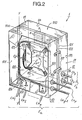
- - la Fig. 2 est une vue en perspective arrière d'une boîte de raccordement et de brassage "direct" selon le premier mode de réalisation ;
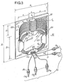
- - la Fig. 3 est une vue en perspective de la face avant du panneau de la boîte de la Fig. 2 ;
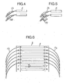
- - les Figs. 4, 5 et 6 montrent différents modes de repérage des fibres optiques ;
- - la Fig. 7 montre schématiquement le raccordement par jarretières de deux ensembles de câbles de fibres optiques ;
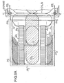
- - les Figs. 8A et 8B sont une vue de face du fond d'une boîte de raccordement et de brassage par jarretières selon le second mode de réalisation dont un panneau est rabattu sur le fond et un autre panneau est sorti par pivotement d'un angle de 180° environ ;
- - la Fig. 9 est une vue de dessus partiellement en coupe de la boîte des Figs. 8A et 8B ; et
- - la Fig. 10 est une vue en coupe le long de la ligne X-X de la Fig. 9 montrant la face interne du fond de la boîte.
- - Fig. 1 schematically shows a connection box of two fiber optic cables without jumpers according to the prior art;
- - Fig. 2 is a rear perspective view of a "direct" connection and patching box according to the first embodiment;
- - Fig. 3 is a perspective view of the front face of the panel of the box of FIG. 2;
- - Figs. 4, 5 and 6 show different methods of locating optical fibers;
- - Fig. 7 schematically shows the connection by garters of two sets of optical fiber cables;
- - Figs. 8A and 8B are a front view of the bottom of a junction box and patching by garters according to the second embodiment of which a panel is folded down on the bottom and another panel is taken out by pivoting by an angle of 180 ° about ;
- - Fig. 9 is a top view partially in section of the box of FIGS. 8A and 8B; and
- - Fig. 10 is a sectional view along line XX of FIG. 9 showing the inner face of the bottom of the box.
La Fig. 1 rappelle schématiquement, selon la technique antérieure, le raccordement de deux câbles Ca et Cb à fibres optiques respectives Fa et Fb par l'intermédiaire de dispositifs de raccordement élémentaires R. Un dispositif de raccordement élémentaire R est appelé dans la suite "raccord" et raccorde l'extrémité d'une fibre optique Fa du premier câble Ca à l'extrémité d'une fibre optique Fb du second câble Cb. La boîte de raccordement BO selon la technique antérieure -dont le contour est représenté par un rectangle en trait fin dans la Fig. 1- est cylindrique. Le fond de la boîte et le couvercle de la boîte forment respectivement des coquilles inférieure et supérieure'dont le plan de jonction est dans l'axe d'alignement longitudinal des extrémités face à face des câbles Ca et Cb.Fig. 1 schematically recalls, according to the prior art, the connection of two cables Ca and Cb with respective optical fibers Fa and Fb by means of elementary connection devices R. An elementary connection device R is hereinafter called "connection" and connects the end of an optical fiber Fa of the first cable Ca to the end of an optical fiber Fb of the second cable Cb. BO connection box according to the prior art -which contour is represented by a rectangle in thin line in FIG. 1- is cylindrical. The bottom of the box and the cover of the box respectively form lower and upper shells, the junction plane of which is in the longitudinal alignment axis of the opposite ends of the cables Ca and Cb.
Les fibres Fa et Fb sont épanouies à partir des extrémités dégainées des câbles Ca et Cb. A l'intérieur de la boîte BO, les moyens pour supporter les raccords R sont par exemple composés de circlips dans chacun desquels s'encastre un raccord. Les raccords sont disposés de part et d'autre le long du petit axe médian, ici vertical, de la boîte BO. Entre l'extrémité de chaque câble Ca, Cb et les raccords R, un espace relativement grand peut être prévu pour loger de grands tronçons des fibres optiques Fa, Fb afin que l'opérateur puisse disposer d'une longueur suffisante pour tirer les fibres lors des raccordements.The fibers Fa and Fb are spread out from the stripped ends of the cables Ca and Cb. Inside the box BO, the means for supporting the fittings R are for example composed of circlips in each of which a fitting is fitted. The connections are arranged on either side along the small median axis, here vertical, of the BO box. Between the end of each cable Ca, Cb and the connections R, a relatively large space can be provided to accommodate large sections of the optical fibers Fa, Fb so that the operator can have a sufficient length to pull the fibers during connections.
On décrit maintenant un premier mode de réalisation d'une boite de raccordement et de brassage selon l'invention qui permet de brasser directement, comme précédemment, les fibres optiques Fa d'un premier ensemble Ea en vue de les raccorder respectivement aux fibres optiques Fb d'un second ensemble Eb, sans l'intermédiaire de jarretières mais plutôt directement par l'intermédiaire de raccords. Pour ce mode de réalisation, les ensembles Ea et Eb de fibres optiques sont composés de plusieurs câbles optiques respectifs Cal, Ca2,... Cap, ...Cap-1, Cap, et Cbl, Cb2, ... Cbp, ... Cbp-1, Cbp où l'indice entier p varie entre 1 et P. Chaque câble Ca , Cb contient M fibres optiques respectives Fa, Fb. Chaque câble peut comprendre par exemple un jonc cylindrique rainuré hélicoidalement dans chaque rainure duquel est disposée une fibre optique, ou un élément porteur cylindrique central autour duquel les fibres optiques sont enrobées, soit dans un composant gélifiant, soit dans des tubes individuels, ou bien.encore, un support plat rainuré. sur lequel sont maintenues coplanairement en nappe ou ruban les fibres optiques. Plusieurs câbles élémentaires tels que Cap ou Cbp peuvent constituer des sous-câbles qui sont enfermés dans l'enveloppe commune. d'un câble composite.We will now describe a first embodiment of a connection and patching box according to the invention which makes it possible to directly brew, as previously, the optical fibers Fa of a first assembly Ea in order to connect them respectively to the optical fibers Fb of a second set Eb, without the intermediary of garters but rather directly by means of fittings. For this embodiment, the sets Ea and Eb of optical fibers are composed of several respective optical cables Ca l , Ca 2 , ... Ca p , ... Ca p-1 , Ca p , and Cb l , Cb 2 , ... Cb p , ... Cb p-1 , Cbp where the whole index p varies between 1 and P. Each cable Ca, Cb contains M respective optical fibers Fa, Fb. Each cable may for example comprise a cylindrical rod helically grooved in each groove of which an optical fiber is arranged, or a central cylindrical support element around which the optical fibers are coated, either in a gelling component, or in individual tubes, or else. again, a flat grooved support. on which are kept coplanar in sheet or ribbon optical fibers. Several elementary cables such as Ca p or Cb p can constitute sub-cables which are enclosed in the common envelope. of a composite cable.
En outre, les raccords ou dispositifs de raccordement élémentaires auxquels fait appel la présente invention sont de préférence des types tels que décrits dans la demande de brevet européen 83401797.2 déposée le 14 septembre 1983. et dans la demande de brevet européen déposée ce jour aux noms des actuelles demanderesses.In addition, the elementary fittings or connection devices to which the present invention relates are preferably types as described in the European patent application 83401797.2 filed on September 14 , 1983. and in the European patent application filed today in the names of the current applicants.
Selon la demande de brevet européen 83401797.2, un raccord des extrémités de deux fibres optiques Fa et Fb comprend un boîtier qui contient un moyen de support de fibres ayant une rainure centrale pour recevoir les extrémités des fibres et des surfaces d'appui des gaines des fibres de part et d'autre de la rainure, et qui contient également des premiers moyens pour presser les extrémités des fibres dans la rainure et des seconds moyens pour presser les gaines des fibres.sur les surfaces d'appui. Les premiers et seconds moyens de pressage sont montés à coulissement dans le boîtier au dessus du moyen de support et sont rappelés contre le moyen de support par des moyens élastiques respectifs.According to European patent application 83401797.2, a connection of the ends of two optical fibers Fa and Fb comprises a housing which contains a fiber support means having a central groove for receiving the ends of the fibers and support surfaces of the fiber sheaths on either side of the groove, and which also contains first means for pressing the ends of the fibers in the groove and second means for pressing the sheaths of the fibers on the bearing surfaces. The first and second pressing means are slidably mounted in the housing above the support means and are urged against the support means by respective elastic means.
Selon la demande de brevet européen déposée ce jour, un raccord des extrémités de deux fibres Fa et Fb comprend une embase ayant une rainure centrale pour recevoir les extrémités des deux fibres, et des moyens de pressage des extrémités des fibres dans la rainure. Les moyens de pressage sont constitués par une plaque-ressort, par exemple en U, dont une première extrémité applique par sa flexion propre les extrémités des fibres dans la rainure et dont la seconde extrémité est solidaire de l'embase.According to the European patent application filed today, a connection of the ends of two fibers Fa and Fb comprises a base having a central groove for receiving the ends of the two fibers, and means for pressing the ends of the fibers in the groove. The pressing means are constituted by a spring plate, for example in a U, of which a first end applies by its own bending the ends of the fibers in the groove and whose second end is integral with the base.
Ces types de raccord présentent principalement les avantages suivants :
- - bonne qualité de transmission optique au niveau de la jonction des extrémités des fibres optiques et fiabilité élevée malgré la simplicité relative de leur structure et de leur manipulation ;
- - la réalisation d'un raccordement ne fait pas appel à une main d'oeuvre différente de celle employée pour les épissures de conducteurs de câbles électriques, et est très rapide du fait qu'aucun démontage des pièces composant le raccord n'est nécessaire ; et corollairement, simplicité de l'outillage nécessaire aux raccordement et coût du raccordement réduit ;
- - réversibilité de la connexion optique, c'est-à-dire possibilité de déconnecter et de connecter à nouveau des fibres optiques un grand nombre de fois au moyen du même raccord sans aucun démontage et remplacement des pièces du raccord ;
- - la forme parallélépipédique mince des raccords permet de réaliser des empilages de très faibles encombrements dans lesquels l'épaisseur de l'espace imparti à un raccord est de l'ordre de 4 à 5 mm.
- - good optical transmission quality at the junction of the ends of the optical fibers and high reliability despite the relative simplicity of their structure and handling;
- - Making a connection does not call for a different workforce than that used for splicing electrical cable conductors, and is very rapid because no disassembly of the parts making up the connection is necessary; and as a corollary, simplicity of the tools necessary for connection and reduced connection cost;
- - reversibility of the optical connection, that is to say the possibility of disconnecting and reconnecting optical fibers a large number of times by means of the same fitting without any dismantling and replacement of the pieces of the fitting;
- - The slim parallelepiped shape of the fittings makes it possible to produce stacks of very small dimensions in which the thickness of the space allocated to a fitting is of the order of 4 to 5 mm.
Concernant le dernier avantage, les raccords parallélépipédiques minces sont enfichés entre des cloisons parallèles, de préférence amovibles, qui sont fixés sur un support plan S formant un barrette compacte parallélépipédique. Le support S comporte entre deux cloisons voisines des pattes, languettes, bossages, ou analogues flexibles pour verrouiller un raccord,.par exemple au moyen de deux encoches latérales du raccord. Un tel empilage de raccord présente ainsi un encombrement réduit et permet, le cas échéant, de raccorder des fibres optiques sans aucun retrait des raccords du fait que des extrémités des moyens de pressage des raccords sont accessibles par le dessus de la barrette S au moyen d'un outil de maniement simple.Regarding the last advantage, the thin parallelepipedic connections are inserted between parallel partitions, preferably removable, which are fixed on a flat support S forming a compact parallelepiped strip. The support S comprises, between two adjacent partitions, flexible lugs, tongues, bosses, or the like for locking a connection, for example by means of two lateral notches of the connection. Such a connector stack thus has a reduced overall size and makes it possible, if necessary, to connect optical fibers without any withdrawal of the connectors because the ends of the means for pressing the connectors are accessible from above the bar S by means of '' a simple handling tool.
Une boîte de raccordement et de brassage direct 1 selon l'invention est montrée à la Fig. 2. On y retrouve des premiers câbles Cal à Cap du premier ensemble Ea, des second câbles Cb1 à Cbp du second ensemble Eb, des raccords R et une barrette S tels que décrits ci-dessus.A direct connection and
La boîte 1 est parallélépipédique. Elle comprend un premier réceptacle 10, un second réceptacle 11 et un panneau amovible 12. Le premier réceptacle 10 et le second réceptacle 11 forment le fond et le couvercle de la boîte 1 et sont superposables. Le panneau 12 forme une cloison rectangulaire entre le fond et le couvercle et partage ainsi la boîte en un premier compartiment arrière parallélépipédique 100 qui est délimité par.les parois du fond 10, et en un second compartiment avant parallélépipédique 110 qui est délimité par les parois du couvercle 11. Le panneau 12 peut être fixé sur les chants avant du fond ou sur les chants arrière du couvercle. De préférence, le panneau est monté sur le fond afin de rendre plus accessible les raccords R de la barrette S contenue dans le compartiment avant 110. Le panneau 12 peut être fixé aux chants avant du fond par vissage, encliquetage ou analogue ou de préférence peut être monté à pivotement autour de l'axe d'articulation Y'Y d'une charnière le long du bord avant d'une paroi du fond 10, tel que le côté 101 montré à la Fig. 2. Dans ce dernier cas, le panneau 12 est pivoté vers l'extérieur du fond 10 autour de l'axe Y'Y pour lover les fibres optiques Fa et ensuite est rabattu contre des butées aux voisinages des bords des trois autres côtés 102, 103 et 104 du fond 10.
Les premiers câbles Ca1 à Cap pénètrent dans les compartiment arrière 100 à travers des trous 105 qui sont prévus dans au moins l'un des côtés, tel que 102,du fond 10 adjacent au côté 101 supportant la charnière du panneau 12, et de préférence, dans les trois côtés 102, 103 et 104. Les trous 105 sont éventuellement équipés chacun d'un presse-étoupe 106, par exemple du genre manchon en caoutchouc, dans lequel s'enfile une extrémité gainée du câble respectif Ca et qui rend étanche la liaison entre le câble et la boîte. Après dégainage des câbles Ca à Cap sur une grande longueur à partir des faces internes des côtés du fond 10, et éventuellement tronçonnage des éléments porteurs des câbles s'ils existent devant lesdites faces internes, les fibres optiques Fa des câbles Ca1 à Cap sont dégagées et sont ensuite réunies en faisceau.The first cables Ca 1 to Ca p enter the
Les fibres Fa sortant des câbles Cal à Cap sont glissées dans des moyens de guidage rectiligne 120-121 qui sont parallèles et adjacents à l'axe de pivotement Y'Y du panneau 12 et qui sont fixés sur la face arrière 122 du panneau 12. Les moyens de guidage rectiligne peuvent être constitués par au moins deux tronçons de tube ou deux anneaux de préférence fendus 120 et 121 ayant leur axe aligné et parallèle à l'axe Y'Y. La distance entre les anneaux extrêmes 120 et 121 montrés à la Fig. 2 peut être égale à environ 400 fois le diamètre nominal d'une fibre optique afin que les fibres optiques Fa puissent travailler en flexion- torsion.The fibers Fa leaving the cables Ca l to Ca p are slid into rectilinear guide means 120-121 which are parallel and adjacent to the pivot axis Y'Y of the
Après le guidage rectiligne dans les moyens de guidage 120-121, ici de bas en haut, le faisceau des fibres optiques Fa est ensuite lové "en galette", c'est-à-dire à plat, contre la face arrière 122 du panneau 12 en plusieurs boucles d'aisance Ba pratiquement circulaires et superposées. Les boucles Ba permettent à l'opérateur de disposer de longueurs suffisantes des fibres Fa pour préparer les extrémités des fibres et les introduire dans les raccords R. Les boucles Ba constituent des réserves de fibres en cas d'incident entraînant l'obligation de refaire des raccordements ou de couper à nouveau les extrémités de fibres. Afin de lover convenablement les fibres Fa sans embrouille, c'est-à-dire de ne point entremêler les fibres et de les maintenir en un faisceau curviligne ayant un rayon de courbure minimum de r = 50 mm, des gouttières coplanaires 123 à section transversale en U sont prévues sur la face arrière 122 du panneau 12. Par exemple, comme montré à la Fig. 2, quatre gouttières 123 sont disposées le long des côtés d'un carré qui enferme un cercle d'un rayon supérieur à r. Les gouttières peuvent être disposées selon une configuration autre que carrée, telle que rectangulaire, ovale, etc. Les branches libres des gouttières 123 vers l'intérieur du compartiment arrière 100 sont prôfilées en trapèze isocèle et sont disjointes afin de permettre l'insertion des fibres Fa et leur maintien en boucles d'aisance Ba. A la place des gouttière ou conjointement à celles-ci peuvent être utilisées des attaches rapides en forme d'anneau qui entourent le faisceau des fibres Fa et dont les tiges avant sont encliquetées dans des trous répartis circulairement sur la face arrière 122 du panneau 12. Dans la Fig. 2, on n'a représenté que quelques boucles d'aisance Ba du faisceau des fibres Fa afin de ne pas surcharger le dessin, bien qu'en pratique, une dizaine de boucles d'aisance puisse être formée pour chaque fibre optique en tournant suivant le sens des aiguilles d'une montre.After the rectilinear guide in the guide means 120-121, here from bottom to top, the bundle of optical fibers Fa is then coiled "in wafer", that is to say flat, against the
Les fibres optiques Fa sont ensuite tirées, ici- à partir de la gouttière inférieure 123, à travers un orifice oblong 124 du panneau 12 entre les moyens de guidage 120-121 et la surface de lovage arrière définie par les boucles d'aisance Ba. L'orifice 124 est par exemple pratiqué à mi-hauteur entre les anneaux alignés 120 et 121 et le fond de la gouttière verticale de gauche 123, comme montré à la Fig. 2. Le faisceau des fibres Fa débouche ainsi sur la face avant 125 du panneau 12 avec une longueur suffisante pour permettre l'insertion des fibres Fa dans les raccords R. Après les opérations précédentes, le panneau 12 pivote autour de l'axe Y'Y et est rabattu sur la face avant du fond 10 pour fermer le compartiment arrière 100 et y être maintenu à cette position par un dispositif de verrouillage adéquat. Le dispositif de verrouillage peut être constitué par un ou plusieurs loqueteaux qui sont fixés sur le chant avant du fond 10 recevant en butée le chant libre du panneau parallèle et opposé à l'axe Y'Y. Deux tels loqueteaux sont montrés schématiquement en 107 dans la Fig. 2.The optical fibers Fa are then drawn, here- from the
Sur la face avant 125 du panneau 12 montrée à la Fig. 3, on retrouve en partie supérieure la pile de raccords R à RMP encastrés entre les cloisons de la barrette S. La barrette S est fixée verticalement sur la face avant 125 par exemple par vis. Comme déjà dit, les raccords R sont conformes à l'un de ceux décrits dans la demande de brevet européen 83401797.2 et la demande de brevet européen déposée ce jour. Les grandes faces rectangulaires des raccords R sont disposées horizontalement. Les chants verticaux des raccords R donnant accès aux moyens de pressage en vue de dégager les rainures et d'y enfiler les extrémités des fibres sont en face de la grande face interne du couvercle I1.On the
Les extrémités des tronçons extrêmes des fibres Fa débouchant de l'orifice 124 sont enfilées dans une première moitié des rainures des raccords R, à raison d'une fibre Fa par raccord. Le nombre de raccords R est égal ou supérieur au nombre total M × P des fibres contenues dans un ensemble Ea, Eb. De préférence, les premiers câbles Ca constituent des câbles "précâblés", ce qui signifie qu'à chaque fibre Fa du premier ensemble Ea est assigné définitivement un raccord R, le brassage des raccordements s'effectuant par le choix variable d'un raccord R pour chacune des fibres optiques Fb du second ensemble Eb. Afin de protéger les fibres "précâblées" Fa dans le compartiment avant 110, des grilles de protection 117 recouvrent les tronçons extrêmes des fibres Fa après insertion dans les raccords R et sont fixées à la face avant 125 du panneau. Ainsi, après précâblage des fibres Fa, toutes les opérations, notamment relatives au brassage, s'effectuent dans le compartiment avant 110, le panneau rabattu 12 contre le fond 10 protégeant les fibres Fa.The ends of the end sections of the fibers Fa emerging from the
L'opérateur procède ensuite au lovage à plat et à l'insertion des fibres Fb dans les raccords R. En premier lieu, les seconds câbles Cb1 à Cbp sont passés dans des trous 115 qui sont prévus dans au moins l'un des côtés 111, 112, 113 et 114 du couvercle 11 et qui sont éventuellement équipés chacun d'un presse-étoupe 116, comme montré à la Fig. 2. Après épanouissement des fibres Fb des seconds câbles dans le compartiment avant 110, d'une manière analogue à celui des fibres Fa, les fibres Fb sont réunies en un faisceau qui est lové à plat en des boucles d'aisance pratiquement circulaires et superposées Bb suivant le sens contraire de celui des boucles Ba des fibres Fa qui sont lovées à contre, vues de la face avant 125 du panneau 12. Les boucles Bb permettent de disposer de surlongueurs suffisantes de fibres Fb pour effectuer commodément la préparation des extrémités des fibres Fb et leur insertion dans les moitiés -à gauche dans la Fig. 3- des rainures des raccords, et également permettent de palier aux éventuels incidents provoquant une reprise de raccordement et de réaliser le brassage. Le brassage consiste par exemple à retirer l'extrémité d'une fibre Fb qui est initialemen insérée dans un raccord tel que R1, et à l'insérer dans un autre raccord tel que Rp (Fig. 3).The operator then coils flat and inserts the fibers Fb into the fittings R. First, the second cables Cb 1 to Cbp are passed through holes 115 which are provided in at least one of the
L'aire de lovage des fibres Fb est délimitée en partie basse de la face avant 125 du panneau 12, sous la barrette S, par quatre gouttières coplanaires 126 qui ont une disposition mutuelle en carré analogue à celle des gouttières 123 sur la face arrière 122 du panneau. Chaque gouttière 126 a également une section en U dont la grande branche avant libre est profilée en trapèze isocèle et dont la petite branche rectangulaire est fixée sur la face avant 125 du panneau 12 dans l'aire de lovage des fibres Fb. Comme montré à la Fig. 3, les fibres Fb sortant des extrémités des seconds câbles Cbl à CbP au niveau des presse-étoupes 116 dans les côtés du couvercle 11 pénètrent dans l'aire de lovage à travers des fentes verticales 127 de la branche trapézoidale de la gouttière horizontale inférieure 126, puis sont lovées dans les quatre gouttières 126 en plusieurs boucles d'aisance Bb et enfin sortent de l'extrémité supérieure de la gouttière verticale de gauche 126 en vue de l'introduction des extrémités des fibres Fb dans les moitiés de gauche des rainures des raccords R.The coiling area of the fibers Fb is delimited in the lower part of the
Le repérage des fibres Fa, Fb peut être réalisé au moyen de bagues 118 montrée à la Fig. 4, ou au moyen de drapeaux 119 montrés à la Fig. 5 enfilés chacun autour de l'extrémité gainée d'une fibre Fa, Fb et comportant un numéro respectif, ou bien encore au-moyen d'un numérotage à proximité des deux extrémités des raccords R dans la barrette S comme montré a la Fig. 6. Lorsque toutes les extrémités des fibres Fb sont insérées dans les raccords respectifs R, le couvercle 11 est superposé au fond 10 et fixé sur celui-ci par vissage, encliquetage ou analogue.The identification of the fibers Fa, Fb can be carried out by means of rings 118 shown in FIG. 4, or by means of
L'un des avantages de l'organisation interne des fibres dans la boîte de raccordement et de brassage direct 1 est le faible encombrement de la boîte. Pour fixer les idées en référence à la Fig. 3, les dimensions en hauteur A et largeur B d'une boîte, c'est-à-dire du panneau 12 et des grandes faces du fond 10 et du couvercle 11, peuvent être calculées comme suit pour un raccordement des fibres deux à deux de deux ensembles Ea et Eb contenant chacun P = 5 câbles à M = 10 fibres chacun :
- - largeur de la barrette : L = 40 mm ;
- - hauteur de l'intervalle disponible pour un raccord I = 5 mm (Fig. 6) ; ;
- - hauteur (longueur) de la barrette contenant M.P = 50 raccords : H = I (M.P + 1), soit H = 5 (10.5 + 1) = 255 mm ;
- - tolérance sur la hauteur A : ε = 10 mm ;
- - hauteur A de la boîte :
- A = (H + 2r) + E, soit A = 255 + 100 + 10 = 365 mm ;
- - tolérance sur la largeur B : 3 ε = 30 mm ;
- - largeur B de la boîte :
- B = (L + 2r) + 3 ε, soit B = 40 + 100 + 30 = 170 mm.
- - width of the bar: L = 40 mm;
- - height of the gap available for a fitting I = 5 mm (Fig. 6); ;
- - height (length) of the bar containing MP = 50 connections: H = I (MP + 1), ie H = 5 (10.5 + 1) = 255 mm;
- - tolerance on height A: ε = 10 mm;
- - height A of the box:
- A = (H + 2r) + E , that is A = 255 + 100 + 10 = 365 mm;
- - tolerance on width B: 3 ε = 30 mm;
- - width B of the box:
- B = (L + 2r) + 3 ε, i.e. B = 40 + 100 + 30 = 170 mm.
Le second mode de réalisation d'une boîte de. raccordement et de brassage selon l'invention a trait à un brassage entre plusieurs câbles Ca et Cb, comme montré schématiquement à la Fig. 7. Les fibres Fa, Fb de chaque câble Ca, Cb sont introduites respectivement dans des raccords Ra, Rb d'une barrette respective Sa, Sb. Chaque raccord Ra est ensuite relié à l'un des raccords Rb par une jarretière J qui est constituée par une fibre optique et qui est disposée dans l'espace compris entre les deux barrettes parallèles Sa et Sb.The second embodiment of a box. Connection and patching according to the invention relates to patching between several cables Ca and Cb, as shown diagrammatically in FIG. 7. The fibers Fa, Fb of each cable Ca, Cb are introduced respectively into connections Ra, Rb of a respective bar Sa, Sb. Each connection Ra is then connected to one of the connections Rb by a jumper J which is constituted by an optical fiber and which is arranged in the space between the two parallel bars Sa and Sb.
Le procédé de brassage par jarretières double le nombre de raccordements à effectuer et, par conséquent, double sensiblement la durée et le coût de l'opération pour un nombre de raccordements égal à celui du procédé à brassage "direct" (Fig. 1). Cependant, le brassage par jarretières permet avantageusement de précâbler définitivement les fibres Fa et Fb dans les raccords respectifs Ra et Rb, c'est-à-dire d'assigner définitivement chaque fibre entrant dans la boîte à un raccord. Le raccordement d'une fibre Fa d'un premier câble Ca à une fibre Fb d'un second câble Cb est réalisé séparément par une jarretière J et à la demande. Les jarretières sont plus faciles à manipuler et à ranger dans des aires de lovage que les fibrés des câbles. Sans aucune intervention ultérieure sur la disposition relative des fibres précâblées Fa, Fb, tout raccordement entre une fibre quelconque Fa et une fibre quelconque Fb peut être effectué soit en réutilisant une jarretière déjà dans la boîte, soit en introduisant une nouvelle jarretière ou une jarretière libre et en déconnectant les extrémités des jarretières initiales reliées aux fibres à raccorder.The patching method with garters doubles the number of connections to be made and, therefore, significantly doubles the duration and cost of the operation for a number of connections equal to that of the "direct" patching process (Fig. 1). However, the stirring by garters advantageously makes it possible to definitively prewire the fibers Fa and Fb in the respective connectors Ra and Rb, that is to say to permanently assign each fiber entering the box to a connector. The connection of a fiber Fa of a first cable Ca to a fiber Fb of a second cable Cb is carried out separately by a jumper J and on request. Garters are easier to handle and store in coiling areas than cable bundles. Without any subsequent intervention on the relative arrangement of the prewired fibers Fa, Fb, any connection between any fiber Fa and any fiber Fb can be carried out either by reusing a jumper already in the box, or by introducing a new jumper or a free jumper and by disconnecting the ends of the initial jumpers connected to the fibers to be connected.
La boîte de raccordement et de brassage par jarretières 2 montrée aux Figs. 8 à 10 est prévue pour raccorder une fibre Fa, Fb d'un quelconque câble Ca, Cb parmi une pluralité de câble à une fibre optique Fa, Fb d'un autre câble de cette pluralité de câbles. Elle est également parallélépipédique et est constituée par un couvercle 20 et un fond 21. La boîte renferme dans un premier compartiment 200 plusieurs panneaux montés à pivotement autour d'un axe vertical Y'Y solidaire du fond 21 et disposé dans un coin vertical, ici à gauche, du fond. Dans les Figs. 8 à 10, on a supposé que la boite 2 renferme deux panneaux amovibles 221 et 222 Chaque panneau 221, 222 comporte deux bras 2281, 2282 qui sont articules autour de l'axe Y'Y sans translation le long de cet axe et qui sont coudés de telle sorte que les panneaux puissent être disposés parallèlement aux grandes faces du couvercle 20 et du fond 21 lorsque la boîte est fermée. Lorsque la boîte est ouverte, chaque panneau peut pivoter de 180° environ vers l'extérieur du fond 21.The connection and patching box with jumpers 2 shown in Figs. 8 to 10 is provided for connecting a fiber Fa, Fb of any cable Ca, Cb among a plurality of cables to an optical fiber Fa, Fb of another cable of this plurality of cables. It is also parallelepipedic and is constituted by a
Sur l'une des grandes faces rectangulaires verticales 2221, 2222 de chaque panneau 221, 222 sont fixées parallèlement deux barrettes horizontales Sa1 et Sb1, Sa2 et Sb2, de raccords Ra1 et Rb1, Ra2 et Rb2. Entre les deux barrettes sur un même panneau est prévue une aire de lovage 2231, 2232 de jarretières. J1, J2 pour raccorder chacune un raccord de l'une des deux barrettes à un raccord de l'autre barrette. De préférence, comme montré à la Fig.9, des panneaux tels que 221 et 222 aux extrémités de l'empilement des panneaux ont des grandes faces 2251 et 2252 respectivement en vis-à-vis des faces internes du couvercle 20 et du.fond 21 qui ne supportent aucune barrette de raccords.On one of the large vertical rectangular faces 222 1 , 222 2 of each panel 22 1 , 22 2 are fixed in parallel two horizontal bars Sa 1 and Sb 1 , Sa 2 and Sb 2 , of connections Ra 1 and Rb 1 , Ra 2 and Rb 2 . Between the two bars on the same panel is provided a coiling area 223 1 , 223 2 of garters. J 1 , J 2 to each connect a connector of one of the two bars to a connector of the other bar. Preferably, as shown in FIG. 9, panels such as 22 1 and 22 2 at the ends of the stack of panels have
Sur les aires de lovage 2231, 2232 des jarretières J1, J2 sont prévues un ou plusieurs ensembles de gouttières (non représentés) tels que ceux montrés aux Figs. 2 et 3, afin de réaliser les boucles d'aisance des jarretières ayant un rayon au moins égal à r = 50 mm. En effet, la longueur d'une jarretière est variable et dépend de son chemin suivi entre deux raccords à relier qui peuvent être soit sur un même panneau, soit sur deux panneaux respectifs parmi la pluralité de panneaux. Lorsqu'une jarretière relie deux raccords sur des panneaux différents, la jarretière sortant de l'aire de lovage de l'un des panneaux chemine dans des moyens de guidage 220-221, à tubes ou à anneaux, qui sont pour partie solidaires de l'un des panneaux, pour partie solidaires du fond 21 et pour partie solidaires de l'autre panneau, comme montré aux Figs..8A et 8B. Ces moyens de guidage permettent un passage rectiligne des jarretières le long de l'axe vertical Y'Y de pivotement des panneaux. Les moyens de guidage servent également à acheminer vers les raccords respectifs les tronçons extrêmes des fibres optiques Fa et Fb qui peuvent être protégés par des grilles 2171 et 2172 montrées aux Figs. 8A et 8B.On the coiling areas 223 1 , 223 2 of the garters J 1 , J2 are provided one or more sets of gutters (not shown) such as those shown in Figs. 2 and 3, in order to make the loops of jumpers with a radius at least equal to r = 50 mm. Indeed, the length of a garter is variable and depends on its path followed between two connections to be connected which can be either on the same panel, or on two respective panels among the plurality of panels. When a jumper connects two fittings on different panels, the jumper leaving the coiling area of one of the panels travels in guide means 220-221, with tubes or rings, which are partly integral of one of the panels, partly secured to the bottom 21 and partly secured to the other panel, as shown in Figs..8A and 8B. These guide means allow a rectilinear passage of the garters along the vertical axis Y'Y of pivoting of the panels. The guide means also serve to convey to the respective fittings the end sections of the optical fibers Fa and Fb which can be protected by grids 217 1 and 217 2 shown in Figs. 8A and 8B.
Comme montré à la Fig. 9, les panneaux rabattus vers le fond 21 laissent un compartiment libre 210 entre la grande face interne du fond 21 et le dernier panneau tel que 222 en vis-à-vis de celle-ci. Le compartiment 210 montré à la Fig. 10 est disponible pour le lovage des fibres entrantes Fa et Fb et accessible par pivotement des panneaux vers l'extérieur du fond 21. Les câbles Ca, Cb à raccorder pénètrent à travers des trous 215a, 215b équipés de presse-étoupes 216a, 216b et pratiqués dans les quatre côtés du fond 21. Dès leur entrée dans le fond, les câbles sont dégainés, mais leur élément porteur flexible, s'il existe, n'est pas scié immédiatement. Les éléments porteurs flexibles avec leurs fibres sont lovés à plat contre la grande face interne du fond 21 en des boucles d'aisance Ba, Bb dont le rayon est au moins égal à r = 50 mm et qui sont maintenues par des ensembles de gouttières (non représentés) analogues à ceux montrés aux Figs. 2 et 3. les éléments porteurs ne sont sciés qu'en sortie des ensembles de gouttières où les fibres Fa et Fb sont acheminées par passage rectiligne dans les moyens de guidage 220-221 le long de l'axe de pivotement Y'Y, vers les raccords respectifs sur les panneaux.As shown in Fig. 9, the panels folded down towards the bottom 21 leave a
Certains câbles, tels que C'a et C'b, n'ont pas besoin d'être brassés, mais peuvent être seulement raccordés deux à deux. Dans ce cas, comme montré au centre de la Fig. 10, la face interne du fond 21 supporte une barrette S de raccord pour un brassage direct ainsi que des gouttières (non représentées) pour lover les fibres de ces câbles en boucles d'aisance ayant un rayon au moins égal à r = 50-mm.Some cables, such as C'a and C'b, do not need to be patched, but can only be connected two by two. In this case, as shown in the center of Fig. 10, the internal face of the bottom 21 supports a connecting bar S for direct mixing as well as gutters (not shown) for coiling the fibers of these cables in ease loops having a radius at least equal to r = 50-mm .
On notera que dans les Figs. 8 à 10 n'ont pas été détaillés les moyens auxiliaires pour guider, lover et repérer les fibres et jarretières afin de ne pas surcharger les figures. Ces moyens sont pratiquement analogues à ceux décrits pour la boîte de brassage direct 1 qui peut également contenir plusieurs panneaux qui pivotent autour du même axe et qui supportent chacun des moyens de guidage et de lovage et une barrette de raccord pour le brassage direct des fibres de deux ensembles respectifs.Note that in Figs. 8 to 10 have not been detailed the auxiliary means for guiding, coiling and locating the fibers and garters so as not to overload the figures. These means are practically analogous to those described for the
La barrette de raccord sur le panneau 12 de la boîte de brassage direct 1 peut être remplacée par deux barrettes parallèles de raccord en vue d'effectuer un brassage par jarretières. Dans ce cas, chaque raccord d'une barrette permet de relier une fibre optique de l'ensemble respectif Ea, Eb à une jarretière J dont l'autre, extrémité est insérée dans un raccord de l'autre barrette. La face avant 125 du panneau 12 (Fig. 3) est analogue à la face 2221, 2222 d'un panneau 221, 222 (Figs. 8 et 9) et supporte des pièces coplanaires en forme de gouttière ou d'anneau qui sont équiréparties autour d'un ou de plusieurs cercles et qui contiennent les boucles des jarretières lovées à plat entre les deux barrettes.The connection bar on the
Claims (28)
Applications Claiming Priority (2)
| Application Number | Priority Date | Filing Date | Title |
|---|---|---|---|
| FR8300075A FR2538918A1 (en) | 1983-01-05 | 1983-01-05 | FIBER OPTIC CONNECTION AND BREWING BOX |
| FR8300075 | 1983-04-21 |
Publications (2)
| Publication Number | Publication Date |
|---|---|
| EP0116480A1 true EP0116480A1 (en) | 1984-08-22 |
| EP0116480B1 EP0116480B1 (en) | 1987-05-20 |
Family
ID=9284675
Family Applications (1)
| Application Number | Title | Priority Date | Filing Date |
|---|---|---|---|
| EP84400006A Expired EP0116480B1 (en) | 1983-01-05 | 1984-01-04 | Connecting and mixing box for optical fibres |
Country Status (5)
| Country | Link |
|---|---|
| US (1) | US4717231A (en) |
| EP (1) | EP0116480B1 (en) |
| CA (1) | CA1250464A (en) |
| DE (1) | DE3463851D1 (en) |
| FR (1) | FR2538918A1 (en) |
Cited By (22)
| Publication number | Priority date | Publication date | Assignee | Title |
|---|---|---|---|---|
| FR2561788A1 (en) * | 1984-03-26 | 1985-09-27 | Silec Liaisons Elec | Cassettes for optical fibres and connection box using such cassettes |
| EP0178179A2 (en) * | 1984-10-11 | 1986-04-16 | Reliance Electric Company | Handling and storing cable spliced ends of optical fibers |
| GB2165661A (en) * | 1984-10-15 | 1986-04-16 | Telephone Cables Ltd | Optical fibre junction box |
| GB2166262A (en) * | 1984-10-25 | 1986-04-30 | Northern Telecom Ltd | Optical cable terminating cabinet |
| FR2575020A1 (en) * | 1984-12-14 | 1986-06-20 | Nozick Jacques | DISTRIBUTOR FOR OPTICAL CABLES |
| GB2169093A (en) * | 1984-12-31 | 1986-07-02 | Ian Mackinlay | Optical fibre splice housing |
| FR2577688A1 (en) * | 1985-02-21 | 1986-08-22 | Lignes Telegraph Telephon | Fibre-optic distribution frame |
| FR2579330A1 (en) * | 1985-03-19 | 1986-09-26 | Lignes Telegraph Telephon | Device for connecting and protecting splices for fibre-optic line cables and method of implementation |
| EP0204581A2 (en) * | 1985-06-07 | 1986-12-10 | Telephone Cables Limited | Splice storage housing |
| FR2585518A1 (en) * | 1985-07-23 | 1987-01-30 | Lignes Telegraph Telephon | CONNECTING DEVICE |
| DE3530344A1 (en) * | 1985-08-24 | 1987-02-26 | Rose Walter Gmbh & Co Kg | House connection box for optical waveguides |
| FR2586822A1 (en) * | 1985-09-05 | 1987-03-06 | Lignes Telegraph Telephon | Fibre-optic reserve (overlength) device which can be used especially in a fibre-optic distribution frame |
| FR2586827A1 (en) * | 1985-09-05 | 1987-03-06 | Lignes Telegraph Telephon | Device for rapidly earthing a cable, such as an optical cable |
| EP0215520A2 (en) * | 1985-09-11 | 1987-03-25 | Philips Patentverwaltung GmbH | Process for establishing a connection between two optical fibres, and arrangement to perform this process |
| EP0215668A2 (en) * | 1985-09-17 | 1987-03-25 | Adc Telecommunications, Inc. | Optical fiber distribution apparatus |
| US4792203A (en) * | 1985-09-17 | 1988-12-20 | Adc Telecommunications, Inc. | Optical fiber distribution apparatus |
| EP0369524A2 (en) * | 1988-11-12 | 1990-05-23 | Philips Patentverwaltung GmbH | Distribution rack for making freely selectable optical connections |
| AU607619B2 (en) * | 1988-06-29 | 1991-03-07 | American Telephone And Telegraph Company | An opto-electronic interface arrangement |
| GR1001278B (en) * | 1991-05-10 | 1993-07-30 | Kabelmetal Electro Gmbh | Cable end arrangement for a cable conductor of light waves. |
| EP0715386A1 (en) * | 1994-11-30 | 1996-06-05 | Alcatel SEL Aktiengesellschaft | Enclosure for electrical or electronic components |
| EP0744640A1 (en) * | 1995-05-24 | 1996-11-27 | Alcatel Cable Interface | Connection box for optical fibres |
| WO2016128083A1 (en) * | 2015-02-09 | 2016-08-18 | Genexis Holding B.V. | Fiber connection assembly |
Families Citing this family (103)
| Publication number | Priority date | Publication date | Assignee | Title |
|---|---|---|---|---|
| US5133038A (en) * | 1980-04-17 | 1992-07-21 | Reliance Comm/Tec. Corporation | Fiber optic splice case |
| US4627686A (en) * | 1984-08-10 | 1986-12-09 | Siecor Corporation | Splicing tray for optical fibers |
| US5093886A (en) * | 1984-10-15 | 1992-03-03 | Telephone Cables Limited | Optical communication system |
| FR2590371B1 (en) * | 1985-11-18 | 1988-09-16 | Cit Alcatel | OPTICAL CABLES HEAD CHASSIS |
| FR2598822B1 (en) * | 1986-05-16 | 1988-08-26 | Telecommunications Sa | DISTRIBUTION EQUIPMENT AND CONNECTION OF OPTICAL FIBERS. |
| US4884863A (en) * | 1989-03-06 | 1989-12-05 | Siecor Corporation | Optical fiber splicing enclosure for installation in pedestals |
| US4900123A (en) * | 1988-08-29 | 1990-02-13 | Gte Products Corporation | 1550 nm fiber distribution panel |
| US4948222A (en) * | 1988-12-05 | 1990-08-14 | Aster Corporation | Optical fiber unit assembly package |
| US5071211A (en) * | 1988-12-20 | 1991-12-10 | Northern Telecom Limited | Connector holders and distribution frame and connector holder assemblies for optical cable |
| US4909583A (en) * | 1989-01-05 | 1990-03-20 | Hughes Aircraft Company | Method and apparatus for preserving modes in fiber optic connections requiring angular translation |
| US5255337A (en) * | 1989-01-17 | 1993-10-19 | N.V. Raychem S.A. | Splice case for optical fibre cable |
| US5029958A (en) * | 1989-04-28 | 1991-07-09 | Scientific-Atlanta, Inc. | Optical fiber enclosure for optoelectronic converter |
| US5013121A (en) * | 1989-06-29 | 1991-05-07 | Anton Mark A | Optical fiber storage container |
| US5208894A (en) * | 1990-07-16 | 1993-05-04 | Adc Telecommunications, Inc. | Fiber optic splice cabinet |
| US5109467A (en) * | 1991-02-27 | 1992-04-28 | Keptel, Inc. | Interconnect cabinet for optical fibers |
| US5199095A (en) * | 1991-05-06 | 1993-03-30 | Computer Crafts, Inc. | Fiberoptic cable feedthrough fastener and method for forming same |
| DE4119829A1 (en) * | 1991-06-15 | 1992-12-17 | Rose Walter Gmbh & Co Kg | DEVICE FOR DIVIDING LIGHTWAVE GUIDE CABLES OR - Veins |
| US5303320A (en) * | 1992-09-21 | 1994-04-12 | David B. Duffie | Fiber optic signal distribution system and raceway and panel associated therewith |
| CA2081608C (en) * | 1992-10-28 | 1998-05-05 | Joseph Octave Regis Morin | Distribution frame and optical connector holder combination |
| CH688112A5 (en) * | 1993-03-23 | 1997-05-15 | Reichle & De Massari Fa | Cartridge assembly for connecting and branching of optical waveguides of the telecommunications and data communications. |
| US5546495A (en) * | 1993-04-16 | 1996-08-13 | The Whitaker Corporation | Splice tray rack and cabinet for fiber optic cables |
| TW232757B (en) | 1994-01-21 | 1994-10-21 | Adc Telecommunications Inc | High-density fiber distribution frame |
| GB2291209B (en) * | 1994-06-20 | 1998-04-01 | Pirelli General Plc | Optical fibre organiser having guiding tube for optical fibre |
| US5535298A (en) * | 1995-01-30 | 1996-07-09 | The Whitaker Corporation | Pedestal for fiber optic cable |
| US5724469A (en) * | 1996-01-26 | 1998-03-03 | Ortronics, Inc. | Adjustable fiber storage plate |
| US5708751A (en) * | 1996-04-24 | 1998-01-13 | Tii Industries, Inc. | Optical fiber enclosure system |
| WO1998041891A1 (en) * | 1997-03-17 | 1998-09-24 | Tii Industries, Inc. | Fiber optic cable bend radius controller |
| US5892877A (en) * | 1997-06-30 | 1999-04-06 | Tii Industries, Inc. | Optical fiber strain relief system |
| US5915055A (en) * | 1997-06-30 | 1999-06-22 | Siecor Corporation | Method and apparatus for connectorizing fiber optic cable |
| DE29714733U1 (en) * | 1997-08-16 | 1997-10-09 | Hirschmann Richard Gmbh Co | Device unit |
| US5946440A (en) * | 1997-11-17 | 1999-08-31 | Adc Telecommunications, Inc. | Optical fiber cable management device |
| US6160946A (en) | 1998-07-27 | 2000-12-12 | Adc Telecommunications, Inc. | Outside plant fiber distribution apparatus and method |
| US6201919B1 (en) | 1998-12-16 | 2001-03-13 | Adc Telecommunications, Inc | Fiber distribution frame |
| GB9928201D0 (en) * | 1999-11-30 | 2000-01-26 | Raychem Sa Nv | Optical fibre connection unit |
| US6352374B1 (en) * | 2000-06-08 | 2002-03-05 | Amphenol Corporation | Fiber optic connector device |
| US6379166B1 (en) | 2000-06-26 | 2002-04-30 | Randl Industries, Inc. | Fiber optic cable outlet box |
| US6408124B1 (en) | 2000-09-21 | 2002-06-18 | Adc Telecommunications, Inc. | Cable storage cartridge |
| US6625374B2 (en) | 2001-03-07 | 2003-09-23 | Adc Telecommunications, Inc. | Cable storage spool |
| US6522824B2 (en) * | 2001-03-26 | 2003-02-18 | Corning Cable Systems Llc | Corner wall-mount fiber optic connector housing |
| US6487357B1 (en) * | 2001-05-31 | 2002-11-26 | Lucent Technologies Inc. | Strain relief device with bend limiter and slack storage |
| US6819857B2 (en) | 2001-10-12 | 2004-11-16 | Adc Telecommunications, Inc. | Rotating vertical fiber tray and methods |
| US6591051B2 (en) | 2001-11-16 | 2003-07-08 | Adc Telecommunications, Inc. | Fiber termination block with angled slide |
| US6621975B2 (en) * | 2001-11-30 | 2003-09-16 | Corning Cable Systems Llc | Distribution terminal for network access point |
| US7120347B2 (en) * | 2004-01-27 | 2006-10-10 | Corning Cable Systems Llc | Multi-port optical connection terminal |
| US7013074B2 (en) * | 2004-02-06 | 2006-03-14 | Corning Cable Systems Llc | Optical connection closure having at least one connector port |
| EP2128673B1 (en) * | 2004-03-08 | 2013-01-09 | ADC Telecommunications, Inc. | Fiber access terminal |
| US7680388B2 (en) | 2004-11-03 | 2010-03-16 | Adc Telecommunications, Inc. | Methods for configuring and testing fiber drop terminals |
| US7489849B2 (en) * | 2004-11-03 | 2009-02-10 | Adc Telecommunications, Inc. | Fiber drop terminal |
| US20060153516A1 (en) * | 2005-01-13 | 2006-07-13 | Napiorkowski John J | Network interface device having integral slack storage compartment |
| US7477824B2 (en) * | 2006-04-05 | 2009-01-13 | Adc Telecommunications, Inc. | Universal bracket for mounting a drop terminal |
| US7558458B2 (en) * | 2007-03-08 | 2009-07-07 | Adc Telecommunications, Inc. | Universal bracket for mounting a drop terminal |
| US7512304B2 (en) * | 2007-03-23 | 2009-03-31 | Adc Telecommunications, Inc. | Drop terminal with anchor block for retaining a stub cable |
| US20090046985A1 (en) * | 2007-08-16 | 2009-02-19 | Erik Gronvall | Fiber Optic Enclosure Internal Cable Management |
| US7740409B2 (en) * | 2007-09-19 | 2010-06-22 | Corning Cable Systems Llc | Multi-port optical connection terminal |
| US7903923B2 (en) * | 2007-10-09 | 2011-03-08 | Adc Telecommunications, Inc. | Drop terminal releasable engagement mechanism |
| BRPI0817857B1 (en) | 2007-10-09 | 2019-02-12 | Adc Telecommunications, Inc. | TERMINAL FOR MOUNTING A FIBER DISTRIBUTION CABLE |
| US8249450B2 (en) * | 2008-10-14 | 2012-08-21 | Corning Cable Systems Llc | Methods of port mapping in fiber optic network devices |
| US8417074B2 (en) | 2008-11-21 | 2013-04-09 | Adc Telecommunications, Inc. | Fiber optic telecommunications module |
| ES2425950T3 (en) * | 2009-02-10 | 2013-10-18 | Tyco Electronics Raychem Bvba | Housing for a fiber optic assembly |
| US8958679B2 (en) | 2010-03-02 | 2015-02-17 | Tyco Electronics Services Gmbh | Fibre-optic telecommunications module |
| CA2816059A1 (en) | 2010-10-28 | 2012-05-03 | Corning Cable Systems Llc | Impact resistant fiber optic enclosures and related methods |
| US9014527B2 (en) | 2011-04-25 | 2015-04-21 | Adc Telecommunication, Inc. | Rack and chassis for fiber optic sliding adapter modules |
| US9417418B2 (en) | 2011-09-12 | 2016-08-16 | Commscope Technologies Llc | Flexible lensed optical interconnect device for signal distribution |
| US8770861B2 (en) | 2011-09-27 | 2014-07-08 | Tyco Electronics Corporation | Outside plant termination enclosure |
| WO2013052854A2 (en) | 2011-10-07 | 2013-04-11 | Adc Telecommunications, Inc. | Slidable fiber optic connection module with cable slack management |
| US9535229B2 (en) | 2011-10-07 | 2017-01-03 | Commscope Technologies Llc | Fiber optic cassette, system, and method |
| US9002166B2 (en) | 2011-10-07 | 2015-04-07 | Adc Telecommunications, Inc. | Slidable fiber optic connection module with cable slack management |
| US9170391B2 (en) | 2011-10-07 | 2015-10-27 | Adc Telecommunications, Inc. | Slidable fiber optic connection module with cable slack management |
| US9069151B2 (en) | 2011-10-26 | 2015-06-30 | Corning Cable Systems Llc | Composite cable breakout assembly |
| US9075203B2 (en) | 2012-01-17 | 2015-07-07 | Adc Telecommunications, Inc. | Fiber optic adapter block |
| US8873926B2 (en) | 2012-04-26 | 2014-10-28 | Corning Cable Systems Llc | Fiber optic enclosures employing clamping assemblies for strain relief of cables, and related assemblies and methods |
| US10082636B2 (en) | 2012-09-21 | 2018-09-25 | Commscope Technologies Llc | Slidable fiber optic connection module with cable slack management |
| US9195021B2 (en) | 2012-09-21 | 2015-11-24 | Adc Telecommunications, Inc. | Slidable fiber optic connection module with cable slack management |
| US9146374B2 (en) | 2012-09-28 | 2015-09-29 | Adc Telecommunications, Inc. | Rapid deployment packaging for optical fiber |
| BR112015007015B1 (en) | 2012-09-28 | 2022-10-11 | Tyco Electronics Nederland Bv | FIBER OPTIC CASSETTE TAPE, METHOD FOR ASSEMBLING A FIBER OPTIC CASSETTE TAPE AND FLEXIBLE OPTICAL CIRCUIT |
| US9223094B2 (en) | 2012-10-05 | 2015-12-29 | Tyco Electronics Nederland Bv | Flexible optical circuit, cassettes, and methods |
| ES2953122T3 (en) | 2013-01-29 | 2023-11-08 | CommScope Connectivity Belgium BVBA | Fiber optic distribution system |
| US9128262B2 (en) | 2013-02-05 | 2015-09-08 | Adc Telecommunications, Inc. | Slidable telecommunications tray with cable slack management |
| WO2014133943A1 (en) | 2013-02-27 | 2014-09-04 | Adc Telecommunications, Inc. | Slidable fiber optic connection module with cable slack management |
| US9435975B2 (en) | 2013-03-15 | 2016-09-06 | Commscope Technologies Llc | Modular high density telecommunications frame and chassis system |
| US9606315B2 (en) | 2013-03-15 | 2017-03-28 | All Systems Broadband, Inc. | Optical fiber ribbon storage |
| NZ713590A (en) | 2013-04-24 | 2018-09-28 | CommScope Connectivity Belgium BVBA | Universal mounting mechanism for mounting a telecommunications chassis to a telecommunications fixture |
| WO2014173930A1 (en) | 2013-04-24 | 2014-10-30 | Tyco Electronics Raychem Bvba | Optical fiber distribution system |
| US9851524B2 (en) | 2014-01-28 | 2017-12-26 | Commscope Technologies Llc | Slidable fiber optic connection module with cable slack management |
| US9494758B2 (en) | 2014-04-03 | 2016-11-15 | Commscope Technologies Llc | Fiber optic distribution system |
| US10247886B2 (en) | 2014-12-10 | 2019-04-02 | Commscope Technologies Llc | Fiber optic cable slack management module |
| WO2016159929A1 (en) * | 2015-03-27 | 2016-10-06 | Hewlett Packard Enterprise Development Lp | Optical fiber distribution |
| WO2016156611A1 (en) | 2015-04-03 | 2016-10-06 | CommScope Connectivity Belgium BVBA | Telecommunications distribution elements |
| WO2017184501A1 (en) | 2016-04-19 | 2017-10-26 | Commscope, Inc. Of North Carolina | Door assembly for a telecommunications chassis with a combination hinge structure |
| EP3446554B1 (en) | 2016-04-19 | 2020-12-02 | CommScope, Inc. of North Carolina | Telecommunications chassis with slidable trays |
| WO2018226959A1 (en) | 2017-06-07 | 2018-12-13 | Commscope Technologies Llc | Fiber optic adapter and cassette |
| US10345538B2 (en) | 2017-06-28 | 2019-07-09 | Sumitomo Electric Lightwave Corp. | System and method for joining and distributing a single optical fiber cable to multiple rack shelves |
| EP3692404A4 (en) | 2017-10-02 | 2021-06-16 | Commscope Technologies LLC | Fiber optic circuit and preparation method |
| US10261279B1 (en) | 2017-10-12 | 2019-04-16 | Sumitomo Electric Lightwave Corp. | System and method for distributing high fiber count optical cable to network racks |
| US11385429B2 (en) | 2017-10-18 | 2022-07-12 | Commscope Technologies Llc | Fiber optic connection cassette |
| EP3759535A4 (en) | 2018-02-28 | 2021-11-10 | CommScope Technologies LLC | Packaging assembly for telecommunications equipment |
| US11256054B2 (en) | 2018-04-16 | 2022-02-22 | Commscope Technologies Llc | Adapter structure |
| US11635578B2 (en) | 2018-04-17 | 2023-04-25 | CommScope Connectivity Belgium BVBA | Telecommunications distribution elements |
| WO2020043909A1 (en) | 2018-08-31 | 2020-03-05 | CommScope Connectivity Belgium BVBA | Frame assemblies for optical fiber distribution elements |
| EP3845044B1 (en) | 2018-08-31 | 2023-02-15 | CommScope Connectivity Belgium BVBA | Frame assemblies for optical fiber distribution elements |
| EP3844972B1 (en) | 2018-08-31 | 2022-08-03 | CommScope Connectivity Belgium BVBA | Frame assemblies for optical fiber distribution elements |
| EP3844973A1 (en) | 2018-08-31 | 2021-07-07 | CommScope Connectivity Belgium BVBA | Frame assemblies for optical fiber distribution elements |
| EP3914947A1 (en) | 2019-01-25 | 2021-12-01 | CommScope Connectivity Belgium BVBA | Frame assemblies for optical fiber distribution elements |
Citations (4)
| Publication number | Priority date | Publication date | Assignee | Title |
|---|---|---|---|---|
| US3147337A (en) * | 1961-07-28 | 1964-09-01 | Bell Telephone Canada | Cable terminal board |
| DE2621823A1 (en) * | 1976-05-17 | 1977-12-01 | Siemens Ag | Excess lighting cable storage unit - uses cylindrical reels with circumferential adjacent grooves and has clamps for splicing elements |
| EP0055231A1 (en) * | 1980-12-19 | 1982-06-30 | Telefonaktiebolaget L M Ericsson | Arrangement in jointing boxes for optical cables |
| FR2498766A1 (en) * | 1981-01-28 | 1982-07-30 | Gk Technologies | OPTICAL FIBER CABLES CONNECTION BOX |
Family Cites Families (10)
| Publication number | Priority date | Publication date | Assignee | Title |
|---|---|---|---|---|
| NL7900432A (en) * | 1979-01-19 | 1980-07-22 | Nkf Groep Bv | FIBERGLASS CONNECTION SLEEVE. |
| US4319951A (en) * | 1980-04-29 | 1982-03-16 | Gk Technologies, Incorporated | Fiber organizer for splice cases and terminals |
| CA1108904A (en) * | 1980-06-25 | 1981-09-15 | Michael L. Purdy | Protection case for optical fiber splices |
| US4359262A (en) * | 1980-06-30 | 1982-11-16 | Northern Telecom Limited | Tray for organizing optical fiber splices and enclosures embodying such trays |
| DE3025700C2 (en) * | 1980-07-07 | 1983-11-17 | Siemens AG, 1000 Berlin und 8000 München | Sleeve for multi-pair fiber optic cables |
| DE3133586C2 (en) * | 1981-08-25 | 1986-06-05 | Siemens AG, 1000 Berlin und 8000 München | Splice carrier for fiber optic cables |
| JPS58109707U (en) * | 1982-01-19 | 1983-07-26 | 日本電気株式会社 | Terminal board storage device |
| FR2531544B1 (en) * | 1982-08-04 | 1985-01-25 | Cit Alcatel | OPTICAL CABLE HEAD |
| US4595255A (en) * | 1983-08-24 | 1986-06-17 | Fiberlan, Inc. | Optical fiber wiring center |
| JPH108815A (en) * | 1996-06-19 | 1998-01-13 | Ishimoku:Kk | Hinge container |
-
1983
- 1983-01-05 FR FR8300075A patent/FR2538918A1/en active Granted
-
1984
- 1984-01-04 EP EP84400006A patent/EP0116480B1/en not_active Expired
- 1984-01-04 DE DE8484400006T patent/DE3463851D1/en not_active Expired
- 1984-01-05 US US06/568,503 patent/US4717231A/en not_active Expired - Fee Related
- 1984-01-05 CA CA000444703A patent/CA1250464A/en not_active Expired
Patent Citations (4)
| Publication number | Priority date | Publication date | Assignee | Title |
|---|---|---|---|---|
| US3147337A (en) * | 1961-07-28 | 1964-09-01 | Bell Telephone Canada | Cable terminal board |
| DE2621823A1 (en) * | 1976-05-17 | 1977-12-01 | Siemens Ag | Excess lighting cable storage unit - uses cylindrical reels with circumferential adjacent grooves and has clamps for splicing elements |
| EP0055231A1 (en) * | 1980-12-19 | 1982-06-30 | Telefonaktiebolaget L M Ericsson | Arrangement in jointing boxes for optical cables |
| FR2498766A1 (en) * | 1981-01-28 | 1982-07-30 | Gk Technologies | OPTICAL FIBER CABLES CONNECTION BOX |
Non-Patent Citations (1)
| Title |
|---|
| IEEE TRANSACTIONS ON COMMUNICATIONS, vol. COM-26, no. 7, juillet 1978, pages 1028-1035, New York, US * |
Cited By (33)
| Publication number | Priority date | Publication date | Assignee | Title |
|---|---|---|---|---|
| FR2561788A1 (en) * | 1984-03-26 | 1985-09-27 | Silec Liaisons Elec | Cassettes for optical fibres and connection box using such cassettes |
| EP0178179A2 (en) * | 1984-10-11 | 1986-04-16 | Reliance Electric Company | Handling and storing cable spliced ends of optical fibers |
| EP0178179A3 (en) * | 1984-10-11 | 1987-08-19 | Reliance Electric Company | Handling and storing cable spliced ends of optical fibers |
| GB2165661A (en) * | 1984-10-15 | 1986-04-16 | Telephone Cables Ltd | Optical fibre junction box |
| GB2166262A (en) * | 1984-10-25 | 1986-04-30 | Northern Telecom Ltd | Optical cable terminating cabinet |
| FR2575020A1 (en) * | 1984-12-14 | 1986-06-20 | Nozick Jacques | DISTRIBUTOR FOR OPTICAL CABLES |
| EP0186579A1 (en) * | 1984-12-14 | 1986-07-02 | Jacques E. Nozick | Distribution frame for optical cables |
| GB2169093A (en) * | 1984-12-31 | 1986-07-02 | Ian Mackinlay | Optical fibre splice housing |
| FR2577688A1 (en) * | 1985-02-21 | 1986-08-22 | Lignes Telegraph Telephon | Fibre-optic distribution frame |
| FR2579330A1 (en) * | 1985-03-19 | 1986-09-26 | Lignes Telegraph Telephon | Device for connecting and protecting splices for fibre-optic line cables and method of implementation |
| GB2176024A (en) * | 1985-06-07 | 1986-12-10 | Telephone Cables Ltd | Optical fibre joint closure housing |
| EP0204581A2 (en) * | 1985-06-07 | 1986-12-10 | Telephone Cables Limited | Splice storage housing |
| EP0204581A3 (en) * | 1985-06-07 | 1988-04-20 | Telephone Cables Limited | Splice storage housing |
| FR2585518A1 (en) * | 1985-07-23 | 1987-01-30 | Lignes Telegraph Telephon | CONNECTING DEVICE |
| EP0213365A1 (en) * | 1985-07-23 | 1987-03-11 | Alcatel Cable | Connecting device |
| DE3530344A1 (en) * | 1985-08-24 | 1987-02-26 | Rose Walter Gmbh & Co Kg | House connection box for optical waveguides |
| FR2586822A1 (en) * | 1985-09-05 | 1987-03-06 | Lignes Telegraph Telephon | Fibre-optic reserve (overlength) device which can be used especially in a fibre-optic distribution frame |
| FR2586827A1 (en) * | 1985-09-05 | 1987-03-06 | Lignes Telegraph Telephon | Device for rapidly earthing a cable, such as an optical cable |
| EP0215520A2 (en) * | 1985-09-11 | 1987-03-25 | Philips Patentverwaltung GmbH | Process for establishing a connection between two optical fibres, and arrangement to perform this process |
| EP0215520B1 (en) * | 1985-09-11 | 1994-05-04 | Philips Patentverwaltung GmbH | Process for establishing a connection between two optical fibres, and arrangement to perform this process |
| EP0215668A2 (en) * | 1985-09-17 | 1987-03-25 | Adc Telecommunications, Inc. | Optical fiber distribution apparatus |
| US4792203A (en) * | 1985-09-17 | 1988-12-20 | Adc Telecommunications, Inc. | Optical fiber distribution apparatus |
| EP0215668A3 (en) * | 1985-09-17 | 1987-11-11 | Adc Telecommunications, Inc. | Optical fiber distribution apparatus |
| AU607619B2 (en) * | 1988-06-29 | 1991-03-07 | American Telephone And Telegraph Company | An opto-electronic interface arrangement |
| EP0369524A2 (en) * | 1988-11-12 | 1990-05-23 | Philips Patentverwaltung GmbH | Distribution rack for making freely selectable optical connections |
| EP0369524A3 (en) * | 1988-11-12 | 1991-03-06 | Philips Patentverwaltung GmbH | Distribution rack for making freely selectable optical connections |
| GR1001278B (en) * | 1991-05-10 | 1993-07-30 | Kabelmetal Electro Gmbh | Cable end arrangement for a cable conductor of light waves. |
| EP0715386A1 (en) * | 1994-11-30 | 1996-06-05 | Alcatel SEL Aktiengesellschaft | Enclosure for electrical or electronic components |
| EP0744640A1 (en) * | 1995-05-24 | 1996-11-27 | Alcatel Cable Interface | Connection box for optical fibres |
| FR2734651A1 (en) * | 1995-05-24 | 1996-11-29 | Alcatel Cable Interface | FIBER OPTIC CONNECTION BOX |
| WO2016128083A1 (en) * | 2015-02-09 | 2016-08-18 | Genexis Holding B.V. | Fiber connection assembly |
| NL2014263B1 (en) * | 2015-02-09 | 2016-10-13 | Genexis Holding Bv | Fiber connection assembly. |
| US10156690B2 (en) | 2015-02-09 | 2018-12-18 | Genexis Holding B.V. | Fiber connection assembly |
Also Published As
| Publication number | Publication date |
|---|---|
| FR2538918B1 (en) | 1985-03-22 |
| EP0116480B1 (en) | 1987-05-20 |
| DE3463851D1 (en) | 1987-06-25 |
| FR2538918A1 (en) | 1984-07-06 |
| US4717231A (en) | 1988-01-05 |
| CA1250464A (en) | 1989-02-28 |
Similar Documents
| Publication | Publication Date | Title |
|---|---|---|
| EP0116480B1 (en) | Connecting and mixing box for optical fibres | |
| EP0538164B1 (en) | Distribution head for high capacity optical cables | |
| EP0479226B1 (en) | Cassette for optical junction | |
| CA1231567A (en) | Optic cable head | |
| EP1315009B1 (en) | Optical fibre connection and distribution module for an optical crossconnect system | |
| US8005333B2 (en) | Tap-off closure systems and methods for using the same | |
| EP0246961B1 (en) | Distribution and connecting equipment for optical fibres | |
| US6621975B2 (en) | Distribution terminal for network access point | |
| EP0185923B1 (en) | Support for optical-fibre connections | |
| EP0348278A1 (en) | Distribution and connecting apparatus for optical fibres | |
| EP0464570B1 (en) | Modular device for storing reserves of transmission means in a transmission line, notably fibre optic | |
| FR2587127A1 (en) | STRUCTURE FOR OPTICAL CONNECTIONS | |
| JPH07191227A (en) | Surrounding body of optical fiber cable | |
| EP0226805A1 (en) | Distributor arrangement for fibre-optic cable ends | |
| KR19990047090A (en) | Protective support plate of ribbon fluorescence fiber | |
| EP0146478A2 (en) | Joining apparatus for cables, especially optical fibres | |
| EP0116481A1 (en) | Device for rapidly connecting optical fibre ends | |
| US20090310929A1 (en) | Optical fiber interconnection apparatus | |
| FR2515466A1 (en) | Fixing assembly for fibre=optic cables in telephone exchange - comprises series of parallel drawers to protect interconnections for multiway bared cables | |
| EP0886158B1 (en) | Distribution frame with high density and high capacity, in particular for optical fibres | |
| EP1054279B1 (en) | Access box for one or more optical fibres in a stressed cable | |
| EP0936486B1 (en) | Connection box for a cable, particularly a fibre optical cable | |
| FR2694642A1 (en) | Connector for transmission cable comprising several optical fibres - has support for cassette reels of optical fibre with channels to guide fibres to cable anchored below | |
| EP0803753B1 (en) | Auxiliary device for intervening and sorting fibres in an optical cable | |
| FR2517076A1 (en) | Fibre=optic communication cable termination box - uses drums inside box to carry cable and has edge connected pull-out termination boards |
Legal Events
| Date | Code | Title | Description |
|---|---|---|---|
| PUAI | Public reference made under article 153(3) epc to a published international application that has entered the european phase |
Free format text: ORIGINAL CODE: 0009012 |
|
| AK | Designated contracting states |
Designated state(s): BE CH DE GB IT LI NL SE |
|
| 17P | Request for examination filed |
Effective date: 19841228 |
|
| 17Q | First examination report despatched |
Effective date: 19860121 |
|
| R17C | First examination report despatched (corrected) |
Effective date: 19860804 |
|
| GRAA | (expected) grant |
Free format text: ORIGINAL CODE: 0009210 |
|
| AK | Designated contracting states |
Kind code of ref document: B1 Designated state(s): BE CH DE GB IT LI NL SE |
|
| REF | Corresponds to: |
Ref document number: 3463851 Country of ref document: DE Date of ref document: 19870625 |
|
| ITF | It: translation for a ep patent filed |
Owner name: ING. PIOVESANA PAOLO |
|
| PLBE | No opposition filed within time limit |
Free format text: ORIGINAL CODE: 0009261 |
|
| STAA | Information on the status of an ep patent application or granted ep patent |
Free format text: STATUS: NO OPPOSITION FILED WITHIN TIME LIMIT |
|
| 26N | No opposition filed | ||
| PGFP | Annual fee paid to national office [announced via postgrant information from national office to epo] |
Ref country code: SE Payment date: 19930126 Year of fee payment: 10 |
|
| ITTA | It: last paid annual fee | ||
| PGFP | Annual fee paid to national office [announced via postgrant information from national office to epo] |
Ref country code: NL Payment date: 19930131 Year of fee payment: 10 |
|
| PG25 | Lapsed in a contracting state [announced via postgrant information from national office to epo] |
Ref country code: SE Effective date: 19940105 |
|
| PG25 | Lapsed in a contracting state [announced via postgrant information from national office to epo] |
Ref country code: NL Effective date: 19940801 |
|
| NLV4 | Nl: lapsed or anulled due to non-payment of the annual fee | ||
| EUG | Se: european patent has lapsed |
Ref document number: 84400006.7 Effective date: 19940810 |
|
| PGFP | Annual fee paid to national office [announced via postgrant information from national office to epo] |
Ref country code: GB Payment date: 19970103 Year of fee payment: 14 Ref country code: DE Payment date: 19970103 Year of fee payment: 14 Ref country code: BE Payment date: 19970103 Year of fee payment: 14 |
|
| PGFP | Annual fee paid to national office [announced via postgrant information from national office to epo] |
Ref country code: CH Payment date: 19970106 Year of fee payment: 14 |
|
| PG25 | Lapsed in a contracting state [announced via postgrant information from national office to epo] |
Ref country code: GB Free format text: LAPSE BECAUSE OF NON-PAYMENT OF DUE FEES Effective date: 19980104 |
|
| PG25 | Lapsed in a contracting state [announced via postgrant information from national office to epo] |
Ref country code: LI Free format text: LAPSE BECAUSE OF NON-PAYMENT OF DUE FEES Effective date: 19980131 Ref country code: CH Free format text: LAPSE BECAUSE OF NON-PAYMENT OF DUE FEES Effective date: 19980131 Ref country code: BE Free format text: LAPSE BECAUSE OF NON-PAYMENT OF DUE FEES Effective date: 19980131 |
|
| BERE | Be: lapsed |
Owner name: SOC. INDUSTRIELLE DE LIAISONS ELECTRIQUES SILEC Effective date: 19980131 Owner name: S.A. DE TELECOMMUNICATIONS Effective date: 19980131 |
|
| GBPC | Gb: european patent ceased through non-payment of renewal fee |
Effective date: 19980104 |
|
| REG | Reference to a national code |
Ref country code: CH Ref legal event code: PL |
|
| PG25 | Lapsed in a contracting state [announced via postgrant information from national office to epo] |
Ref country code: DE Free format text: LAPSE BECAUSE OF NON-PAYMENT OF DUE FEES Effective date: 19981001 |