EP0369524A2 - Distribution rack for making freely selectable optical connections - Google Patents
Distribution rack for making freely selectable optical connections Download PDFInfo
- Publication number
- EP0369524A2 EP0369524A2 EP89202824A EP89202824A EP0369524A2 EP 0369524 A2 EP0369524 A2 EP 0369524A2 EP 89202824 A EP89202824 A EP 89202824A EP 89202824 A EP89202824 A EP 89202824A EP 0369524 A2 EP0369524 A2 EP 0369524A2
- Authority
- EP
- European Patent Office
- Prior art keywords
- end termination
- optical
- termination units
- storage
- cables
- Prior art date
- Legal status (The legal status is an assumption and is not a legal conclusion. Google has not performed a legal analysis and makes no representation as to the accuracy of the status listed.)
- Granted
Links
- 230000003287 optical effect Effects 0.000 title claims abstract description 36
- 238000003860 storage Methods 0.000 claims abstract description 53
- 239000000835 fiber Substances 0.000 claims abstract description 29
- 239000013307 optical fiber Substances 0.000 claims abstract description 25
- 238000004519 manufacturing process Methods 0.000 claims abstract description 7
- 230000013011 mating Effects 0.000 claims abstract description 5
- 238000003780 insertion Methods 0.000 claims description 8
- 230000037431 insertion Effects 0.000 claims description 8
- 238000004804 winding Methods 0.000 claims description 5
- 230000002411 adverse Effects 0.000 description 1
- 238000010276 construction Methods 0.000 description 1
- 230000000694 effects Effects 0.000 description 1
- 230000002349 favourable effect Effects 0.000 description 1
- 230000006870 function Effects 0.000 description 1
- 238000005304 joining Methods 0.000 description 1
- 238000000034 method Methods 0.000 description 1
- 239000000126 substance Substances 0.000 description 1
- 230000009897 systematic effect Effects 0.000 description 1
Images

Classifications
-
- G—PHYSICS
- G02—OPTICS
- G02B—OPTICAL ELEMENTS, SYSTEMS OR APPARATUS
- G02B6/00—Light guides; Structural details of arrangements comprising light guides and other optical elements, e.g. couplings
- G02B6/44—Mechanical structures for providing tensile strength and external protection for fibres, e.g. optical transmission cables
- G02B6/4439—Auxiliary devices
- G02B6/444—Systems or boxes with surplus lengths
- G02B6/4453—Cassettes
- G02B6/4454—Cassettes with splices
-
- G—PHYSICS
- G02—OPTICS
- G02B—OPTICAL ELEMENTS, SYSTEMS OR APPARATUS
- G02B6/00—Light guides; Structural details of arrangements comprising light guides and other optical elements, e.g. couplings
- G02B6/44—Mechanical structures for providing tensile strength and external protection for fibres, e.g. optical transmission cables
- G02B6/4439—Auxiliary devices
- G02B6/444—Systems or boxes with surplus lengths
- G02B6/4452—Distribution frames
- G02B6/44524—Distribution frames with frame parts or auxiliary devices mounted on the frame and collectively not covering a whole width of the frame or rack
-
- G—PHYSICS
- G02—OPTICS
- G02B—OPTICAL ELEMENTS, SYSTEMS OR APPARATUS
- G02B6/00—Light guides; Structural details of arrangements comprising light guides and other optical elements, e.g. couplings
- G02B6/44—Mechanical structures for providing tensile strength and external protection for fibres, e.g. optical transmission cables
- G02B6/4439—Auxiliary devices
- G02B6/444—Systems or boxes with surplus lengths
- G02B6/44528—Patch-cords; Connector arrangements in the system or in the box
Definitions
- the invention relates to a switching distributor for producing freely selectable optical plug connections between the optical fiber incoming optical cables and the optical fiber outgoing optical cables by means of optical patch cords.
- the patch cords are spliced on one side with the individual optical fibers (LWL) of the optical fibers ending in the end termination units of the outgoing optical cables.
- the plug element of the free end of the patch cords can be freely connected to plug-in connection elements of the fiber optic cables of the incoming optical cables, which also end in end termination units.
- the patch cords hang freely. They form loops corresponding to the excess length that is not required for a switching path.
- switching distributors In particular when building a fiber optic local network, switching distributors must be available, by means of which a large number (e.g. 100) of optical cables arriving (fiber optic cables) can be connected with a mostly larger number (e.g. 200) fiber optic outgoing optical cables in any combination.
- the switching connections must be able to be changed as often as required. Such connections are made using the patch cords.
- the patch cords are subject to considerable mechanical stress. Damage cannot be ruled out, especially not if it is freely suspended.
- the invention has for its object to design a switching distributor of the type mentioned in such a way that any switching connections are easy to manufacture. Damage to the patch cords should be largely excluded. At least such damage should not have any adverse effects on the optical cables routed into the switch distributor.
- the solution is achieved in that the optical fiber groups of the incoming optical cables are connected to a first group of adjacent end termination units, that the optical fiber groups of the outgoing optical cables are connected to a second group of adjacent end termination units, that the individual optical fibers of the incoming and of the outgoing cables are connected to optical plug connection elements arranged on the end termination units, that the marshalling lines are connected on both sides to mating plug elements, and that the excess length sections of the marshalling lines which are not required for the production of a respective plug connection can be stored in storage elements.
- optical fibers of the optical cables led into the switch distributor are firmly connected to the plug elements of the end termination units. Subsequent interventions in the optical line path to the plug elements are not necessary, since switching connections to the patch cords are made exclusively via plug connectors.
- end termination units are designed as plug-in modules which can be inserted into the switching distributor, on which a group of optical fibers is held strain-relieved, either of an incoming or an outgoing cable, and which memory recordings have for the insertion lengths of the optical fibers required for making splice connections .
- the respective end termination unit guided on drawer guides in the switch distributor is pulled out, so that the required operations can be carried out freely on the freely accessible end termination unit.
- At least some of the end termination units are spatially assigned to a number of storage elements corresponding to the number of plug connection elements of the end termination unit.
- the immediate proximity of the storage for the storage elements to an associated plug-in connection element of an end termination unit means that the free routing of the shunting lines is very short and a systematic routing arrangement is possible.
- the storage brackets are part of the end termination units. Then the routing routes of a patch cord to its associated plug connection element are particularly short and clear.
- Each plug connection element of a fiber optic cable of an incoming cable can then be assigned a specific storage space for a patch cord.
- a fitter then knows, without searching, which patch cord to choose for a specific switching path. This automatically gives you a convenient way of guiding the maneuvering performance.
- a space-saving and easy-to-use embodiment is that the storage receptacles and the storage brackets are arranged on opposite sides of the end termination units.
- a favorable insertion option for the storage elements results from the fact that the storage elements for the marshalling lines can be inserted into the storage brackets essentially in the direction perpendicular to the insertion direction for the end termination units.
- the storage brackets can be designed so that storage elements can be inserted from both sides of the extended end termination units.
- An orderly crossing-free routing of the marshalling lines in the area of the end termination units is made possible by the fact that guide brackets for the ends of the marshalling lines starting from each storage element are assigned to the storage brackets.
- a preferred solution is characterized in that the groups of end termination units of the incoming and outgoing cables are arranged in a common line, and that the guide holders for the switching lengths of the jumper lines, preferably on both sides, are arranged next to the line of end termination units.
- Storage elements of the type described in DE-OS 37 06 518 are preferably suitable for storing the unnecessary excess lengths of the marshalling line.
- patch cords are loosely guided through an S-shaped channel of their storage elements and excess lengths of the patch cords can be wound in parallel and together around a winding core of the storage elements.
- the end termination units have two memory receptacles, the first of which is used to insert a storage length of the entirety of the optical fibers guided in the end termination unit, while in the second memory receptacle for the production of the splice connections between the individual optical fibers and the pigtail -LWL of the connector elements required lengths of the LWL and the pigtail-LWL can be stored.
- Lengths of availability of the optical fibers supplied by an optical cable are initially stored in the first memory receptacle. Thereafter, the available lengths required for making the splice connections with the pigtail fiber optics of the plug-in connection elements can be drawn from the first memory receptacle and, after the splice points have been completed, stored together with the pigtail fiber optics in the second memory receptacle.
- end termination units 2 and 3 are arranged one above the other and can be pulled out like a drawer in the lower region.
- the end termination unit 2 is shown in the extended state.
- These lower end termination units are each connected to a group of ten fiber optic cables of an incoming optical cable which are combined into a flat band.
- Each of these ten fiber optics is optically connected to a plug connection element of the connector strip 4.
- end termination units 5 are arranged so that they can be pulled out one above the other.
- These optical fibers can also be combined to form a flat strip or they can be individual optical fibers of a loose tube.
- the number of end termination units 5 for outgoing cables is greater than the corresponding number for incoming cables, since there are many more outgoing than incoming optical lines.
- An optical connection must be switchable from each plug connection element of each lower end termination unit to any plug connection element of each upper end termination unit.
- Single-core patch cables 7 and 8 are used for this purpose, which have a mating connector element on both sides of the mating connector elements of the connector strips 4 and 6.
- the length of the patch cords 7 and 8 corresponds to the longest possible switching path. Length sections that are not required for shorter switching paths are wrapped in flat storage elements 9, of which a number corresponding to the number of plug-in connection elements of an end termination unit 2 can be inserted laterally into receiving brackets 10 of an end termination unit 2. No storage elements need to be assigned to the upper end termination units 5, since only a maximum of each of the optical fibers of the incoming cables is to be connected to one optical fiber of the outgoing cables.
- the jumper 7 creates an optical connection between the plug connection elements 11 and 12.
- the jumper 8 connects the plug connection elements 13 and 14. In the same way, a large number of further switching connections can be made in any way.
- the ends of the shunting lines 7 and 8 leading to the upper end termination units 5, which are fixed to guide brackets 31 and 15 starting from their storage elements 9, are outside the extension area of the end termination units 2, 3 and 5 on the edge of the housing 1 in guide brackets 16 inserted, which are designed as eyelets opened by insertion slots.
- a small free length is to be provided, which allows the end termination units 2 and 3 to be pulled out without undue curvature of the marshalling lines.
- This free length can be kept short in that the receptacle brackets 31 and 15 are arranged set back from the side of the plug connector 4 to the storage elements 9.
- end termination units 2 and the associated memory elements 9 are explained in more detail with reference to FIGS. 2 to 5.
- an end termination unit 2 according to FIG. 1 can be seen enlarged in the same position.
- details of the construction have been omitted.
- the storage brackets 10 and 30 for a plurality of storage elements 9 to be inserted each consist of two parts, a flat part and one of the circular outer contour of the storage elements 9 adapted curved part, which in the storage brackets 10 and 30 are arranged one above the other in reverse spatial order.
- Five storage elements 9 can be inserted one above the other in the guides of the lower sections from the right, and five further storage elements 9 in the guides of the upper sections from the left in the direction of arrow 19.
- the marshalling line 8 is guided with a central region 8a through an S-shaped channel of the storage element 9.
- the storage elements are preferably designed in two parts.
- the insertion channel which is initially openly accessible, is covered by joining the two parts.
- both ends 8b and 8c can be simultaneously wrapped in parallel in an annular groove of the storage element 9 which is open radially outwards.
- the shorter end 8c with the plug connection element 20 is used for connection to the connector strip 4, while the longer end 8b with the plug connection element 21 is provided for connection to a connector strip 6 of an upper end termination unit 5 indicated in FIG. 1.
- the storage element can, after the plug connections have been made and the ends 8b placed in the guide holder 15 and the ends 8c placed in the guide holders 15 and 18, in such a middle longitudinal position Shunting cable are pushed so that unnecessary lengths of the ends 8b and 8c disappear in the storage element during the subsequent winding.
- the end of the fiber optic flat belt 27 is guided by a not shown in the drawing channel in at 90 o rotated flat position in the memory receptacle 23 (hatched area in Fig. 5).
- splice connections 29 are to be made with the pigtails 26 of the plug connection elements of the plug connector 4
- a required length of the winding 24 is drawn out of the memory receptacle 23.
- the excess lengths of the pigtails 26 and the portion of the fiber optic ribbon 27 that are no longer required after the splicing are stored in the memory receptacle 23 (see winding 28 in FIG. 5).
Abstract
Die Erfindung bezieht sich auf einen Schaltverteiler zur Herstellung von frei wählbaren optischen Steckverbindungen zwischen den LWL ankommender optischer Kabel und den LWL abgehender optischer Kabel mittels optischer Rangierleitungen. Die Herstellung beliebiger Schaltverbindungen wird auf geordneten und sicheren Wegen dadurch ermöglicht, daß LWL-Gruppen der ankommenden optischen Kabel mit einer ersten Gruppe einander benachbarter Endabschlußeinheiten (2, 3) verbunden sind, daß LWL-Gruppen der abgehenden optischen Kabel mit einer zweiten Gruppe einander benachbarter Endabschlußeinheiten (5) verbunden sind, daß die einzelnen LWL der ankommenden und der abgehenden Kabel mit an den Endabschlußeinheiten (2, 3, 5) angeordneten optischen Steckanschlußelementen verbunden sind, daß die Rangierleitungen (7, 8) beidseitig mit Gegensteckerelementen verbunden sind, und daß die für die Herstellung einer jeweiligen Steckverbindung nicht benötigten überschüssigen Längenabschnitte der Rangierleitungen in Speicherelementen (9) ablegbar sind.The invention relates to a switching distributor for producing freely selectable optical plug connections between the optical fiber incoming optical cables and the optical fiber outgoing optical cables by means of optical patch cords. The establishment of arbitrary switching connections is made possible in an orderly and secure manner in that fiber optic groups of the incoming optical cables are connected to a first group of mutually adjacent end termination units (2, 3), and fiber optic groups of the outgoing optical cables are connected to a second group of mutually adjacent ones End termination units (5) are connected, that the individual optical fibers of the incoming and outgoing cables are connected to optical plug connection elements arranged on the end termination units (2, 3, 5), that the marshalling lines (7, 8) are connected on both sides to mating connector elements, and that the excess length sections of the marshalling lines which are not required for the production of a respective plug connection can be stored in storage elements (9).
Description
Die Erfindung bezieht sich auf einen Schaltverteiler zur Herstellung von frei wählbaren optischen Steckverbindungen zwischen den LWL ankommender optischer Kabel und den LWL abgehender optischer Kabel mittels optischer Rangierleitungen.The invention relates to a switching distributor for producing freely selectable optical plug connections between the optical fiber incoming optical cables and the optical fiber outgoing optical cables by means of optical patch cords.
Eine derartige Anordnung ist durch die EP-A 250 900 bekannt. Dort sind die Rangierleitungen einseitig mit den einzelnen Lichtwellenleitern (LWL) der in den Endabschlußeinheiten endenden LWL der abgehenden optischen Kabel unlösbar verspleißt. Das Steckerelement des freien Endes der Rangierleitungen ist in freier wahl mit Steckanschlußelementen der ebenfalls in Endabschlußeinheiten endenden LWL der ankommenden optischen Kabel verbindbar. Die Rangierleitungen hängen frei. Sie bilden dabei Schlaufen entsprechend der für eine Schaltstrecke nicht benötigten Überlänge.Such an arrangement is known from EP-A 250 900. There, the patch cords are spliced on one side with the individual optical fibers (LWL) of the optical fibers ending in the end termination units of the outgoing optical cables. The plug element of the free end of the patch cords can be freely connected to plug-in connection elements of the fiber optic cables of the incoming optical cables, which also end in end termination units. The patch cords hang freely. They form loops corresponding to the excess length that is not required for a switching path.
Insbesondere beim Aufbau eines LWL-Ortsnetzes müssen Schaltverteiler verfügbar sein, mittels Welcher eine Vielzahl (z.B. 100) von LWL ankommender optischer Kabel (Hauptkabel) mit einer meist größeren Vielzahl (z.B. 200) LWL abgehender optischer Kabel in freier Kombinationsmöglichkeit verbunden werden können. Die Schaltverbindungen müssen bei Bedarf beliebig häufig geändert Werden können. Solche Verbindungen Werden mittels der Rangierleitungen hergestellt.In particular when building a fiber optic local network, switching distributors must be available, by means of which a large number (e.g. 100) of optical cables arriving (fiber optic cables) can be connected with a mostly larger number (e.g. 200) fiber optic outgoing optical cables in any combination. The switching connections must be able to be changed as often as required. Such connections are made using the patch cords.
Die Rangierleitungen unterliegen dabei einer erheblichen mechanischen Beanspruchung. Beschädigungen können nicht ausgeschlossen werden, insbesondere dann nicht, wenn sie ungeordnet freihängend angebracht sind.The patch cords are subject to considerable mechanical stress. Damage cannot be ruled out, especially not if it is freely suspended.
Eine Vielzahl freihängender ungeordneter Rangierleitungen erschwert darüberhinaus nachfolgende Verschaltungsarbeiten.A multitude of freely hanging, disordered patch cords also complicates subsequent wiring work.
Bei einseitigem Spleißanschluß der Rangierleitungen an die LWL eines optischen Kabels muß bei einem erforderlichen Auswechseln der Rangierleitung eine neue Spleißstelle hergestellt werden. Dabei werden zwangsläufig die LWL der optischen Kabel verkürzt. Solche Nachspleißvorgänge sind natürlich nicht unbegrenzt häufig möglich und bedeuten darüberhinaus einen Eingriff in die Substanz der einen erheblichen Wert darstellenden optischen Kabel.With one-sided splice connection of the marshalling cables to the fiber optic cable of an optical cable, a new splice must be made when the marshalling cable has to be replaced. The fiber optic cables are inevitably shortened. Such re-splicing processes are of course not possible indefinitely and, moreover, involve an intervention in the substance of the optical cables, which represent considerable value.
Der Erfindung liegt die Aufgabe zugrunde, einen Schaltverteiler der eingangs genannten Art derart zu gestalten, daß beliebige Schaltverbindungen einfach herstellbar sind. Dabei sollen Beschädigungen der Rangierleitungen weitgehend ausgeschlossen werden. Zumindest sollen derartige Beschädigungen keine nachteiligen Auswirkungen auf die in den Schaltverteiler geführten optischen Kabel haben.The invention has for its object to design a switching distributor of the type mentioned in such a way that any switching connections are easy to manufacture. Damage to the patch cords should be largely excluded. At least such damage should not have any adverse effects on the optical cables routed into the switch distributor.
Die Lösung gelingt dadurch, daß die LWL-Gruppen der ankommenden optischen Kabel mit einer ersten Gruppe einander benachbarter Endabschlußeinheiten verbunden sind, daß die LWL-Gruppen der abgehenden optischen Kabel mit einer zweiten Gruppe einander benachbarter Endabschlußeinheiten verbunden sind, daß die einzelnen LWL der ankommenden und der abgehenden Kabel mit an den Endabschlußeinheiten angeordneten optischen Steckanschlußelementen verbunden sind, daß die Rangierleitungen beidseitig mit Gegensteckerelementen verbunden sind, und daß die für die Herstellung einer jeweiligen Steckverbindung nicht benötigten überschüssigen Längenabschnitte der Rangierleitungen in Speicherelementen ablegbar sind.The solution is achieved in that the optical fiber groups of the incoming optical cables are connected to a first group of adjacent end termination units, that the optical fiber groups of the outgoing optical cables are connected to a second group of adjacent end termination units, that the individual optical fibers of the incoming and of the outgoing cables are connected to optical plug connection elements arranged on the end termination units, that the marshalling lines are connected on both sides to mating plug elements, and that the excess length sections of the marshalling lines which are not required for the production of a respective plug connection can be stored in storage elements.
Die LWL der in den Schaltverteiler geführten optischen Kabel werden fest mit den Steckerelementen der Endabschlußeinheiten verbunden. Nachfolgende Eingriffe in den optischen Leitungsweg zu den Steckerelementen sind nicht erforderlich, da Schaltverbindungen mit den Rangierleitungen ausschließlich über Steckverbinder hergestellt werden.The optical fibers of the optical cables led into the switch distributor are firmly connected to the plug elements of the end termination units. Subsequent interventions in the optical line path to the plug elements are not necessary, since switching connections to the patch cords are made exclusively via plug connectors.
Die überschüssigen Leitungsabschnitte der Rangierleitungen hängen nicht frei und störend herum und können deshalb weder nachfolgende Schaltarbeiten behindern noch eine Gefahrenquelle für versehentliche Beschädigungen bilden.The excess line sections of the patch cords do not hang freely and disturbingly and can therefore neither hinder subsequent switching work nor form a source of danger for accidental damage.
Eine vorteilhafte Ausführungsform ist dadurch gekennzeichnet, daß die Endabschlußeinheiten als in den Schaltverteiler einschiebbare Einschübe ausgebildet sind, an welchen eine Gruppe von LWL entweder eines ankommenden oder eines abgehenden Kabels zugentlastet gehalten ist und welche Speicheraufnahmen zum Einlegen von zur Herstellung Von Spleißverbindungen benötigten Verfügungslängen der LWL aufweisen.An advantageous embodiment is characterized in that the end termination units are designed as plug-in modules which can be inserted into the switching distributor, on which a group of optical fibers is held strain-relieved, either of an incoming or an outgoing cable, and which memory recordings have for the insertion lengths of the optical fibers required for making splice connections .
Für die Verbindungsarbeiten und insbesondere für die Verspleißung der LWL der optischen Kabel mit den LWL-Enden (pigtails) der Steckerelemente Wird die jeweilige auf Schubladenführungen im Schaltverteiler geführte Endabschlußeinheit herausgezogen, so daß die erforderlichen Arbeitsvorgänge an der frei zugänglichen Endabschlußeinheit unbehindert durchgeführt werden können.For the connection work and in particular for the splicing of the fiber optic cables to the fiber optic ends (pigtails) of the connector elements, the respective end termination unit guided on drawer guides in the switch distributor is pulled out, so that the required operations can be carried out freely on the freely accessible end termination unit.
Bei einer besonders vorteilhaften Ausführungsform ist vorgesehen, daß zumindest einem Teil der Endabschlußeinheiten Ablagehalterungen für eine der Anzahl der Steckanschlußelemente der Endabschlußeinheit entsprechende Anzahl von Speicherelementen räumlich zugeordnet sind.In a particularly advantageous embodiment it is provided that at least some of the end termination units are spatially assigned to a number of storage elements corresponding to the number of plug connection elements of the end termination unit.
Die unmittelbare Nähe der Ablagen für die Speicherelemente zu einem zugeordneten Steckanschlußelement einer Endabschlußeinheit bedeutet, daß der freie Führungsweg der Rangierleitungen sehr kurz und eine systematische Führungsordnung möglich ist.The immediate proximity of the storage for the storage elements to an associated plug-in connection element of an end termination unit means that the free routing of the shunting lines is very short and a systematic routing arrangement is possible.
Bei einer bevorzugten Anordnung sind die Ablagehalterungen Bestandteile der Endabschlußeinheiten. Dann sind die Führungswege einer Rangierleitung zu ihrem zugehörigen Steckanschlußelement besonders kurz und übersichtlich.In a preferred arrangement, the storage brackets are part of the end termination units. Then the routing routes of a patch cord to its associated plug connection element are particularly short and clear.
Im allgemeinen müssen nur Schaltverbindungen von einem LWL eines ankommenden Kabels zu einem LWL eines abgehenden Kabels hergestellt werden. Man benötigt dann maximal soviel Speicherelemente für Rangierleitungen, wie LWL ankommender Kabel vorhanden sind. Die Gesamtzahl der LWL der abgehenden Kabel kann dagegen sehr viel größer sein. Für diesen Fall ist eine vorteilhafte Lösung dadurch gekennzeichnet, daß die Ablagehalterungen den Endabschlußeinheiten für die ankommenden Kabel zugeordnet sind.In general, only switching connections have to be made from a fiber optic cable of an incoming cable to a fiber optic cable of an outgoing cable. You then need a maximum of as many storage elements for patch cords as there are fiber optic cables. The total number of fiber optic cables outgoing, however, can be much larger. In this case, an advantageous solution is characterized in that the storage brackets are assigned to the end termination units for the incoming cables.
Jedem Steckanschlußelement eines LWL eines ankommenden Kabels kann dann ein bestimmter Ablageplatz für eine Rangierleitung zugeordnet werden. Ein Monteur weiß dann ohne Suchen, welche Rangierleitung er für einen bestimmten Schaltweg zu wählen hat. Dabei gibt sich automatisch eine günstiges Führungsmöglichkeit der Rangierleistung.Each plug connection element of a fiber optic cable of an incoming cable can then be assigned a specific storage space for a patch cord. A fitter then knows, without searching, which patch cord to choose for a specific switching path. This automatically gives you a convenient way of guiding the maneuvering performance.
Eine raumsparende und einfach handhabbare Ausführungsart besteht darin, daß die Speicheraufnahmen und die Ablagehalterungen an gegenüberliegenden Seiten der Endabschlußeinheiten angeordnet sind.A space-saving and easy-to-use embodiment is that the storage receptacles and the storage brackets are arranged on opposite sides of the end termination units.
Eine günstige Einlegemöglichkeit für die Speicherelemente ergibt sich dadurch, daß die Speicherelemente für die Rangierleitungen im wesentlichen in senkrechter Richtung zur Einschubrichtung für die Endabschlußeinheiten in deren Ablagehalterungen einlegbar sind. Dabei können die Ablagehalterungen so gestaltet sein, daß Speicherelemente von beiden Seiten der ausgezogenen Endabschlußeinheiten eingeschoben werden können.A favorable insertion option for the storage elements results from the fact that the storage elements for the marshalling lines can be inserted into the storage brackets essentially in the direction perpendicular to the insertion direction for the end termination units. The storage brackets can be designed so that storage elements can be inserted from both sides of the extended end termination units.
Eine geordnete kreuzungsfreie Führung der Rangierleitungen im Bereich der Endabschlußeinheiten ist dadurch ermöglicht, daß den Ablagehalterungen Führungshalterungen für die von jedem Speicherelement ausgehenden Enden der Rangierleitungen zugeordnet sind.An orderly crossing-free routing of the marshalling lines in the area of the end termination units is made possible by the fact that guide brackets for the ends of the marshalling lines starting from each storage element are assigned to the storage brackets.
Unzulässige Beanspruchungen und zu enge Krümmungen der von den Speicherelementen ausgehenden Enden der Rangierleitung werden dadurch beim Herausziehen einer Endabschlußeinheit vermieden, daß die Führungshalterungen derart an den Endabschlußeinheiten angeordnet sind, daß die zu anderen Endabschlußeinheiten zu führenden Enden der Rangierleitungen im vorderen Bereich einer Endabschlußeinheit frei und unbefestigt verlaufen.Inadmissible stresses and excessively narrow curvatures of the ends of the marshalling cord starting from the storage elements are avoided when pulling out an end termination unit in that the guide brackets are arranged on the end termination units in such a way that the ends of the marshalling leads leading to other end termination units are free and unsecured in the front region of an end termination unit run.
Damit zwischen zwei Steckeranschlußelementen geführte Schaltlängen der Rangierleitung auf ihrem Wege gesichert gehalten werden können, ist vorgesehen, daß außerhalb des Ausziehbereiches der Endabschlußeinheiten Führungshalterungen zum Einlegen der Schaltlängen der Rangierleitungen Vorgesehen sind. Da die Rangierleitungen dabei nicht vor dem Bereich der Endabschlußeinheiten verlaufen, können sie Weder folgende Verlegungsarbeiten noch das Ausziehen der Endabschlußeinheiten behindern.So that switching lengths of the patch cord guided between two plug connection elements can be kept securely on their way, it is provided that outside of the pull-out area of the end termination units, guide brackets are provided for inserting the patch lengths of the patch cord. Since the marshalling lines do not run in front of the area of the end termination units, they cannot hinder subsequent laying work or the pulling out of the end termination units.
Eine bevorzugte Lösung ist dadurch gekennzeichnet, daß die Gruppen der Endabschlußeinheiten der ankommenden und der abgehenden Kabel in einer gemeinsamen Zeile angeordnet sind, und daß die Führungshalterungen für die Schaltlängen der Rangierleitungen, vorzungsweise beidseitig, neben der Zeile von Endabschlußeinheiten angeordnet sind.A preferred solution is characterized in that the groups of end termination units of the incoming and outgoing cables are arranged in a common line, and that the guide holders for the switching lengths of the jumper lines, preferably on both sides, are arranged next to the line of end termination units.
Für die Speicherung der nicht benötigten Überlängen der Rangierleitung sind vorzugsweise Speicherelemente der in der DE-OS 37 06 518 beschriebenen Art geeignet. Dabei Werden Rangierleitungen durch einen S-förmigen Kanal ihrer Speicherelemente lose geführt und überschüssige Längen der Rangierleitungen sind parallel und gemeinsam um einen Wickelkern der Speicherelemente wickelbar.Storage elements of the type described in DE-OS 37 06 518 are preferably suitable for storing the unnecessary excess lengths of the marshalling line. In this case, patch cords are loosely guided through an S-shaped channel of their storage elements and excess lengths of the patch cords can be wound in parallel and together around a winding core of the storage elements.
Es hat sich weiterhin als vorteilhaft erwiesen, daß die Endabschlußeinheiten zwei Speicheraufnahmen aufweisen, von denen die erste zum Einlegen einer Speicherlänge der Gesamtheit der in der Endabschlußeinheit geführten LWL dient, Während in der zweiten Speicheraufnahme für die Herstellung der Spleißverbindungen zwischen den einzelnen LWL und den pigtail-LWL der Steckerelemente benötigte Verfügungslängen der LWL und der pigtail-LWL ablegbar sind.It has also proven to be advantageous that the end termination units have two memory receptacles, the first of which is used to insert a storage length of the entirety of the optical fibers guided in the end termination unit, while in the second memory receptacle for the production of the splice connections between the individual optical fibers and the pigtail -LWL of the connector elements required lengths of the LWL and the pigtail-LWL can be stored.
In die erste Speicheraufnahme werden zunächst Verfügungslängen der von einem optischen Kabel zugeführten LWL abgelegt. Danach können zur Herstellung der Spleißverbindungen mit den pigtail-LWL der Steckanschlußelemente benötigte Verfügungslängen aus der ersten Speicheraufnahme gezogen und nach Fertigstellung der Spleißstellen gemeinsam mit den pigtail-LWL in der zweiten Speicheraufnahme abgelegt werden.Lengths of availability of the optical fibers supplied by an optical cable are initially stored in the first memory receptacle. Thereafter, the available lengths required for making the splice connections with the pigtail fiber optics of the plug-in connection elements can be drawn from the first memory receptacle and, after the splice points have been completed, stored together with the pigtail fiber optics in the second memory receptacle.
Die Erfindung und ihre Vorteile werden anhand der Beschreibung von in der Zeichnung dargestellten vorteilhaften Ausführungsbeispielen näher erläutert.
- Fig. 1 zeigt in vereinfachter perspektivischer Darstellung einen erfindungsgemäß aufgebauten Schaltverteiler.
- Fig. 2 zeigt prinzpartig ein Speicherelement für eine Rangierleitung.
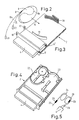
- Fig. 3 zeigt eine perspektivische Ansicht der Oberseite einer Endabschlußeinheit.
- Fig. 4 zeigt eine perspektivische Ansicht der Unterseite einer Endabschlußeinheit.
- Fig. 5 zeigt schematisch den Einlegeverlauf einer Gruppe von mit Steckanschlußelementen verbundenen LWL in Speicheraufnahmen nach Fig. 4.
- Fig. 1 shows a simplified perspective view of a switching distributor constructed according to the invention.
- Fig. 2 shows a memory element for a patch cord.
- Fig. 3 shows a perspective view of the top of an end termination unit.
- Fig. 4 shows a perspective view of the underside of an end termination unit.
- FIG. 5 schematically shows the course of insertion of a group of optical fibers connected to plug-in connection elements in memory receptacles according to FIG. 4.
Im Gehäuse 1 des Schaltverteilers nach Fig. 1 sind im unteren Bereich Endabschlußeinheiten 2 und 3 sowie weitere nicht dargestellte übereinander und schubladenartig ausziehbar angeordnet. Die Endabschlußeinheit 2 ist in ausgezogenem Zustand dargestellt. Diese unteren Endabschlußeinheiten sind jeweils mit einer Gruppe von zehn zu einem Flachband zusammengefaßten LWL eines ankommenden optischen Kabels verbunden. Jeder dieser zehn LWL ist optisch mit einem Steckanschlußelement der Steckerleiste 4 verbunden.In the
Im oberen Bereich des Gehäuses 1 sind Endabschlußeinheiten 5 ausziehbar übereinander angeordnet, an deren Steckanschlußelementen an der Steckerleiste 6 jeweils zehn LWL eines abgehenden optischen Kabels enden. Diese LWL können auch wieder zu einem Flachband zusammengefaßt sein oder sie können einzelne LWL einer Bündelader sein.In the upper area of the
Im allgemeinen ist die Anzahl der Endabschlußeinheiten 5 für abgehende Kabel größer als die entsprechende Anzahl für ankommende Kabel, da sehr viel mehr abgehende als ankommende optische Leitungen vorhanden sind. Von jedem Steckanschlußelement einer jeden unteren Endabschlußeinheit muß zu jedem beliebigen Steckanschlußelement einer jeden oberen Endabschlußeinheit eine optische Verbindung schaltbar sein. Dazu dienen einadrige Rangierleitungen 7 bzw. 8, welche beidseitig ein auf die Steckanschlußelemente der Steckerleisten 4 bzw. 6 passendes Gegensteckanschlußelement aufweisen. Die Länge der Rangierleitungen 7 und 8 entspricht dem längstmöglichen Schaltweg. Für kürzere Schaltwege nicht benötigte Längenabschnitte sind in flachen Speicherelementen 9 eingewickelt, von denen eine der Anzahl der Steckanschlußelemente einer Endabschlußeinheit 2 entsprechende Anzahl seitlich in Aufnahmehalterungen 10 einer Endabschlußeinheit 2 einschiebbar sind. Den oberen Endabschlußeinheiten 5 brauchen keine Speicherelemente zugeordnet zu werden, da nur maximal jeder der LWL der ankommenden Kabel mit je einem LWL der abgehenden Kabel zu verbinden ist.In general, the number of
Die Rangierleitung 7 stellt eine optische Verbindung zwischen den Steckanschlußelementen 11 und 12 her. Die Rangierleitung 8 verbindet die Steckanschlußelemente 13 und 14. In gleicher Weise können eine Vielzahl von Weiteren Schaltverbindungen auf beliebigem Wege hergestellt Werden. Auf ihrem Schaltweg sind die zu den oberen Endabschlußeinheiten 5 führenden Enden der Rangierleitungen 7 und 8, Welche von ihren Speicherelementen 9 ausgehend an Führungshalterungen 31 bzw. 15 festgelegt sind, außerhalb des Auszugsbereichs der Endabschlußeinheiten 2,3 und 5 am Rande des Gehäuses 1 in Führungshalterungen 16 eingelegt, welche als durch Einlegeschlitze geöffnete Ösen ausgebildet sind.The jumper 7 creates an optical connection between the
Im Bereich zwischen den Führungshalterungen 14 bzw. 15 einerseits und der die Rangierleitungen 7 bzw. 8 haltenden untersten Führungshalterung 16 ist eine geringe Freilänge vorzusehen, welche ein Ausziehen der Endabschlußeinheiten 2 bzw. 3 ohne unzulässige Krümmungen der Rangierleitungen erlaubt. Diese Freilänge kann dadurch kurz gehalten werden, daß die Aufnahmehalterungen 31 bzw. 15 von der Seite der Steckerleiste 4 zu den Speicherelementen 9 hin zurückversetzt angeordnet sind.In the area between the
Die anderen Enden der Rangierleitungen 7 und 8 sind auf sehr kurzem Wege zu den Steckanschlußelementen 11 bzw. 13 geführt und außer in den zurückversetzten Führungshalterungen 31 bzw. 15 in weiteren Halteschlitzen 17 bzw. 18 geführt. Auf diesem kurzen Wege entstehen nur sanfte Krümmungen der Rangierleitungen, wenn insbesondere von links kommende Rangierleitungen zu einem auf der rechten Hälfte der Steckerleiste 4 befindlichen Steckanschlußelementen bzw. umgekehrt geführt werden. Bei der erfindungsgemäßen Anordnung nach Fig. 1 sind die Rangierleitungen auf geordneten Bahnen geführt, so daß die Gefahr einer Beschädigung gering ist. Der Bereich vor den Endabschlußeinheiten und deren Steckanschlußelementen ist stets frei zugänglich. Auch eine Vielzahl von Schaltverbindungen bleibt stets überschaubar und verfolgbar.The other ends of the
Aufbau und Funktion der Endabschlußeinheiten 2 und der zugeordneten Speicherelemente 9 werden anhand der Figuren 2 bis 5 näher erläutert.The structure and function of the
In Fig. 3 ist eine Endabschlußeinheit 2 nach Fig. 1 in gleicher Lage vergrößert erkennbar. Dabei wurde zur besseren Verdeutlichung des erfindungsgemäßen Prinzips auf die Darstellung konstruktiver Einzelheiten verzichtet.3, an
In Fig. 4 ist die Endabschlußeinheit 2 in um 180o geschwenkter Lage dargestellt, so daß ihre in Fig. 1 nicht erkennbare Rückseite sichtbar wird.In FIG. 4, the
Die Ablagehalterungen 10 und 30 für eine Mehrzahl von einzulegenden Speicherelementen 9, von denen eines in Fig. 2 angedeutet ist, bestehen jeweils aus zwei Teilen, einem ebenflächigen Teil und einem der kreisrunden Außenkontur der Speicherelemente 9 angepaßten gekrümmten Teil, welche bei den Ablagehalterungen 10 und 30 in umgekehrter räumlicher Folge übereinander angeordnet sind. In die Führungen der unteren Abschnitte können von rechts her fünf Speicherelemente 9 übereinander eingelegt werden, in die Führungen der oberen Abschnitte von links her in Richtung des Pfeils 19 ebenfalls fünf weitere Speicherelemente 9.The
Im Speicherelement 9 (Fig. 2) ist die Rangierleitung 8 mit einem mittleren Bereich 8a durch einen S-förmigen Kanal des Speicherelements 9 geführt. Zur Erleichterung der Einlegbarkeit sind die Speicherelemente vorzugsweise zweiteilig ausgebildet. Durch das Zusammenfügen beider Teile wird der zunächst offen zugängliche Einlegekanal abgedeckt. ln eine radial nach außen offene Ringnut des Speicherelements 9 können danach beide Enden 8b und 8c gleichzeitig parallel eingewickelt werden. Dabei dient das kürzere Ende 8c mit dem Steckanschlußelement 20 zur Verbindung mit der Steckerleiste 4, während das längere Ende 8b mit dem Steckanschlußelement 21 zur Verbindung mit einer Steckerleiste 6 einer in Fig. 1 angedeuteten oberen Endabschlußeinheit 5 vorgesehen ist.In the storage element 9 (FIG. 2), the
Da die Rangierleitung 8 im S-förmigen Kanal des Speicherelements 9 locker geführt ist, kann das Speicherelement nach dem Herstellen der Steckverbindungen und dem Einlegen der Enden 8b in die Führungshalterung 15 und der Enden 8c in die Führungshalterungen 15 und 18 in eine solche mittlere Längenposition der Rangierleitung geschoben werden, daß nicht benötigte Längen der Enden 8b und 8c beim nachfolgenden Aufwickeln in dem Speicherelement verschwinden.Since the
In Fig. 4 sind auf der Rückseite der Endabschlußeinheit 2 Speicheraufnahmen 22 und 23 erkennbar. In die Speicheraufnahme 22 werden Windungen 24 (Fig. 5) eines ankommenden, zehn einzelne LWL enthaltenden LWL-Flachbandes 27, welches außer am Gehäuse 1 auch an einer Stelle 25 mit der Endabschlußeinheit 2 zugentlastet verbunden ist, spiralig hochkant eingelegt. Das Ende des LWL-Flachbandes 27 wird durch einen in der Zeichnung nicht erkennbaren Kanal in um 90o gedrehter Flachlage in die Speicheraufnahme 23 geführt (gestrichelter Bereich in Fig. 5). Wenn Spleißverbindungen 29 mit den Pigtails 26 der Steckanschlußelemente der Steckerleiste 4 hergestellt werden sollen, wird eine benötigte Verfügungslänge der Windung 24 aus der Speicheraufnahme 23 herausgezogen. Die nach der Spleißung nicht mehr benötigten Überlängen der pigtails 26 und des Anteils des LWL-Flachbandes 27 werden in die Speicheraufnahme 23 abgelegt (vgl. Windung 28 in Fig. 5).4
Claims (13)
dadurch gekennzeichnet, daß die Endabschlußeinheiten (2,5) als in den Schaltverteiler einschiebbare Einschübe ausgebildet sind, an welchen eine Gruppe (27) von LWL entweder eines ankommenden oder eines abgehenden Kabels zugentlastet gehalten ist und welche Speicheraufnahmen (22,23) zum Einlegen von zur Herstellung von Spleißverbindungen (29) benötigten Verfügungslängen der LWL aufweisen.2. Switch distributor according to claim 1,
characterized in that the end termination units (2,5) are designed as inserts which can be inserted into the switching distributor and on which a group (27) of fiber optic cables of either an incoming or an outgoing cable is kept strain-relieved and which memory receptacles (22, 23) for inserting have the required fiber lengths for making splice connections (29).
dadurch gekennzeichnet, daß zumindest einem Teil (2) der Endabschlußeinheiten Ablagehalterungen (10,30) für eine der Anzahl der Steckanschlußelementen (11,13) der Endabschlußeinheit (2) entsprechende Anzahl von Speicherelementen (9) räumlich zugeordnet sind.3. Switch distributor according to claim 1 or 2,
characterized in that at least a part (2) of the end termination units are spatially allocated to a number of storage elements (9) corresponding to the number of plug connection elements (11, 13) of the end termination unit (2).
dadurch gekennzeichnet, daß die Ablagehalterungen (10,30) Bestandteile von Endabschlußeinheiten (2) sind.4. Switch distributor according to claim 3,
characterized in that the storage brackets (10, 30) are components of end termination units (2).
dadurch gekennzeichnet, daß die Ablagehalterungen (10,30) den Endabschlußeinheiten (2) für die ankommenden Kabel zugeordnet sind.5. Switch distributor according to claim 3 or 4,
characterized in that the storage brackets (10, 30) are assigned to the end termination units (2) for the incoming cables.
dadurch gekennzeichnet, daß die Speicheraufnahmen (22,23) und die Ablagehalterungen (10,30) an gegenüberliegenden Seiten der Endabschlußeinheiten (2) angeordnet sind.6. Switch distributor according to one of claims 3 to 5,
characterized in that the storage receptacles (22, 23) and the storage brackets (10, 30) are arranged on opposite sides of the end termination units (2).
dadurch gekennzeichnet, daß die Speicherelemente (9) für die Rangierleitungen (7,8) im wesentlichen in senkrechter Richtung zur Einschubrichtung für die Endabschlußeinheiten (2) in deren Ablagehalterungen (10,30) einlegbar sind.7. Switch distributor according to one of claims 3 to 6,
characterized in that the storage elements (9) for the shunting lines (7, 8) can be inserted essentially in the direction perpendicular to the direction of insertion for the end termination units (2) in their storage holders (10, 30).
dadurch gekennzeichnet, daß den Ablagehalterungen (10,30) Führungshalterungen (14,15,17,18) für die von jedem Speicherelement (9) ausgehenden Enden (8b,8c) der Rangierleitungen (8) zugeordnet sind.8. Switch distributor according to one of claims 3 to 7,
characterized in that guide holders (14, 15, 17, 18) for the ends (8b, 8c) of the shunting lines (8) starting from each storage element (9) are associated with the storage holders (10, 30).
dadurch gekennzeichnet, daß die Führungshalterungen (14,15) derart an den Endabschlußeinheiten (2) angeordnet sind, daß die zu anderen Endabschlußeinheiten (5) zu führenden Enden (8b) der Rangierleitungen (8) im vorderen Bereich einer Endabschlußeinheit (2) frei und unbefestigt verlaufen.9. Switch distributor according to claim 8,
characterized in that the guide brackets (14, 15) are arranged on the end termination units (2) in such a way that the ends (8b) of the marshalling lines (8) to be led to other end termination units (5) in the front region of an end termination unit (2) are free and run unpaved.
dadurch gekennzeichnet, daß außerhalb des Ausziehbereiches der Endabschlußeinheiten (2,5) Führungshalterungen (16) zum Einlegen der Schaltlängen der Rangierleitungen (7,8) vorgesehen sind.10. Switch distributor according to one of claims 1 to 9,
characterized in that guide brackets (16) for inserting the switching lengths of the shunting lines (7, 8) are provided outside the extension area of the end termination units (2, 5).
dadurch gekennzeichnet, daß die Gruppen der Endabschlußeinheiten (2 bzw. 5) der ankommenden und der abgehenden Kabel in einer gemeinsamen Zeile angeordnet sind, und daß die Führungshalterungen (16) für die Schaltlängen der Rangierleitungen (7,8), vorzugsweise beidseitig, neben der Zeile von Endabschlußeinheiten (2,5) angeordnet sind.11. Switch distributor according to claim 10,
characterized in that the groups of end termination units (2 and 5) of the incoming and outgoing cables are arranged in a common line, and that the guide brackets (16) for the switching lengths of the shunting lines (7, 8), preferably on both sides, next to the Row of end units (2.5) are arranged.
dadurch gekennzeichnet, daß die Rangierleitungen (7,8) durch einen S-förmigen Kanal ihrer Speicherelemente (9) lose geführt sind und daß überschüssige Längen der Rangierleitungen (7,8) parallel und gemeinsam um einen Wickelkern der Speicherelemente (9) wickelbar sind.12. Switch distributor according to one of claims 1 to 11,
characterized in that the shunting lines (7, 8) are loosely guided through an S-shaped channel of their storage elements (9) and in that excess lengths of the shunting lines (7, 8) can be wound in parallel and together around a winding core of the storage elements (9).
dadurch gekennzeichnet, daß die Endabschlußeinheiten (2) zwei Speicheraufnahmen (22,23) aufweisen, von denen die erste (22) zum Einlegen einer Speicherlänge der Gesamtheit der in die Endabschlußeinheit (2) geführten LWL (27) dient, Während in der zweiten Speicheraufnahme (23) für die Herstellung der Spleißverbindungen (29) zwischen den einzelnen LWL und den pigtail-LWL (26) der Steckanschlußelemente benötigte Verfügungslängen der LWL und der pigtail-LWL (26) ablegbar sind.13. Switch distributor according to one of claims 1 to 12,
characterized in that the end termination units (2) have two memory receptacles (22, 23), the first (22) of which is used to insert a storage length of the entirety of the optical fibers (27) guided into the end termination unit (2), while in the second storage receptacle (23) for the production of the splice connections (29) between the individual fiber optic cables and the pigtail fiber optic cables (26) of the plug-in connection elements, the available lengths of the fiber optic cables and the pigtail fiber optic cables (26) can be stored.
Applications Claiming Priority (2)
| Application Number | Priority Date | Filing Date | Title |
|---|---|---|---|
| DE3838428A DE3838428A1 (en) | 1988-11-12 | 1988-11-12 | SWITCH DISTRIBUTOR FOR THE PRODUCTION OF FREELY SELECTABLE OPTICAL CONNECTORS |
| DE3838428 | 1988-11-12 |
Publications (3)
| Publication Number | Publication Date |
|---|---|
| EP0369524A2 true EP0369524A2 (en) | 1990-05-23 |
| EP0369524A3 EP0369524A3 (en) | 1991-03-06 |
| EP0369524B1 EP0369524B1 (en) | 1994-06-22 |
Family
ID=6367058
Family Applications (1)
| Application Number | Title | Priority Date | Filing Date |
|---|---|---|---|
| EP89202824A Expired - Lifetime EP0369524B1 (en) | 1988-11-12 | 1989-11-08 | Distribution rack for making freely selectable optical connections |
Country Status (5)
| Country | Link |
|---|---|
| US (1) | US5024498A (en) |
| EP (1) | EP0369524B1 (en) |
| JP (1) | JPH02211408A (en) |
| DE (2) | DE3838428A1 (en) |
| ES (1) | ES2058482T3 (en) |
Cited By (10)
| Publication number | Priority date | Publication date | Assignee | Title |
|---|---|---|---|---|
| DE4107228A1 (en) * | 1990-03-20 | 1991-09-26 | Loh Kg Rittal Werk | Optical cable splice-box - includes termination manifold chassis with telescopic and hinged system for optimum access |
| GB2242757A (en) * | 1990-03-20 | 1991-10-09 | Loh Kg Rittal Werk | Slidable light wave conductor splicing box |
| EP0474091A1 (en) * | 1990-09-03 | 1992-03-11 | Reichle + De-Massari AG Elektro-Ingenieure | Pothead device for signal transmission cables, particularly for glass fibres cables |
| DE4126125C1 (en) * | 1991-08-07 | 1992-10-22 | Rittal-Werk Rudolf Loh Gmbh & Co Kg, 6348 Herborn, De | Fibre=optic cable splice installation - has splice cassette arranged on rectangular board with fixing holes and cable clamps |
| EP0514638A1 (en) * | 1991-03-22 | 1992-11-25 | The Siemon Company | Fiber optic patch panel |
| EP0536496A2 (en) * | 1991-10-05 | 1993-04-14 | KRONE Aktiengesellschaft | Switching device for glass fibre cables of the telecommunication and data technology |
| FR2682488A1 (en) * | 1991-10-15 | 1993-04-16 | Capelle Bruno | OPTICAL FIBER MODULAR CABLES HEAD OF HIGH CAPACITY. |
| DE4308228C1 (en) * | 1993-03-16 | 1994-10-20 | Quante Ag | Main distributor for optical fibres in communications technology |
| EP0623832A1 (en) * | 1993-05-05 | 1994-11-09 | KRONE Aktiengesellschaft | Distribution mounting for cables |
| EP2749921A1 (en) * | 2012-12-31 | 2014-07-02 | illi-sys | Distributor device for fibre optic cables |
Families Citing this family (81)
| Publication number | Priority date | Publication date | Assignee | Title |
|---|---|---|---|---|
| US5071211A (en) * | 1988-12-20 | 1991-12-10 | Northern Telecom Limited | Connector holders and distribution frame and connector holder assemblies for optical cable |
| EP0479227B1 (en) * | 1990-10-04 | 1996-05-22 | Alcatel Cable Interface | Device for fixing and mounting unitary modules on a supporting frame |
| DE4034832A1 (en) * | 1990-11-02 | 1992-05-07 | Rheydt Kabelwerk Ag | Optical communications cable connection system - has stacked modules each receiving coupling field groups for different cable conductor groups |
| DE69208533T2 (en) * | 1991-06-10 | 1996-11-07 | Ibm | Retractable fiber optic connector for computers |
| ES1019586Y (en) * | 1991-12-12 | 1992-11-01 | Telefonica De Espana, S.A. | TERMINAL JOINT AND MODULAR OPTICAL DISTRIBUTION. |
| US5189723A (en) * | 1992-01-06 | 1993-02-23 | Adc Telecommunications, Inc. | Below ground cross-connect/splice sytem (BGX) |
| GB2265725B (en) * | 1992-04-02 | 1995-07-12 | Northern Telecom Ltd | Submarine repeaters |
| US5274731A (en) * | 1992-12-24 | 1993-12-28 | Adc Telecommunications, Inc. | Optical fiber cabinet |
| DE4334022C1 (en) * | 1993-10-06 | 1995-03-02 | Rose Walter Gmbh & Co Kg | Device for receiving splice cassettes for optical fibers, especially in cable sockets |
| US5640482A (en) * | 1995-08-31 | 1997-06-17 | The Whitaker Corporation | Fiber optic cable management rack |
| GB9603017D0 (en) * | 1996-02-14 | 1996-04-10 | Raychem Sa Nv | Optical fibre distribution system |
| US6353183B1 (en) | 1996-05-23 | 2002-03-05 | The Siemon Company | Adapter plate for use with cable adapters |
| US6504988B1 (en) * | 2000-01-24 | 2003-01-07 | Adc Telecommunications, Inc. | Cable management panel with sliding drawer |
| US6438310B1 (en) | 2000-01-24 | 2002-08-20 | Adc Telecommunications, Inc. | Cable management panel with sliding drawer |
| GB0013278D0 (en) * | 2000-06-01 | 2000-07-26 | Raychem Sa Nv | An optical fibre distribution rack |
| US6865331B2 (en) * | 2003-01-15 | 2005-03-08 | Adc Telecommunications, Inc. | Rotating radius limiter for cable management panel and methods |
| US7922269B2 (en) * | 2006-10-17 | 2011-04-12 | Adc Telecommunications, Inc. | Cabinet assembly including a scissors lift |
| US20090175588A1 (en) * | 2007-10-30 | 2009-07-09 | Adc Telecommunications, Inc. | Lifting a Terminal Enclosure in Below Ground Applications |
| US11294136B2 (en) | 2008-08-29 | 2022-04-05 | Corning Optical Communications LLC | High density and bandwidth fiber optic apparatuses and related equipment and methods |
| US8452148B2 (en) | 2008-08-29 | 2013-05-28 | Corning Cable Systems Llc | Independently translatable modules and fiber optic equipment trays in fiber optic equipment |
| US7856166B2 (en) | 2008-09-02 | 2010-12-21 | Corning Cable Systems Llc | High-density patch-panel assemblies for optical fiber telecommunications |
| ATE534049T1 (en) * | 2009-02-24 | 2011-12-15 | Ccs Technology Inc | CABLE HOLDING DEVICE OR ARRANGEMENT FOR USE WITH A CABLE |
| US8699838B2 (en) | 2009-05-14 | 2014-04-15 | Ccs Technology, Inc. | Fiber optic furcation module |
| US9075216B2 (en) | 2009-05-21 | 2015-07-07 | Corning Cable Systems Llc | Fiber optic housings configured to accommodate fiber optic modules/cassettes and fiber optic panels, and related components and methods |
| US8280216B2 (en) | 2009-05-21 | 2012-10-02 | Corning Cable Systems Llc | Fiber optic equipment supporting moveable fiber optic equipment tray(s) and module(s), and related equipment and methods |
| CN102460261B (en) * | 2009-06-19 | 2016-11-09 | 康宁光缆系统有限责任公司 | High capacity fiber optic connection infrastructure apparatus |
| US8712206B2 (en) | 2009-06-19 | 2014-04-29 | Corning Cable Systems Llc | High-density fiber optic modules and module housings and related equipment |
| EP3693778A1 (en) | 2009-06-19 | 2020-08-12 | Corning Optical Communications LLC | High density and bandwidth fiber optic apparatuses and related equipment and methods |
| WO2010148325A1 (en) * | 2009-06-19 | 2010-12-23 | Corning Cable Systems Llc | High fiber optic cable packing density apparatus |
| US20100322580A1 (en) * | 2009-06-22 | 2010-12-23 | Beamon Hubert B | Fiber Optic Cable Parking Device |
| US8625950B2 (en) * | 2009-12-18 | 2014-01-07 | Corning Cable Systems Llc | Rotary locking apparatus for fiber optic equipment trays and related methods |
| US8593828B2 (en) | 2010-02-04 | 2013-11-26 | Corning Cable Systems Llc | Communications equipment housings, assemblies, and related alignment features and methods |
| US8913866B2 (en) * | 2010-03-26 | 2014-12-16 | Corning Cable Systems Llc | Movable adapter panel |
| CA2796221C (en) | 2010-04-16 | 2018-02-13 | Ccs Technology, Inc. | Sealing and strain relief device for data cables |
| EP2381284B1 (en) | 2010-04-23 | 2014-12-31 | CCS Technology Inc. | Under floor fiber optic distribution device |
| US8660397B2 (en) | 2010-04-30 | 2014-02-25 | Corning Cable Systems Llc | Multi-layer module |
| US9632270B2 (en) | 2010-04-30 | 2017-04-25 | Corning Optical Communications LLC | Fiber optic housings configured for tool-less assembly, and related components and methods |
| US8879881B2 (en) | 2010-04-30 | 2014-11-04 | Corning Cable Systems Llc | Rotatable routing guide and assembly |
| US9075217B2 (en) | 2010-04-30 | 2015-07-07 | Corning Cable Systems Llc | Apparatuses and related components and methods for expanding capacity of fiber optic housings |
| US9519118B2 (en) | 2010-04-30 | 2016-12-13 | Corning Optical Communications LLC | Removable fiber management sections for fiber optic housings, and related components and methods |
| US8705926B2 (en) | 2010-04-30 | 2014-04-22 | Corning Optical Communications LLC | Fiber optic housings having a removable top, and related components and methods |
| US9720195B2 (en) | 2010-04-30 | 2017-08-01 | Corning Optical Communications LLC | Apparatuses and related components and methods for attachment and release of fiber optic housings to and from an equipment rack |
| US8718436B2 (en) | 2010-08-30 | 2014-05-06 | Corning Cable Systems Llc | Methods, apparatuses for providing secure fiber optic connections |
| US9279951B2 (en) | 2010-10-27 | 2016-03-08 | Corning Cable Systems Llc | Fiber optic module for limited space applications having a partially sealed module sub-assembly |
| US9116324B2 (en) | 2010-10-29 | 2015-08-25 | Corning Cable Systems Llc | Stacked fiber optic modules and fiber optic equipment configured to support stacked fiber optic modules |
| US8662760B2 (en) | 2010-10-29 | 2014-03-04 | Corning Cable Systems Llc | Fiber optic connector employing optical fiber guide member |
| CN203759315U (en) | 2010-11-30 | 2014-08-06 | 康宁光缆系统有限责任公司 | Optical fiber device |
| EP2671109A2 (en) | 2011-02-02 | 2013-12-11 | Corning Cable Systems LLC | Dense fiber optic connector assemblies and related connectors and cables suitable for establishing optical connections for optical backplanes in equipment racks |
| US9008485B2 (en) | 2011-05-09 | 2015-04-14 | Corning Cable Systems Llc | Attachment mechanisms employed to attach a rear housing section to a fiber optic housing, and related assemblies and methods |
| CN103649805B (en) | 2011-06-30 | 2017-03-15 | 康宁光电通信有限责任公司 | Fiber plant assembly of shell using non-U-width size and associated method |
| US8953924B2 (en) | 2011-09-02 | 2015-02-10 | Corning Cable Systems Llc | Removable strain relief brackets for securing fiber optic cables and/or optical fibers to fiber optic equipment, and related assemblies and methods |
| CN105068204B (en) | 2011-10-07 | 2018-08-10 | Adc电信公司 | Slidably optical link module with cable slack management |
| US9002166B2 (en) | 2011-10-07 | 2015-04-07 | Adc Telecommunications, Inc. | Slidable fiber optic connection module with cable slack management |
| US9170391B2 (en) | 2011-10-07 | 2015-10-27 | Adc Telecommunications, Inc. | Slidable fiber optic connection module with cable slack management |
| US9038832B2 (en) | 2011-11-30 | 2015-05-26 | Corning Cable Systems Llc | Adapter panel support assembly |
| US9075203B2 (en) | 2012-01-17 | 2015-07-07 | Adc Telecommunications, Inc. | Fiber optic adapter block |
| US9250409B2 (en) | 2012-07-02 | 2016-02-02 | Corning Cable Systems Llc | Fiber-optic-module trays and drawers for fiber-optic equipment |
| US9042702B2 (en) | 2012-09-18 | 2015-05-26 | Corning Cable Systems Llc | Platforms and systems for fiber optic cable attachment |
| US10082636B2 (en) | 2012-09-21 | 2018-09-25 | Commscope Technologies Llc | Slidable fiber optic connection module with cable slack management |
| US9195021B2 (en) | 2012-09-21 | 2015-11-24 | Adc Telecommunications, Inc. | Slidable fiber optic connection module with cable slack management |
| ES2551077T3 (en) | 2012-10-26 | 2015-11-16 | Ccs Technology, Inc. | Fiber optic management unit and fiber optic distribution device |
| EP2951633B1 (en) | 2013-01-29 | 2020-05-20 | CommScope Connectivity Belgium BVBA | Optical fiber distribution system |
| US9128262B2 (en) | 2013-02-05 | 2015-09-08 | Adc Telecommunications, Inc. | Slidable telecommunications tray with cable slack management |
| WO2014133943A1 (en) | 2013-02-27 | 2014-09-04 | Adc Telecommunications, Inc. | Slidable fiber optic connection module with cable slack management |
| US8985862B2 (en) | 2013-02-28 | 2015-03-24 | Corning Cable Systems Llc | High-density multi-fiber adapter housings |
| AP2015008820A0 (en) | 2013-04-24 | 2015-10-31 | Adc Czech Republic Sro | Optical fiber distribution system |
| AU2014257660B2 (en) | 2013-04-24 | 2018-03-22 | CommScope Connectivity Belgium BVBA | Universal mounting mechanism for mounting a telecommunications chassis to a telecommunications fixture |
| EP3230780B1 (en) | 2014-12-10 | 2023-10-25 | CommScope Technologies LLC | Fiber optic cable slack management module |
| WO2016156611A1 (en) | 2015-04-03 | 2016-10-06 | CommScope Connectivity Belgium BVBA | Telecommunications distribution elements |
| WO2017184501A1 (en) | 2016-04-19 | 2017-10-26 | Commscope, Inc. Of North Carolina | Door assembly for a telecommunications chassis with a combination hinge structure |
| EP3446554B1 (en) | 2016-04-19 | 2020-12-02 | CommScope, Inc. of North Carolina | Telecommunications chassis with slidable trays |
| WO2018226959A1 (en) | 2017-06-07 | 2018-12-13 | Commscope Technologies Llc | Fiber optic adapter and cassette |
| US11385429B2 (en) | 2017-10-18 | 2022-07-12 | Commscope Technologies Llc | Fiber optic connection cassette |
| US11852882B2 (en) | 2018-02-28 | 2023-12-26 | Commscope Technologies Llc | Packaging assembly for telecommunications equipment |
| WO2019204317A1 (en) | 2018-04-16 | 2019-10-24 | Commscope Technologies Llc | Adapter structure |
| EP3781973A1 (en) | 2018-04-17 | 2021-02-24 | CommScope Connectivity Belgium BVBA | Telecommunications distribution elements |
| EP3845044B1 (en) | 2018-08-31 | 2023-02-15 | CommScope Connectivity Belgium BVBA | Frame assemblies for optical fiber distribution elements |
| EP3844973A1 (en) | 2018-08-31 | 2021-07-07 | CommScope Connectivity Belgium BVBA | Frame assemblies for optical fiber distribution elements |
| EP3844972B1 (en) | 2018-08-31 | 2022-08-03 | CommScope Connectivity Belgium BVBA | Frame assemblies for optical fiber distribution elements |
| WO2020043909A1 (en) | 2018-08-31 | 2020-03-05 | CommScope Connectivity Belgium BVBA | Frame assemblies for optical fiber distribution elements |
| US11947177B2 (en) | 2019-01-25 | 2024-04-02 | CommScope Connectivity Belgium BVBA | Frame assemblies for optical fiber distribution elements |
Citations (9)
| Publication number | Priority date | Publication date | Assignee | Title |
|---|---|---|---|---|
| EP0116480A1 (en) * | 1983-01-05 | 1984-08-22 | SAT (Société Anonyme de Télécommunications),Société Anonyme | Connecting and mixing box for optical fibres |
| WO1985004960A1 (en) * | 1984-04-16 | 1985-11-07 | American Telephone & Telegraph Company | Lightguide distributing unit |
| EP0215520A2 (en) * | 1985-09-11 | 1987-03-25 | Philips Patentverwaltung GmbH | Process for establishing a connection between two optical fibres, and arrangement to perform this process |
| EP0215668A2 (en) * | 1985-09-17 | 1987-03-25 | Adc Telecommunications, Inc. | Optical fiber distribution apparatus |
| EP0220969A1 (en) * | 1985-09-06 | 1987-05-06 | Paul Valleix | Arrangement for optical connexions |
| EP0226805A1 (en) * | 1985-11-18 | 1987-07-01 | Alcatel Cit | Distributor arrangement for fibre-optic cable ends |
| DE8809714U1 (en) * | 1988-07-29 | 1988-09-22 | Siemens Ag, 1000 Berlin Und 8000 Muenchen, De | |
| EP0288808A2 (en) * | 1987-04-28 | 1988-11-02 | Reichle + De-Massari AG Elektro-Ingenieure | Terminating box for signal transmission cables, in particular optical cables |
| EP0341027A2 (en) * | 1988-05-02 | 1989-11-08 | Gte Control Devices Of Puerto Rico Incorporated | Fiber distribution panel |
Family Cites Families (8)
| Publication number | Priority date | Publication date | Assignee | Title |
|---|---|---|---|---|
| US4792203A (en) * | 1985-09-17 | 1988-12-20 | Adc Telecommunications, Inc. | Optical fiber distribution apparatus |
| GB2198549A (en) * | 1986-12-12 | 1988-06-15 | Telephone Cables Ltd | Optical fibre distribution frame |
| US4824196A (en) * | 1987-05-26 | 1989-04-25 | Minnesota Mining And Manufacturing Company | Optical fiber distribution panel |
| US4805979A (en) * | 1987-09-04 | 1989-02-21 | Minnesota Mining And Manufacturing Company | Fiber optic cable splice closure |
| US4895425A (en) * | 1988-02-26 | 1990-01-23 | Nippon Telegraph And Telephone Corporation | Plug-in optical fiber connector |
| US4884863A (en) * | 1989-03-06 | 1989-12-05 | Siecor Corporation | Optical fiber splicing enclosure for installation in pedestals |
| US4971421A (en) * | 1989-09-29 | 1990-11-20 | Reliance Comm/Tec Corporation | Fiber optic splice and patch enclosure |
| US4976510B2 (en) * | 1989-11-20 | 1995-05-09 | Siecor Corp | Communication outlet |
-
1988
- 1988-11-12 DE DE3838428A patent/DE3838428A1/en not_active Withdrawn
-
1989
- 1989-11-08 ES ES89202824T patent/ES2058482T3/en not_active Expired - Lifetime
- 1989-11-08 EP EP89202824A patent/EP0369524B1/en not_active Expired - Lifetime
- 1989-11-08 DE DE58907946T patent/DE58907946D1/en not_active Expired - Fee Related
- 1989-11-09 US US07/434,644 patent/US5024498A/en not_active Expired - Fee Related
- 1989-11-13 JP JP1292533A patent/JPH02211408A/en active Pending
Patent Citations (9)
| Publication number | Priority date | Publication date | Assignee | Title |
|---|---|---|---|---|
| EP0116480A1 (en) * | 1983-01-05 | 1984-08-22 | SAT (Société Anonyme de Télécommunications),Société Anonyme | Connecting and mixing box for optical fibres |
| WO1985004960A1 (en) * | 1984-04-16 | 1985-11-07 | American Telephone & Telegraph Company | Lightguide distributing unit |
| EP0220969A1 (en) * | 1985-09-06 | 1987-05-06 | Paul Valleix | Arrangement for optical connexions |
| EP0215520A2 (en) * | 1985-09-11 | 1987-03-25 | Philips Patentverwaltung GmbH | Process for establishing a connection between two optical fibres, and arrangement to perform this process |
| EP0215668A2 (en) * | 1985-09-17 | 1987-03-25 | Adc Telecommunications, Inc. | Optical fiber distribution apparatus |
| EP0226805A1 (en) * | 1985-11-18 | 1987-07-01 | Alcatel Cit | Distributor arrangement for fibre-optic cable ends |
| EP0288808A2 (en) * | 1987-04-28 | 1988-11-02 | Reichle + De-Massari AG Elektro-Ingenieure | Terminating box for signal transmission cables, in particular optical cables |
| EP0341027A2 (en) * | 1988-05-02 | 1989-11-08 | Gte Control Devices Of Puerto Rico Incorporated | Fiber distribution panel |
| DE8809714U1 (en) * | 1988-07-29 | 1988-09-22 | Siemens Ag, 1000 Berlin Und 8000 Muenchen, De |
Cited By (14)
| Publication number | Priority date | Publication date | Assignee | Title |
|---|---|---|---|---|
| GB2242757B (en) * | 1990-03-20 | 1994-07-06 | Loh Kg Rittal Werk | Slidable light-wave conductor splicing box |
| GB2242757A (en) * | 1990-03-20 | 1991-10-09 | Loh Kg Rittal Werk | Slidable light wave conductor splicing box |
| US5142607A (en) * | 1990-03-20 | 1992-08-25 | Rittal-Werk Rudolf Loh Gmbh & Co. Kg | Splice box for optical wave guide |
| DE4107228A1 (en) * | 1990-03-20 | 1991-09-26 | Loh Kg Rittal Werk | Optical cable splice-box - includes termination manifold chassis with telescopic and hinged system for optimum access |
| EP0474091A1 (en) * | 1990-09-03 | 1992-03-11 | Reichle + De-Massari AG Elektro-Ingenieure | Pothead device for signal transmission cables, particularly for glass fibres cables |
| EP0514638A1 (en) * | 1991-03-22 | 1992-11-25 | The Siemon Company | Fiber optic patch panel |
| DE4126125C1 (en) * | 1991-08-07 | 1992-10-22 | Rittal-Werk Rudolf Loh Gmbh & Co Kg, 6348 Herborn, De | Fibre=optic cable splice installation - has splice cassette arranged on rectangular board with fixing holes and cable clamps |
| EP0536496A2 (en) * | 1991-10-05 | 1993-04-14 | KRONE Aktiengesellschaft | Switching device for glass fibre cables of the telecommunication and data technology |
| EP0536496A3 (en) * | 1991-10-05 | 1994-03-23 | Krone Ag | |
| EP0538164A1 (en) * | 1991-10-15 | 1993-04-21 | France Telecom | Distribution head for high capacity optical cables |
| FR2682488A1 (en) * | 1991-10-15 | 1993-04-16 | Capelle Bruno | OPTICAL FIBER MODULAR CABLES HEAD OF HIGH CAPACITY. |
| DE4308228C1 (en) * | 1993-03-16 | 1994-10-20 | Quante Ag | Main distributor for optical fibres in communications technology |
| EP0623832A1 (en) * | 1993-05-05 | 1994-11-09 | KRONE Aktiengesellschaft | Distribution mounting for cables |
| EP2749921A1 (en) * | 2012-12-31 | 2014-07-02 | illi-sys | Distributor device for fibre optic cables |
Also Published As
| Publication number | Publication date |
|---|---|
| US5024498A (en) | 1991-06-18 |
| DE3838428A1 (en) | 1990-05-31 |
| EP0369524B1 (en) | 1994-06-22 |
| JPH02211408A (en) | 1990-08-22 |
| EP0369524A3 (en) | 1991-03-06 |
| DE58907946D1 (en) | 1994-07-28 |
| ES2058482T3 (en) | 1994-11-01 |
Similar Documents
| Publication | Publication Date | Title |
|---|---|---|
| EP0369524B1 (en) | Distribution rack for making freely selectable optical connections | |
| DE3025700C2 (en) | Sleeve for multi-pair fiber optic cables | |
| EP1891474B1 (en) | Optical waveguide distribution device | |
| EP0149250B1 (en) | Distribution mounting for the end parts of glassfibre cables | |
| DE19611770C2 (en) | Manageable splice cassette | |
| DE4229884C2 (en) | Device for storing the single and loose tubes of fiber optic cables in distribution facilities for telecommunications and data technology | |
| DE10317620B4 (en) | Fiber Coupler | |
| DE3133586C2 (en) | Splice carrier for fiber optic cables | |
| DE69728967T2 (en) | DISTRIBUTION SYSTEM FOR OPTICAL FIBERS | |
| DE2735106C2 (en) | Cable set for a telecommunication cable | |
| EP0216073B1 (en) | Storing device for optical-fibre connectors | |
| EP0872750B1 (en) | Junction box with a holding device for cassettes for storing optical fibres and their splices | |
| DE69930212T2 (en) | Fiber optic interconnect termination with a fiber management frame | |
| DE102010006611A1 (en) | Holder for at least one cassette | |
| EP0579019B1 (en) | Optical fibre splice cassette lay device for cable coupling box | |
| DE2914217C2 (en) | Cassette for holding the supply lengths of optical fibers | |
| DE60123059T2 (en) | BUILDINGS TO BE USED IN BUILDINGS TO CONNECT BETWEEN OPTICAL FIBERS AND WORKPLACES | |
| DE3706518A1 (en) | Method and arrangement for winding by means of a winding cassette the excess lengths of optical waveguides which are connected to one another | |
| DE4438668A1 (en) | Cassette for storage of excess lengths and splices of optical cable | |
| DE4405666A1 (en) | Universal connection unit for optical fibers | |
| DE4308228C1 (en) | Main distributor for optical fibres in communications technology | |
| AT397331B (en) | FRAME FOR TELECOMMUNICATION DEVICES | |
| EP0373735A2 (en) | Arrangement with several splicing modules | |
| DE3540472A1 (en) | Device for storing fibres of optical fibre cables in distribution devices in the telecommunication network | |
| DE4439853A1 (en) | Junction unit for optic fibres |
Legal Events
| Date | Code | Title | Description |
|---|---|---|---|
| PUAI | Public reference made under article 153(3) epc to a published international application that has entered the european phase |
Free format text: ORIGINAL CODE: 0009012 |
|
| AK | Designated contracting states |
Kind code of ref document: A2 Designated state(s): DE ES FR GB IT |
|
| PUAL | Search report despatched |
Free format text: ORIGINAL CODE: 0009013 |
|
| AK | Designated contracting states |
Kind code of ref document: A3 Designated state(s): DE ES FR GB IT |
|
| 17P | Request for examination filed |
Effective date: 19910808 |
|
| 17Q | First examination report despatched |
Effective date: 19930324 |
|
| GRAA | (expected) grant |
Free format text: ORIGINAL CODE: 0009210 |
|
| AK | Designated contracting states |
Kind code of ref document: B1 Designated state(s): DE ES FR GB IT |
|
| REF | Corresponds to: |
Ref document number: 58907946 Country of ref document: DE Date of ref document: 19940728 |
|
| ITF | It: translation for a ep patent filed |
Owner name: ING. C. GREGORJ S.P.A. |
|
| GBT | Gb: translation of ep patent filed (gb section 77(6)(a)/1977) |
Effective date: 19940913 |
|
| ET | Fr: translation filed | ||
| ITPR | It: changes in ownership of a european patent |
Owner name: CAMBIO RAGIONE SOCIALE;PHILIPS ELECTRONICS N.V. |
|
| PLBE | No opposition filed within time limit |
Free format text: ORIGINAL CODE: 0009261 |
|
| STAA | Information on the status of an ep patent application or granted ep patent |
Free format text: STATUS: NO OPPOSITION FILED WITHIN TIME LIMIT |
|
| REG | Reference to a national code |
Ref country code: FR Ref legal event code: CD |
|
| 26N | No opposition filed | ||
| REG | Reference to a national code |
Ref country code: FR Ref legal event code: TP |
|
| REG | Reference to a national code |
Ref country code: GB Ref legal event code: 732E |
|
| REG | Reference to a national code |
Ref country code: ES Ref legal event code: PC2A Owner name: ALCATEL KABEL AG & CO. |
|
| PGFP | Annual fee paid to national office [announced via postgrant information from national office to epo] |
Ref country code: GB Payment date: 19961021 Year of fee payment: 8 |
|
| PGFP | Annual fee paid to national office [announced via postgrant information from national office to epo] |
Ref country code: ES Payment date: 19961107 Year of fee payment: 8 |
|
| PGFP | Annual fee paid to national office [announced via postgrant information from national office to epo] |
Ref country code: FR Payment date: 19961114 Year of fee payment: 8 Ref country code: DE Payment date: 19961114 Year of fee payment: 8 |
|
| PG25 | Lapsed in a contracting state [announced via postgrant information from national office to epo] |
Ref country code: GB Free format text: LAPSE BECAUSE OF NON-PAYMENT OF DUE FEES Effective date: 19971108 |
|
| PG25 | Lapsed in a contracting state [announced via postgrant information from national office to epo] |
Ref country code: ES Free format text: LAPSE BECAUSE OF NON-PAYMENT OF DUE FEES Effective date: 19971109 |
|
| PG25 | Lapsed in a contracting state [announced via postgrant information from national office to epo] |
Ref country code: FR Free format text: THE PATENT HAS BEEN ANNULLED BY A DECISION OF A NATIONAL AUTHORITY Effective date: 19971130 |
|
| GBPC | Gb: european patent ceased through non-payment of renewal fee |
Effective date: 19971108 |
|
| PG25 | Lapsed in a contracting state [announced via postgrant information from national office to epo] |
Ref country code: DE Free format text: LAPSE BECAUSE OF NON-PAYMENT OF DUE FEES Effective date: 19980801 |
|
| REG | Reference to a national code |
Ref country code: FR Ref legal event code: ST |
|
| REG | Reference to a national code |
Ref country code: ES Ref legal event code: FD2A Effective date: 19981212 |
|
| PG25 | Lapsed in a contracting state [announced via postgrant information from national office to epo] |
Ref country code: IT Free format text: LAPSE BECAUSE OF NON-PAYMENT OF DUE FEES;WARNING: LAPSES OF ITALIAN PATENTS WITH EFFECTIVE DATE BEFORE 2007 MAY HAVE OCCURRED AT ANY TIME BEFORE 2007. THE CORRECT EFFECTIVE DATE MAY BE DIFFERENT FROM THE ONE RECORDED. Effective date: 20051108 |