EP3230780B1 - Fiber optic cable slack management module - Google Patents
Fiber optic cable slack management module Download PDFInfo
- Publication number
- EP3230780B1 EP3230780B1 EP15867719.5A EP15867719A EP3230780B1 EP 3230780 B1 EP3230780 B1 EP 3230780B1 EP 15867719 A EP15867719 A EP 15867719A EP 3230780 B1 EP3230780 B1 EP 3230780B1
- Authority
- EP
- European Patent Office
- Prior art keywords
- cable
- fiber optic
- cables
- management module
- cable slack
- Prior art date
- Legal status (The legal status is an assumption and is not a legal conclusion. Google has not performed a legal analysis and makes no representation as to the accuracy of the status listed.)
- Active
Links
- 239000000835 fiber Substances 0.000 title claims description 56
- 230000002093 peripheral effect Effects 0.000 claims description 12
- 230000014759 maintenance of location Effects 0.000 claims description 5
- 230000007704 transition Effects 0.000 claims description 2
- 239000013307 optical fiber Substances 0.000 description 6
- 238000005452 bending Methods 0.000 description 2
- 238000004140 cleaning Methods 0.000 description 2
- 238000004891 communication Methods 0.000 description 2
- 238000009434 installation Methods 0.000 description 2
- 238000002955 isolation Methods 0.000 description 2
- 230000004048 modification Effects 0.000 description 2
- 238000012986 modification Methods 0.000 description 2
- 230000001419 dependent effect Effects 0.000 description 1
- 238000000034 method Methods 0.000 description 1
- 230000003287 optical effect Effects 0.000 description 1
- 238000004804 winding Methods 0.000 description 1
Images


Classifications
-
- G—PHYSICS
- G02—OPTICS
- G02B—OPTICAL ELEMENTS, SYSTEMS OR APPARATUS
- G02B6/00—Light guides; Structural details of arrangements comprising light guides and other optical elements, e.g. couplings
- G02B6/24—Coupling light guides
- G02B6/36—Mechanical coupling means
- G02B6/38—Mechanical coupling means having fibre to fibre mating means
- G02B6/3807—Dismountable connectors, i.e. comprising plugs
- G02B6/381—Dismountable connectors, i.e. comprising plugs of the ferrule type, e.g. fibre ends embedded in ferrules, connecting a pair of fibres
- G02B6/3825—Dismountable connectors, i.e. comprising plugs of the ferrule type, e.g. fibre ends embedded in ferrules, connecting a pair of fibres with an intermediate part, e.g. adapter, receptacle, linking two plugs
-
- G—PHYSICS
- G02—OPTICS
- G02B—OPTICAL ELEMENTS, SYSTEMS OR APPARATUS
- G02B6/00—Light guides; Structural details of arrangements comprising light guides and other optical elements, e.g. couplings
- G02B6/44—Mechanical structures for providing tensile strength and external protection for fibres, e.g. optical transmission cables
- G02B6/4439—Auxiliary devices
- G02B6/4457—Bobbins; Reels
-
- G—PHYSICS
- G02—OPTICS
- G02B—OPTICAL ELEMENTS, SYSTEMS OR APPARATUS
- G02B6/00—Light guides; Structural details of arrangements comprising light guides and other optical elements, e.g. couplings
- G02B6/24—Coupling light guides
- G02B6/36—Mechanical coupling means
- G02B6/38—Mechanical coupling means having fibre to fibre mating means
- G02B6/3807—Dismountable connectors, i.e. comprising plugs
- G02B6/3873—Connectors using guide surfaces for aligning ferrule ends, e.g. tubes, sleeves, V-grooves, rods, pins, balls
- G02B6/3874—Connectors using guide surfaces for aligning ferrule ends, e.g. tubes, sleeves, V-grooves, rods, pins, balls using tubes, sleeves to align ferrules
-
- G—PHYSICS
- G02—OPTICS
- G02B—OPTICAL ELEMENTS, SYSTEMS OR APPARATUS
- G02B6/00—Light guides; Structural details of arrangements comprising light guides and other optical elements, e.g. couplings
- G02B6/24—Coupling light guides
- G02B6/36—Mechanical coupling means
- G02B6/38—Mechanical coupling means having fibre to fibre mating means
- G02B6/3807—Dismountable connectors, i.e. comprising plugs
- G02B6/389—Dismountable connectors, i.e. comprising plugs characterised by the method of fastening connecting plugs and sockets, e.g. screw- or nut-lock, snap-in, bayonet type
- G02B6/3893—Push-pull type, e.g. snap-in, push-on
-
- G—PHYSICS
- G02—OPTICS
- G02B—OPTICAL ELEMENTS, SYSTEMS OR APPARATUS
- G02B6/00—Light guides; Structural details of arrangements comprising light guides and other optical elements, e.g. couplings
- G02B6/44—Mechanical structures for providing tensile strength and external protection for fibres, e.g. optical transmission cables
- G02B6/4439—Auxiliary devices
- G02B6/444—Systems or boxes with surplus lengths
- G02B6/4452—Distribution frames
-
- H—ELECTRICITY
- H01—ELECTRIC ELEMENTS
- H01R—ELECTRICALLY-CONDUCTIVE CONNECTIONS; STRUCTURAL ASSOCIATIONS OF A PLURALITY OF MUTUALLY-INSULATED ELECTRICAL CONNECTING ELEMENTS; COUPLING DEVICES; CURRENT COLLECTORS
- H01R13/00—Details of coupling devices of the kinds covered by groups H01R12/70 or H01R24/00 - H01R33/00
- H01R13/72—Means for accommodating flexible lead within the holder
-
- G—PHYSICS
- G02—OPTICS
- G02B—OPTICAL ELEMENTS, SYSTEMS OR APPARATUS
- G02B6/00—Light guides; Structural details of arrangements comprising light guides and other optical elements, e.g. couplings
- G02B6/24—Coupling light guides
- G02B6/36—Mechanical coupling means
- G02B6/38—Mechanical coupling means having fibre to fibre mating means
- G02B6/3807—Dismountable connectors, i.e. comprising plugs
- G02B6/3897—Connectors fixed to housings, casing, frames or circuit boards
-
- G—PHYSICS
- G02—OPTICS
- G02B—OPTICAL ELEMENTS, SYSTEMS OR APPARATUS
- G02B6/00—Light guides; Structural details of arrangements comprising light guides and other optical elements, e.g. couplings
- G02B6/44—Mechanical structures for providing tensile strength and external protection for fibres, e.g. optical transmission cables
- G02B6/4439—Auxiliary devices
- G02B6/444—Systems or boxes with surplus lengths
- G02B6/4453—Cassettes
Definitions
- the present invention relates to apparatus and methods for termination and storage of optical fiber cables, such as distribution cables.
- a further concern related to termination and storage of optical fiber cables is the ease of access to the cables and the terminations. Such ease of use is desired during assembly, during installation in the field, and later when changes or modifications to the system are desired requiring adding or removing terminations, or when cleaning and checking the terminations.
- a further concern in the area of termination and storage of optical fiber cables includes protecting the optical fiber from damage from excess bending below the minimum bend radius of the cable. Such protection of the fibers is desired during assembly and installation, and later when individual terminations and cables are accessed for cleaning or modification.
- Prior art document US 2014/259602 A1 discloses a telecommunications assembly including a tray assembly including a tray and a cable spool assembly rotatably mounted to the tray.
- the cable spool assembly includes a hub, a first flange engaged to the hub, and a second flange engaged to the hub opposite the first flange.
- a cable can be wound around the hub between the flanges for storage on the cable spool assembly.
- the second flange includes an outer surface.
- the outer surface includes a cable management area and a termination area disposed adjacent to the cable management area.
- One or more cassettes can be mounted to the termination region of the cable spool assembly for paying-out a cable patch cord.
- US 2011/268414 A1 discloses a multi-layer module that includes a multi-fiber cable storage layer having a cable entry opening and a cable winding structure. It further has a splice storage layer that is discrete from the multi-fiber cable storage layer and has a splice layer receiving opening in communication with the multi-fiber cable storage layer and a slack storage area.
- the multi-layer module may also include a pigtail storage layer that is discrete from both the multi-fiber cable storage layer and the splice storage layer, the pigtail storage layer having a pigtail connector area and a pigtail storage area, the pigtail storage area comprising a pigtail storage layer receiving opening in communication with the splice storage layer.
- US 2007/047894 A1 discloses telecommunications management devices having a plurality of cable management trays.
- the trays are selectively moveable out of an aligned arrangement in order to access the cables and terminations on each tray.
- Each tray includes a first cable access location for cables entering the tray, and a second cable access location for cables exiting the tray.
- a pivoting cover including mounting locations for cable terminations is provided on each tray.
- US 2013/287359 A1 discloses a payout cassette for a telecommunications cable.
- the telecommunications cable extends between a first end and a second end.
- the payout cassette pays-out the telecommunications cable when the first end of the telecommunications cable is pulled away from the payout cassette.
- the cassette also stores the telecommunications cable.
- the cassette includes a storage area and a transitioning area.
- the storage area is adapted to store a stored portion of the telecommunications cable.
- the transitioning area is adapted to transition the telecommunications cable from the stored portion within the storage area to a paid-out portion of the telecommunications cable that is external to the storage area.
- the transitioning area is at least partially positioned within an interior of the storage area.
- the invention provides a fiber optic telecommunications system according to independent claim 1. Further embodiments are provided by the dependent claims.
- inventive aspects can relate to individual features and combinations of features. It is to be understood that both the foregoing general description and the following detailed description are exemplary and explanatory only and are not restrictive of the broad inventive concepts upon which the embodiments disclosed herein are based.
- FIGS. 1-17 a fiber optic cable slack management/storage module 10 is illustrated.
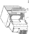
- a plurality of the cable slack management modules 10 is illustrated as mounted on a telecommunications fixture 12 (i.e., frame, chassis) in a stacked arrangement.
- the cable slack management modules 10 are mounted adjacent sliding adapter modules 14.
- the cable slack management modules 10 are configured to manage the cabling 16 (or cable slack) extending from connectors 18 coupled to the adapter modules 14.
- the cabled fibers 16 terminated by the connectors 18 coupled to the sliding adapter modules 14 are input into the cable slack management module 10 via an optical device 20 (e.g., a fan-out in the depicted embodiment).
- the configuration of the cable slack management module 10 allows extra cable slack 16 to be stored therewithin such that the extra cable slack 16 can be used when the sliding adapter modules 14 are moved outwardly from the telecommunications fixture 12, without violating minimum bending requirements.
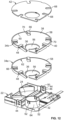
- each cable slack management module 10 includes a base 22 with a bottom wall 24 and vertically extending peripheral walls 26.
- the base 22 defines a fan-out pocket 25 for receiving the fan-out 20 with a snap-fit interlock.
- the fan-out pocket 25 is defined partially by the bottom wall 24.
- the fan-out pocket 25 and the fan-out 20 define the fiber input portion 28 of the cable slack management module 10.
- portions of the front and rear peripheral walls 26 of the base 22 define flexible cantilever arms 30 for providing a snap-fit interlock with the telecommunications fixture 12.
- the base 22 defines a first spool 32 extending upwardly from the bottom wall 24 of the base 22.
- the first spool 32 is one of the structures that provide the minimum bend radius protection for the cables 16 within the cable slack management module 10.
- each cable slack management module 10 also defines a pair of cable storage trays 34.
- the trays 34 are mounted in a stacked arrangement onto the base 22 and define a lower tray 34a and an upper tray 34b. Cables 16 enter the individual trays 34 via a ramp 36 defined by each tray 34. After the fibers 16 are input into the cable slack management module 10 via the fan-out 20, half of the separated and cabled fibers 16 enter the lower tray 34a via the ramp 36 of the lower tray 34a and half of the separated and cabled fibers 16 enter the upper tray 34b via the ramp 36 of the upper tray 34b.
- the upper tray 34b (the floor 38 thereof) forms the cover 40 of the lower tray 34a.
- the upper tray 34b defines a separate removable cover 42.
- the trays 34 are mounted via a snap-fit interlock to the base 22.
- a flexible portion 44 of both the front peripheral wall 26 and the rear peripheral wall 26 of the base 22 defines notches 46 for receiving tabs 48 extending outwardly from the trays 34 for keeping the trays 34 mounted within the base 22.
- the removable cover 42 of the upper tray 34b is also held in place by an inwardly extending tab 50 of the flexible portion 44 of the rear peripheral wall 26 and flexible cantilever arms 52 defined by the first spool 32.
- the cover 42 used with the upper tray 34b may be provided with a handle 54 to facilitate mounting and removal (see FIGS. 5-7 ).
- Each of the upper and lower trays 34 defines an opening 56 through which the first spool 32 extends.
- the first spool 32 extends all the way from the bottom wall 24 to the cover 42 of the upper tray 34b.
- Each tray 34 also includes a curved peripheral wall 58, the inner face 60 of which defines a second spool 62.
- the second spool 62 defined by each tray 34 cooperates with the first spool 32 in keeping the cable slack 16 stored and managed without violating minimum bend radius requirements.
- the second spool 62 (i.e., the inner face 60 of the curved peripheral wall 58 of each tray 34) is configured to contact the cables 16 within the tray 34 when the cables 16 are in a relaxed state (when the sliding adapter modules 14 are in a non-extended position).
- An outer face 64 of the first spool 32 is configured to contact the cables 16 within the tray 34 when the cables 16 are pulled (when the sliding adapter modules 14 are moved to an extended position).
- the combination of the first spool 32 and the second spool 62 provides the cables 16 with bend radius protection both in a relaxed state and in a pulled, tensioned state.
- Each tray 34 also defines a plurality of cable retention fingers 66 extending inwardly from the peripheral wall 58.
- the cable retention fingers 66 facilitate initial assembly of the cable slack management module 10 as the cables 16 are being lead from the fan-out 20, up the ramps 36 and into the trays 34.
- the cable retention fingers 66 fit within notches 68 defined by the cover 42 for the upper tray 34b and notches 70 defined by the floor 38 of the upper tray 34b for the lower tray 34a. In this manner, a smooth, flush ceiling is created for each of the trays 34 and the cables 16 can move without any obstruction.
- the cable exit portion 72 of the cable slack management module 10 is defined adjacent the first spool 32 and at least partially by the inner face 60 of the peripheral wall 58 of each tray 34 (i.e., the second spool 62), where the cable exit 72 is generally defined by a channel 74 positioned between the first and second spools 32, 62 as can be seen in FIGS. 10 , 11 , and 14-16 .
- the cable exit portion 72 is generally aligned with the fiber input portion 28 of the cable slack management module 10 when viewing the module 10 in a front to back direction.
- the optical fibers 16 enter the cable slack management module 10 via the fan-out 20 at a first common plane 76.
- the separated and cabled fibers 16 are then directed to multiple levels defined by the trays 34 via the ramps 36.
- the cables 16 are looped once around the trays 34 and exit the cable slack management module 10 via the cable exit channel 74. It should be noted that in the depicted embodiment, half of the cabled fibers 16 coming from the fan-out 20 are directed into the lower tray 34a and half are directed into the upper tray 34b.
- the cables 16 exiting the cable slack management module 10 are terminated with fiber optic connectors 18 that are coupled to the adapters 17 of the sliding adapter modules 14.
- the cables 16 output from the cable slack management module 10 may be terminated with other types or footprints of connectors 18 such as SC or LX.5, such connectors 18 leading to adapter modules 14 having adapters 17 with matching footprints.
- sliding adapter modules 14 that are usable with the cable slack management module 10 of the present disclosure are shown and described in further detail in U.S. Patent Application Ser. No. 62/040,314, filed August 21, 2014 , now PCT Application No. PCT/US2015/046392, filed August 21, 2015 , both titled "High Density Adapter Carrier Pack;" and U.S. Patent Nos. 6,591,051 and 9,075,203 .
- the cable management module 10 can be set up to be used as a simple distribution or a fan-out module where fibers 16 entering the module 10 are output in a pass-through configuration, wherein one or more of the trays 34 are not used for carrying coiled cables 16.
- FIG 13 illustrates the cable management module 10 set up to output the cabled fibers 16 directly from the module 10 without storing any extra slack 16.
- Fibers 16 are input via the fan-out 20 and are output via an opening 78 at a front side of the base 22 that is at the same plane 76 as the fan-out 20.
- FIG. 14 illustrates a set-up where only one of the trays 34 (e.g., the lower tray 34a) is used for storing cable slack 16. As shown in the depicted example, one of the sliding adapter modules 14 receives connectorized cables 16 that account for slack and the other of the sliding adapter modules 14 receives connectorized cables 16 directly from the module 10 without any cable slack.
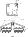
- FIG. 15 illustrates the version of the cable slack management module 10 discussed previously, where both of the trays 34 are being used for storing/managing cable slack 16, where one of the sliding adapter modules 14 receives connectorized cables 16 output from the lower tray 34a at a first level and the other sliding adapter module 14 receives connectorized cables 16 output from the upper tray 34b at a second level, wherein both of the levels are above the input plane 76 defined by the fan-out 20.
- FIGS. 16-17 illustrate the module set-up of FIG. 15 with the upper cover 42 applied.
- the cable slack management module 10 is designed to manage twenty-four 900 ⁇ m fibers that are input into the module 10 through a twenty-four fiber fan-out 20. As illustrated, the twenty-four fibers may be split into two groups of twelve fibers before exiting the module 10, wherein each group of twelve fibers may be lead to oppositely moving sliding adapter modules 14 (as shown in FIGS. 13-17 ) or adjacent stacked adapter modules 14 that move in the same direction.
- the cable slack management module 10 provides multiple set-up options.
- the chassis 12 depicted in FIGS. 1-4 is a 288-fiber chassis, with twenty-four sliding adapter modules 14 (i.e., two sets of twelve oppositely moving adapter modules 14), each adapter module 14 including twelve adapter ports.
- the fiber counts can be varied depending upon the desired density at both the input side (different fan-out devices) or at the output side.
Description
- This application is being filed on December 7, 2015 as a PCT International Patent Application and claims the benefit of
U.S. Patent Application Serial No. 62/090,203, filed on December 10, 2014 - The present invention relates to apparatus and methods for termination and storage of optical fiber cables, such as distribution cables.
- With respect to termination and storage of optical fibers including distribution fibers, various concerns exist. One concern is providing high density to minimize needed space. In the case of outside plant enclosures, a reduced size for the enclosures and the internal structures is preferred.
- A further concern related to termination and storage of optical fiber cables is the ease of access to the cables and the terminations. Such ease of use is desired during assembly, during installation in the field, and later when changes or modifications to the system are desired requiring adding or removing terminations, or when cleaning and checking the terminations.
- A further concern in the area of termination and storage of optical fiber cables includes protecting the optical fiber from damage from excess bending below the minimum bend radius of the cable. Such protection of the fibers is desired during assembly and installation, and later when individual terminations and cables are accessed for cleaning or modification.
- Prior art document
US 2014/259602 A1 discloses a telecommunications assembly including a tray assembly including a tray and a cable spool assembly rotatably mounted to the tray. The cable spool assembly includes a hub, a first flange engaged to the hub, and a second flange engaged to the hub opposite the first flange. A cable can be wound around the hub between the flanges for storage on the cable spool assembly. The second flange includes an outer surface. The outer surface includes a cable management area and a termination area disposed adjacent to the cable management area. One or more cassettes can be mounted to the termination region of the cable spool assembly for paying-out a cable patch cord. -
US 2011/268414 A1 discloses a multi-layer module that includes a multi-fiber cable storage layer having a cable entry opening and a cable winding structure. It further has a splice storage layer that is discrete from the multi-fiber cable storage layer and has a splice layer receiving opening in communication with the multi-fiber cable storage layer and a slack storage area. The multi-layer module may also include a pigtail storage layer that is discrete from both the multi-fiber cable storage layer and the splice storage layer, the pigtail storage layer having a pigtail connector area and a pigtail storage area, the pigtail storage area comprising a pigtail storage layer receiving opening in communication with the splice storage layer. -
US 2007/047894 A1 discloses telecommunications management devices having a plurality of cable management trays. The trays are selectively moveable out of an aligned arrangement in order to access the cables and terminations on each tray. Each tray includes a first cable access location for cables entering the tray, and a second cable access location for cables exiting the tray. A pivoting cover including mounting locations for cable terminations is provided on each tray. -
US 2013/287359 A1 discloses a payout cassette for a telecommunications cable. The telecommunications cable extends between a first end and a second end. The payout cassette pays-out the telecommunications cable when the first end of the telecommunications cable is pulled away from the payout cassette. The cassette also stores the telecommunications cable. The cassette includes a storage area and a transitioning area. The storage area is adapted to store a stored portion of the telecommunications cable. The transitioning area is adapted to transition the telecommunications cable from the stored portion within the storage area to a paid-out portion of the telecommunications cable that is external to the storage area. The transitioning area is at least partially positioned within an interior of the storage area. - Further improvements in the above mentioned areas are desired.
- The invention provides a fiber optic telecommunications system according to independent claim 1. Further embodiments are provided by the dependent claims.
- A variety of inventive aspects will be set forth in the description that follows. The inventive aspects can relate to individual features and combinations of features. It is to be understood that both the foregoing general description and the following detailed description are exemplary and explanatory only and are not restrictive of the broad inventive concepts upon which the embodiments disclosed herein are based.
-
-
FIG. 1 is a front perspective view of a telecommunications chassis including a plurality of cable slack management modules having inventive aspects in accordance with the present disclosure mounted thereon, according to the claimed invention; -
FIG. 2 is a rear perspective view of the chassis ofFIG. 1 ; -
FIG. 3 illustrates the chassis ofFIG. 1 with one of the cable slack management modules and a sliding adapter module of the chassis exploded off the chassis; -
FIG. 4 is a side view of the chassis ofFIGS. 1-3 illustrating the cable slack management modules mounted in a stacked configuration; -
FIG. 5 is a front perspective view of one of the cable slack management modules shown in isolation; -
FIG. 6 is a rear perspective view of the cable slack management module ofFIG. 5 ; -
FIG. 7 is a top view of the cable slack management module ofFIG. 5 ; -
FIG. 8 is a bottom view of the cable slack management module ofFIG. 5 ; -
FIG. 9 is a side view of the cable slack management module ofFIG. 5 ; -
FIG. 10 illustrates the cable slack management module ofFIG. 5 with the upper cover removed to show the internal features; -
FIG. 11 illustrates the cable slack management module ofFIG. 10 from a top view; -
FIG. 12 illustrates the cable slack management module ofFIG. 5 in an exploded configuration; -
FIG. 13 illustrates the cable slack management module being used as a direct pass-through distribution module, not forming part of the claimed invention, without the storage of extra cable slack; -
FIG. 14 illustrates the cable slack management module with only one of the trays of the module being used to store extra cable slack, not according to the claimed invention; -
FIG. 15 illustrates the cable slack management module with both of the trays of the module being used to store extra cable slack; -
FIG. 16 illustrates the cable slack management module ofFIG. 15 in a fully assembled configuration with the upper cover mounted thereon, wherein the output fibers are shown as being directed to sliding adapter modules; and -
FIG. 17 illustrates the cable slack management module ofFIG. 16 from a top view. - Referring now to
FIGS. 1-17 , a fiber optic cable slack management/storage module 10 is illustrated. InFIGS. 1-4 , a plurality of the cableslack management modules 10 is illustrated as mounted on a telecommunications fixture 12 (i.e., frame, chassis) in a stacked arrangement. The cableslack management modules 10 are mounted adjacent slidingadapter modules 14. The cableslack management modules 10 are configured to manage the cabling 16 (or cable slack) extending fromconnectors 18 coupled to theadapter modules 14. - As will be described in further detail, the cabled
fibers 16 terminated by theconnectors 18 coupled to the slidingadapter modules 14 are input into the cableslack management module 10 via an optical device 20 (e.g., a fan-out in the depicted embodiment). The configuration of the cableslack management module 10 allowsextra cable slack 16 to be stored therewithin such that theextra cable slack 16 can be used when thesliding adapter modules 14 are moved outwardly from thetelecommunications fixture 12, without violating minimum bending requirements. - Referring now to
FIGS. 5-17 , where one of the cableslack management modules 10 is illustrated in isolation, each cableslack management module 10 includes a base 22 with abottom wall 24 and vertically extendingperipheral walls 26. Thebase 22 defines a fan-outpocket 25 for receiving the fan-out 20 with a snap-fit interlock. The fan-outpocket 25 is defined partially by thebottom wall 24. The fan-outpocket 25 and the fan-out 20 define thefiber input portion 28 of the cableslack management module 10. - As shown in
FIGS. 7 ,8 ,11 , and17 , portions of the front and rearperipheral walls 26 of the base 22 defineflexible cantilever arms 30 for providing a snap-fit interlock with thetelecommunications fixture 12. - The
base 22 defines afirst spool 32 extending upwardly from thebottom wall 24 of thebase 22. As will be described in further detail hereafter, thefirst spool 32 is one of the structures that provide the minimum bend radius protection for thecables 16 within the cableslack management module 10. - As shown in
FIGS. 5-17 , each cableslack management module 10 also defines a pair of cable storage trays 34. The trays 34 are mounted in a stacked arrangement onto thebase 22 and define alower tray 34a and anupper tray 34b.Cables 16 enter the individual trays 34 via aramp 36 defined by each tray 34. After thefibers 16 are input into the cableslack management module 10 via the fan-out 20, half of the separated and cabledfibers 16 enter thelower tray 34a via theramp 36 of thelower tray 34a and half of the separated and cabledfibers 16 enter theupper tray 34b via theramp 36 of theupper tray 34b. - In the given embodiment of the cable
slack management module 10, theupper tray 34b (thefloor 38 thereof) forms thecover 40 of thelower tray 34a. Theupper tray 34b defines a separateremovable cover 42. The trays 34 are mounted via a snap-fit interlock to thebase 22. As shown inFIGS. 5 ,6 ,10 ,12 , and13-16 , aflexible portion 44 of both the frontperipheral wall 26 and the rearperipheral wall 26 of thebase 22 definesnotches 46 for receivingtabs 48 extending outwardly from the trays 34 for keeping the trays 34 mounted within thebase 22. - The
removable cover 42 of theupper tray 34b is also held in place by an inwardly extendingtab 50 of theflexible portion 44 of the rearperipheral wall 26 andflexible cantilever arms 52 defined by thefirst spool 32. In certain embodiments, thecover 42 used with theupper tray 34b may be provided with ahandle 54 to facilitate mounting and removal (seeFIGS. 5-7 ). - Each of the upper and lower trays 34 defines an
opening 56 through which thefirst spool 32 extends. Thus, thefirst spool 32 extends all the way from thebottom wall 24 to thecover 42 of theupper tray 34b. - Each tray 34 also includes a curved
peripheral wall 58, theinner face 60 of which defines asecond spool 62. Thesecond spool 62 defined by each tray 34 cooperates with thefirst spool 32 in keeping thecable slack 16 stored and managed without violating minimum bend radius requirements. - The second spool 62 (i.e., the
inner face 60 of the curvedperipheral wall 58 of each tray 34) is configured to contact thecables 16 within the tray 34 when thecables 16 are in a relaxed state (when the slidingadapter modules 14 are in a non-extended position). Anouter face 64 of thefirst spool 32 is configured to contact thecables 16 within the tray 34 when thecables 16 are pulled (when the slidingadapter modules 14 are moved to an extended position). - The combination of the
first spool 32 and thesecond spool 62 provides thecables 16 with bend radius protection both in a relaxed state and in a pulled, tensioned state. - Each tray 34 also defines a plurality of
cable retention fingers 66 extending inwardly from theperipheral wall 58. Thecable retention fingers 66 facilitate initial assembly of the cableslack management module 10 as thecables 16 are being lead from the fan-out 20, up theramps 36 and into the trays 34. In order to provide unobstructed movement of thecables 16 within the trays 34, however, thecable retention fingers 66 fit withinnotches 68 defined by thecover 42 for theupper tray 34b andnotches 70 defined by thefloor 38 of theupper tray 34b for thelower tray 34a. In this manner, a smooth, flush ceiling is created for each of the trays 34 and thecables 16 can move without any obstruction. - The
cable exit portion 72 of the cableslack management module 10 is defined adjacent thefirst spool 32 and at least partially by theinner face 60 of theperipheral wall 58 of each tray 34 (i.e., the second spool 62), where thecable exit 72 is generally defined by achannel 74 positioned between the first andsecond spools FIGS. 10 ,11 , and14-16 . Thecable exit portion 72 is generally aligned with thefiber input portion 28 of the cableslack management module 10 when viewing themodule 10 in a front to back direction. - Thus, the
optical fibers 16 enter the cableslack management module 10 via the fan-out 20 at a firstcommon plane 76. The separated and cabledfibers 16 are then directed to multiple levels defined by the trays 34 via theramps 36. Thecables 16 are looped once around the trays 34 and exit the cableslack management module 10 via thecable exit channel 74. It should be noted that in the depicted embodiment, half of the cabledfibers 16 coming from the fan-out 20 are directed into thelower tray 34a and half are directed into theupper tray 34b. - The
cables 16 exiting the cableslack management module 10 are terminated withfiber optic connectors 18 that are coupled to theadapters 17 of the slidingadapter modules 14. - Although shown with
LC format connectors 18, in other embodiments, thecables 16 output from the cableslack management module 10 may be terminated with other types or footprints ofconnectors 18 such as SC or LX.5,such connectors 18 leading toadapter modules 14 havingadapters 17 with matching footprints. - Examples of sliding
adapter modules 14 that are usable with the cableslack management module 10 of the present disclosure are shown and described in further detail inU.S. Patent Application Ser. No. 62/040,314, filed August 21, 2014 PCT Application No. PCT/US2015/046392, filed August 21, 2015 , both titled "High Density Adapter Carrier Pack;" andU.S. Patent Nos. 6,591,051 and9,075,203 - Now referring to
FIGS. 13-17 , even though the cableslack management module 10 has been described as being used as a cable slack storage/management device, thecable management module 10 can be set up to be used as a simple distribution or a fan-out module wherefibers 16 entering themodule 10 are output in a pass-through configuration, wherein one or more of the trays 34 are not used for carryingcoiled cables 16. - For example,
FIG 13 illustrates thecable management module 10 set up to output the cabledfibers 16 directly from themodule 10 without storing anyextra slack 16.Fibers 16 are input via the fan-out 20 and are output via anopening 78 at a front side of the base 22 that is at thesame plane 76 as the fan-out 20. -
FIG. 14 illustrates a set-up where only one of the trays 34 (e.g., thelower tray 34a) is used for storingcable slack 16. As shown in the depicted example, one of the slidingadapter modules 14 receivesconnectorized cables 16 that account for slack and the other of the slidingadapter modules 14 receivesconnectorized cables 16 directly from themodule 10 without any cable slack. -
FIG. 15 illustrates the version of the cableslack management module 10 discussed previously, where both of the trays 34 are being used for storing/managingcable slack 16, where one of the slidingadapter modules 14 receivesconnectorized cables 16 output from thelower tray 34a at a first level and the other slidingadapter module 14 receivesconnectorized cables 16 output from theupper tray 34b at a second level, wherein both of the levels are above theinput plane 76 defined by the fan-out 20. -
FIGS. 16-17 illustrate the module set-up ofFIG. 15 with theupper cover 42 applied. - In the depicted embodiment, the cable
slack management module 10 is designed to manage twenty-four 900µm fibers that are input into themodule 10 through a twenty-four fiber fan-out 20. As illustrated, the twenty-four fibers may be split into two groups of twelve fibers before exiting themodule 10, wherein each group of twelve fibers may be lead to oppositely moving sliding adapter modules 14 (as shown inFIGS. 13-17 ) or adjacentstacked adapter modules 14 that move in the same direction. The cableslack management module 10 provides multiple set-up options. - The
chassis 12 depicted inFIGS. 1-4 is a 288-fiber chassis, with twenty-four sliding adapter modules 14 (i.e., two sets of twelve oppositely moving adapter modules 14), eachadapter module 14 including twelve adapter ports. The fiber counts can be varied depending upon the desired density at both the input side (different fan-out devices) or at the output side. - Although in the foregoing description, terms such as "top," "bottom," "front," "back," "right," "left," "upper," and "lower" may have been used for ease of description and illustration, no restriction is intended by such use of the terms. The devices described herein can be used in any orientation, depending upon the desired application.
Claims (12)
- A fiber optic telecommunications system comprising:a plurality of fiber optic connectors (18) terminating a plurality of cables (16);a cable slack management module (10) including a base (22) configured for managing the cables (16) that have been terminated to the fiber optic connectors (18), wherein the fiber optic connectors (18) are positioned such that the fiber optic connectors (18) can move relative to the base (22), the base (22) further defining a first cable management spool (32) an outer face of which is configured to contact the cables (16) when the cables (16) are pulled away from the base (22);a second cable management spool (62), within which the first cable management spool (32) is located, wherein an inner face of the second cable management spool (62) is configured to contact the cables (16) when the cables (16) are in a relaxed, non-pulled state, wherein the fiber optic cable slack management module (10) defines a cable exit (72) adjacent the first cable management spool (32) and defined at least partially by the second cable management spool (62), the cable exit (72) defined by a channel (74) positioned between the first and second cable management spools (32, 62); anda plurality of removable trays (34) mounted to the base (22) in a stacked configuration, each of the trays (34) configured for managing cables (16), wherein an inner face (60) of an outer peripheral wall (58) of each tray (34) defines the second cable management spool (62), wherein the cables (16) terminated by the fiber optic connectors (18) are provided within the cable slack management module (10) such that the cables (16) transition from a common plane when entering the base (22) of the cable slack management module (10) to a plurality of different levels provided by the stacked trays (34), wherein the cables (16) terminated by the fiber optic connectors (18) are provided within the cable slack management module (10) such that the cables (16) are looped once around within the trays (34), wherein the cable exit (72) is defined both adjacent the first cable management spool (32) and at least partially by the inner face (60) of the outer peripheral wall (58) of each tray (34), wherein the cable slack management module (10) defines a cable input (28) at a rear of the base (22) and wherein the cable exit (72) is defined at a front of the base (22) , wherein the cable input (28) and the cable exit (72) are generally aligned when viewed in a front-to-back direction, wherein each of the trays (34) defines a ramp (36) for transitioning the cables (16) within the cable slack management module (10) from the common plane when entering the base (22) to the different levels provided by the stacked trays (34), the ramps (36) of the trays (34) being adjacent the first cable management spool (32) and the cable exit (72) of the cable slack management module (10).
- A fiber optic telecommunications system according to claim 1, further comprising two of the trays (34).
- A fiber optic telecommunications system according to claim 1, wherein an input (28) for the cable slack management module (10) is defined by a fiber optic fan-out (20).
- A fiber optic telecommunications system according to claim 1, wherein each tray (34) defines a smooth, flush ceiling so as to allow unobstructed movement of the cables (16) between a relaxed, non-pulled state and a pulled state.
- A fiber optic telecommunications system according to claim 4, wherein each tray (34) defines cable retention fingers (66) extending inwardly from the outer peripheral wall (58), the retention fingers (66) fitting within notches (68, 70) defined by a cover (38, 40, 42) for each tray (34) so as to define the smooth, flush ceiling.
- A fiber optic telecommunications system according to claim 5, wherein the cover (40) for at least one of the trays (34a) is defined by a floor (38) of an adjacent upper tray (34b).
- A fiber optic telecommunications system according to claim 1, further comprising snap-fit features (30) for removably mounting the cable slack management module (10) to a telecommunications fixture (12).
- A fiber optic telecommunications system according to claim 1, further comprising:a telecommunications chassis (12) including at least one movable adapter module (14)mounted to the chassis;at least one cable slack management module (10) mounted to the chassis adjacent the at least one movable adapter module (14), the at least one cable slack management module (10) configured to manage cables (16) extending from the fiber optic connectors (18) that are coupled to adapters (17) of the at least one movable adapter module (14).
- A fiber optic telecommunications system according to claim 8, further comprising a plurality of cable slack management modules (10) mounted to the chassis in a stacked arrangement.
- A fiber optic telecommunications system according to claim 8, wherein the chassis includes one cable slack management module (10) for every two movable adapter modules (14).
- A fiber optic telecommunications system according to claim 8, wherein the at least one movable adapter module (14) includes LC format fiber optic adapters (17).
- A fiber optic telecommunications system according to claim 8, wherein an input (28) for the at least one cable slack management module (10) is defined by a fiber optic fan-out (20) that separates ribbonized fibers (16) into individual cabled fibers (16) leading to the fiber optic connectors (18) coupled to the adapters (17) of the at least one movable adapter module (14), wherein portions of the cabled fibers (16) are positioned and managed within the at least one cable slack management module (10).
Applications Claiming Priority (2)
| Application Number | Priority Date | Filing Date | Title |
|---|---|---|---|
| US201462090203P | 2014-12-10 | 2014-12-10 | |
| PCT/US2015/064345 WO2016094331A1 (en) | 2014-12-10 | 2015-12-07 | Fiber optic cable slack management module |
Publications (3)
| Publication Number | Publication Date |
|---|---|
| EP3230780A1 EP3230780A1 (en) | 2017-10-18 |
| EP3230780A4 EP3230780A4 (en) | 2018-07-25 |
| EP3230780B1 true EP3230780B1 (en) | 2023-10-25 |
Family
ID=56108027
Family Applications (1)
| Application Number | Title | Priority Date | Filing Date |
|---|---|---|---|
| EP15867719.5A Active EP3230780B1 (en) | 2014-12-10 | 2015-12-07 | Fiber optic cable slack management module |
Country Status (3)
| Country | Link |
|---|---|
| US (3) | US10247886B2 (en) |
| EP (1) | EP3230780B1 (en) |
| WO (1) | WO2016094331A1 (en) |
Families Citing this family (6)
| Publication number | Priority date | Publication date | Assignee | Title |
|---|---|---|---|---|
| US10409020B2 (en) * | 2013-04-24 | 2019-09-10 | CommScope Connectivity Belgium BVBA | Universal mounting mechanism for mounting a telecommunications chassis to a telecommunciations fixture |
| US11009670B2 (en) | 2017-02-23 | 2021-05-18 | Commscope Technologies Llc | High fiber count termination device |
| CN109696732B (en) * | 2017-10-24 | 2022-12-09 | 康普技术有限责任公司 | Optical fiber management device |
| WO2020214817A1 (en) * | 2019-04-17 | 2020-10-22 | Commscope Technologies Llc | Telecommunications cable guide |
| JP7154413B2 (en) * | 2019-07-04 | 2022-10-17 | 三菱電機株式会社 | Electronics |
| US11493717B2 (en) | 2020-07-31 | 2022-11-08 | Google Llc | Fiber optic cable distribution and management system |
Family Cites Families (204)
| Publication number | Priority date | Publication date | Assignee | Title |
|---|---|---|---|---|
| US2864656A (en) | 1954-06-25 | 1958-12-16 | Yorinks Alexander | Slide mechanism |
| NL193890A (en) | 1954-12-27 | |||
| US3901564A (en) | 1973-10-29 | 1975-08-26 | Henry P Armstrong | Drawer extensible slide chassis |
| US4070076A (en) | 1977-05-05 | 1978-01-24 | The Raymond Lee Organization, Inc. | Drawer sliding device |
| DE2735106C2 (en) | 1977-08-04 | 1983-09-01 | AEG-Telefunken Nachrichtentechnik GmbH, 7150 Backnang | Cable set for a telecommunication cable |
| US4172625A (en) | 1977-12-15 | 1979-10-30 | Comerco, Inc. | Drawer extenders |
| DE2918572A1 (en) | 1978-06-13 | 1980-01-03 | Blum Gmbh Julius | EXTENSION GUIDE SET FOR DRAWERS |
| DE2918309C2 (en) | 1979-05-07 | 1982-11-04 | Heino Schulz Kunststoffverarbeitung, 5300 Bonn | Drawer pull-out device |
| US4359262A (en) | 1980-06-30 | 1982-11-16 | Northern Telecom Limited | Tray for organizing optical fiber splices and enclosures embodying such trays |
| US4373776A (en) | 1980-06-30 | 1983-02-15 | Northern Telecom Limited | Protection case for optical fiber splices |
| JPS58109707U (en) | 1982-01-19 | 1983-07-26 | 日本電気株式会社 | Terminal board storage device |
| FR2531544B1 (en) | 1982-08-04 | 1985-01-25 | Cit Alcatel | OPTICAL CABLE HEAD |
| FR2531576A1 (en) | 1982-08-04 | 1984-02-10 | Cit Alcatel | Optoelectronic connecting and interface frame. |
| JPS5974523A (en) | 1982-10-21 | 1984-04-27 | Furukawa Electric Co Ltd:The | Optical fiber connection box |
| FR2538918A1 (en) | 1983-01-05 | 1984-07-06 | Telecommunications Sa | FIBER OPTIC CONNECTION AND BREWING BOX |
| DE3308682C2 (en) | 1983-03-11 | 1985-12-05 | Krone Gmbh, 1000 Berlin | Matrix main distributor |
| US4494806A (en) | 1983-05-13 | 1985-01-22 | Leslie Metal Arts Company | Spring loaded drawer assembly with mechanical damping |
| US4595255A (en) | 1983-08-24 | 1986-06-17 | Fiberlan, Inc. | Optical fiber wiring center |
| FR2556895B1 (en) | 1983-12-20 | 1986-12-19 | Lignes Telegraph Telephon | DEVICE FOR CONNECTING CABLES, PARTICULARLY WITH OPTICAL FIBERS |
| DE3347621A1 (en) | 1983-12-30 | 1985-07-11 | Wilhelm Sedlbauer GmbH Fabrik für Feinmechanik und Elektronik, 8000 München | DISTRIBUTION RACK FOR FIBERGLASS CABLE ENDS |
| JPS60169811A (en) | 1984-02-14 | 1985-09-03 | Furukawa Electric Co Ltd:The | Containing device for connection excessive length of optical fiber |
| GB2138057B (en) | 1984-04-11 | 1987-09-30 | Tekken Constr Co | Method of building strengthened, embanked foundation |
| US4630886A (en) | 1984-04-16 | 1986-12-23 | At&T Bell Laboratories | Lightguide distributing unit |
| JPS6155607A (en) | 1984-08-28 | 1986-03-20 | Fujitsu Ltd | Light distributing board |
| JPS6190104A (en) | 1984-10-09 | 1986-05-08 | Nec Corp | Installing structure for optical adapter |
| CA1249741A (en) | 1984-10-25 | 1989-02-07 | Michael J. Donaldson | Optical cable terminating equipment |
| FR2575020B1 (en) | 1984-12-14 | 1987-02-13 | Nozick Jacques | DISTRIBUTOR FOR OPTICAL CABLES |
| US4699455A (en) | 1985-02-19 | 1987-10-13 | Allen-Bradley Company | Fiber optic connector |
| DE3511653A1 (en) | 1985-03-29 | 1986-10-02 | Siemens AG, 1000 Berlin und 8000 München | BASE WITH INSERT FOR A COUPLING PANEL BETWEEN FIBERGLASS CABLES |
| US4765710A (en) | 1985-07-30 | 1988-08-23 | Siemens Aktiengesellschaft | Distributing frame for optical waveguides and the like |
| FR2587127B1 (en) | 1985-09-06 | 1987-10-23 | Valleix Paul | STRUCTURE FOR OPTICAL CONNECTIONS |
| US4792203A (en) | 1985-09-17 | 1988-12-20 | Adc Telecommunications, Inc. | Optical fiber distribution apparatus |
| US4737039A (en) | 1986-12-08 | 1988-04-12 | Knape & Vogt Manufacturing Company | Drawer rail carrier roller mount |
| US4840449A (en) | 1988-01-27 | 1989-06-20 | American Telephone And Telegraph Company, At&T Bell Laboratories | Optical fiber splice organizer |
| US4820007A (en) | 1988-02-12 | 1989-04-11 | American Telephone And Telegraph Company At&T Bell Laboratories | Cable closure and methods of assembling |
| US4898448A (en) | 1988-05-02 | 1990-02-06 | Gte Products Corporation | Fiber distribution panel |
| US4900123A (en) | 1988-08-29 | 1990-02-13 | Gte Products Corporation | 1550 nm fiber distribution panel |
| DE3836273C2 (en) | 1988-10-25 | 1997-05-07 | Standard Praezision Gmbh | Synchronized three-part telescopic rail for tension members |
| DE3838428A1 (en) | 1988-11-12 | 1990-05-31 | Philips Patentverwaltung | SWITCH DISTRIBUTOR FOR THE PRODUCTION OF FREELY SELECTABLE OPTICAL CONNECTORS |
| US5071211A (en) | 1988-12-20 | 1991-12-10 | Northern Telecom Limited | Connector holders and distribution frame and connector holder assemblies for optical cable |
| US5013121A (en) | 1989-06-29 | 1991-05-07 | Anton Mark A | Optical fiber storage container |
| US5067678A (en) | 1989-07-31 | 1991-11-26 | Adc Telecommunications, Inc. | Optic cable management system |
| US4995688A (en) | 1989-07-31 | 1991-02-26 | Adc Telecommunications, Inc. | Optical fiber distribution frame |
| US5316243A (en) | 1989-07-31 | 1994-05-31 | Adc Telecommunications, Inc. | Optic cable management |
| US4986762A (en) | 1989-08-15 | 1991-01-22 | Minnesota Mining And Manufacturing Company | Termination module for use in an array of modules |
| US4971421A (en) | 1989-09-29 | 1990-11-20 | Reliance Comm/Tec Corporation | Fiber optic splice and patch enclosure |
| US5142606A (en) | 1990-01-22 | 1992-08-25 | Porta Systems Corp. | Optical fiber cable distribution frame and support |
| US5100221A (en) | 1990-01-22 | 1992-03-31 | Porta Systems Corp. | Optical fiber cable distribution frame and support |
| FR2660077B1 (en) | 1990-03-20 | 1993-08-20 | Loh Rittal Werk Gmbh Co | CONNECTION BOX FOR FIBER OPTICS. |
| US5174675A (en) | 1990-05-07 | 1992-12-29 | Inventio Ag | Guide bar for an elevator door |
| FR2663917B1 (en) | 1990-06-29 | 1993-06-04 | Cit Alcatel | MODULAR DEVICE FOR STORING RESERVES OF TRANSMISSION SUPPORT ON LINKS, PARTICULARLY FIBER OPTIC. |
| US5066149A (en) | 1990-09-11 | 1991-11-19 | Adc Telecommunications, Inc. | Splice tray with slack take-up |
| DE69124902T2 (en) | 1990-10-04 | 1997-06-19 | Alcatel Cable Interface | Cassette for optical connections |
| US5138688A (en) | 1990-11-09 | 1992-08-11 | Northern Telecom Limited | Optical connector holder assembly |
| US5127082A (en) | 1991-03-22 | 1992-06-30 | The Siemon Company | Fiber optic patch panel |
| US5129030A (en) | 1991-05-30 | 1992-07-07 | At&T Bell Laboratories | Movable lightguide connector panel |
| FR2678076B1 (en) | 1991-06-20 | 1994-09-23 | Cit Alcatel | MODULE FOR STORING A TRANSMISSION SUPPORT RESERVE ON A LINK, PARTICULARLY WITH OPTICAL FIBER AND STORAGE DEVICE COMPRISING A SET OF SUCH MODULES. |
| DE4133375C1 (en) | 1991-10-05 | 1993-04-22 | Krone Ag | |
| FR2682488B1 (en) | 1991-10-15 | 1994-01-21 | Bruno Capelle | MODULAR CABLES HEAD WITH LARGE CAPACITY FIBER OPTICS. |
| ES1019586Y (en) | 1991-12-12 | 1992-11-01 | Telefonica De Espana, S.A. | TERMINAL JOINT AND MODULAR OPTICAL DISTRIBUTION. |
| US5247603A (en) | 1992-01-24 | 1993-09-21 | Minnesota Mining And Manufacturing Company | Fiber optic connection system with exchangeable cross-connect and interconnect cards |
| FR2687744B1 (en) | 1992-02-21 | 1994-04-08 | Mars Actel | SET OF ARTICULATED FLAT MODULES. |
| FR2687800B1 (en) | 1992-02-21 | 1994-04-08 | Mars Actel | ADAPTABLE CASSETTE FOR LOVING AND SPLICING OPTICAL FIBERS. |
| US5202942A (en) | 1992-04-03 | 1993-04-13 | Amp Incorporated | Cable termination member for fiber optic connectors having improved strain relief |
| US5275064A (en) | 1992-06-12 | 1994-01-04 | General Devices Co., Inc. | Extensible platform with cable drive system |
| US5240209A (en) | 1992-11-17 | 1993-08-31 | Telect, Inc. | Telecommunication multiple cable carrier |
| US5323480A (en) | 1992-11-25 | 1994-06-21 | Raychem Corporation | Fiber optic splice closure |
| US5335349A (en) | 1992-12-14 | 1994-08-02 | Telect, Inc. | Telecommunication overhead cable distribution assembly |
| FR2703160B1 (en) | 1993-03-26 | 1995-06-02 | Corning Inc | Cassette for optical fiber device, fitted with a bundle of flexible fiber protection tubes. |
| US5363467A (en) | 1993-05-28 | 1994-11-08 | Minnesota Mining And Manufacturing Company | Compact fiber optic housing |
| US5339379A (en) | 1993-06-18 | 1994-08-16 | Telect, Inc. | Telecommunication fiber optic cable distribution apparatus |
| US5412751A (en) | 1993-08-31 | 1995-05-02 | The Siemon Company | Retrofittable multimedia patch management system |
| GB9318633D0 (en) | 1993-09-08 | 1993-10-27 | Raychem Sa Nv | Organization of optical fibres |
| US5353367A (en) | 1993-11-29 | 1994-10-04 | Northern Telecom Limited | Distribution frame and optical connector holder combination |
| US5490229A (en) | 1993-12-08 | 1996-02-06 | At&T Ipm Corp. | Slidably mounted optical fiber distribution tray |
| TW232757B (en) | 1994-01-21 | 1994-10-21 | Adc Telecommunications Inc | High-density fiber distribution frame |
| US5402515A (en) | 1994-03-01 | 1995-03-28 | Minnesota Mining And Manufacturing Company | Fiber distribution frame system, cabinets, trays and fiber optic connector couplings |
| DE4413136C1 (en) | 1994-04-19 | 1995-05-04 | Loh Kg Rittal Werk | Optical-fibre splice box |
| US5511144A (en) | 1994-06-13 | 1996-04-23 | Siecor Corporation | Optical distribution frame |
| GB2292466B (en) | 1994-08-15 | 1997-09-10 | Pirelli General Plc | Guiding optical fibres in ducts |
| US5530783A (en) | 1994-08-31 | 1996-06-25 | Berg Technology, Inc. | Backplane optical fiber connector for engaging boards of different thicknesses and method of use |
| EP0730748A1 (en) | 1994-09-28 | 1996-09-11 | Telephone Cables Limited | A splice tray |
| US5509096A (en) | 1994-10-28 | 1996-04-16 | Syntec Inc. | Receptacle and plug fiber optic connector assembly |
| DE4442823A1 (en) | 1994-12-01 | 1996-06-05 | Siemens Ag | Cassette module for optical fibers |
| DE29504191U1 (en) | 1995-03-01 | 1996-03-28 | Krone Ag | Insert for receiving devices of the LWL technology |
| US5613030A (en) | 1995-05-15 | 1997-03-18 | The Whitaker Corporation | High density fiber optic interconnection enclosure |
| US5724469A (en) | 1996-01-26 | 1998-03-03 | Ortronics, Inc. | Adjustable fiber storage plate |
| US5836148A (en) | 1996-02-06 | 1998-11-17 | Kunimorikagaku Ltd. | Cable chain |
| US5811055A (en) | 1996-02-06 | 1998-09-22 | Geiger; Michael B. | Torch mounted gas scavaging system for manual and robotic welding and cutting torches |
| DE19611770C2 (en) | 1996-03-14 | 1998-04-09 | Krone Ag | Manageable splice cassette |
| DE69713544T2 (en) | 1996-04-12 | 2003-02-20 | Telephone Cables Ltd | Arrangement of an optical fiber |
| ES2201235T3 (en) | 1996-10-07 | 2004-03-16 | Julius Blum Gesellschaft M.B.H. | EXTRACTION GUIDE GAME FOR DRAWERS. |
| WO1998041891A1 (en) | 1997-03-17 | 1998-09-24 | Tii Industries, Inc. | Fiber optic cable bend radius controller |
| US5802237A (en) | 1997-04-18 | 1998-09-01 | Minnesota Mining And Manufacturing Company | Optical fiber organizer |
| US6022150A (en) | 1997-04-30 | 2000-02-08 | The Whitaker Corporation | Fiber optic connector |
| US6128946A (en) | 1997-06-26 | 2000-10-10 | Crane Nuclear, Inc. | Method and apparatus for on-line detection of leaky emergency shut down or other valves |
| US5975769A (en) | 1997-07-08 | 1999-11-02 | Telect, Inc. | Universal fiber optic module system |
| US5971626A (en) | 1997-08-29 | 1999-10-26 | Siecor Corporation | Fiber optic connector and connector sleeve assembly |
| US6009224A (en) | 1997-11-06 | 1999-12-28 | Allen; Barry Wayne | Fiber optic organizer with lockable trays and method of accessing a tray |
| US5923753A (en) | 1997-11-17 | 1999-07-13 | Adc Telecommunications, Inc. | Optic cable exit trough with bypass |
| US5946440A (en) | 1997-11-17 | 1999-08-31 | Adc Telecommunications, Inc. | Optical fiber cable management device |
| US6027252A (en) | 1997-12-19 | 2000-02-22 | The Whitaker Corporation | Simplified fiber optic receptacle |
| US5966492A (en) | 1997-12-19 | 1999-10-12 | Antec Corporation | Apparatus for storing and splicing optical fibers |
| US5978540A (en) | 1998-04-23 | 1999-11-02 | Antec Corporation | Apparatus for interconnecting optical fibers |
| US6208796B1 (en) | 1998-07-21 | 2001-03-27 | Adc Telecommunications, Inc. | Fiber optic module |
| FR2782171B1 (en) | 1998-08-04 | 2001-11-30 | Pouyet Sa | FIBER OPTIC CABLES CONNECTION DEVICE |
| US6076908A (en) | 1998-09-17 | 2000-06-20 | Platt And Labonia Co. | Drawer for storage cabinet |
| US6215938B1 (en) | 1998-09-21 | 2001-04-10 | Adc Telecommunications, Inc. | Fiber optic cabinet and tray |
| US6496638B1 (en) | 1998-10-23 | 2002-12-17 | Lucent Technologies Inc. | Optical fiber cassette |
| US6760531B1 (en) | 1999-03-01 | 2004-07-06 | Adc Telecommunications, Inc. | Optical fiber distribution frame with outside plant enclosure |
| US6236795B1 (en) | 1999-06-07 | 2001-05-22 | E. Walter Rodgers | High-density fiber optic cable distribution frame |
| US6226436B1 (en) | 1999-11-18 | 2001-05-01 | Lucent Technologies, Inc. | Fiber optical pedestal |
| DE19956067A1 (en) | 1999-11-22 | 2001-05-23 | Rxs Kabelgarnituren Gmbh & Co | Cassette for accommodating optical fibres, surplus lengths, splices, etc., has differently shaped splice holders for various types of splice protection elements, and add-on elements for adapting to required use |
| US6504988B1 (en) | 2000-01-24 | 2003-01-07 | Adc Telecommunications, Inc. | Cable management panel with sliding drawer |
| US6438310B1 (en) | 2000-01-24 | 2002-08-20 | Adc Telecommunications, Inc. | Cable management panel with sliding drawer |
| US6301424B1 (en) | 2000-04-13 | 2001-10-09 | Lucent Technologies Inc. | Distribution frame cable routing apparatus |
| US6439523B1 (en) | 2000-06-02 | 2002-08-27 | Panduit Corp. | Universal mounting system for a fiber optic management center |
| US6360050B1 (en) | 2000-09-08 | 2002-03-19 | Telect, Inc. | High density fiber distribution tray system |
| US6845207B2 (en) | 2001-02-12 | 2005-01-18 | Fiber Optic Network Solutions Corp. | Optical fiber enclosure system |
| US6600866B2 (en) | 2001-03-13 | 2003-07-29 | 3M Innovative Properties Company | Filament organizer |
| GB0108255D0 (en) | 2001-04-02 | 2001-05-23 | Tyco Electronics Raychem Nv | Optical fibre organiser |
| US6792190B2 (en) | 2001-06-01 | 2004-09-14 | Telect, Inc. | High density fiber optic splitter/connector tray system |
| US7079744B2 (en) | 2001-07-06 | 2006-07-18 | Adc Telecommunications, Inc. | Cable management panel with sliding drawer and methods |
| US6594434B1 (en) | 2001-10-26 | 2003-07-15 | Ciena Corporation | Fiber optic cables management and measurement apparatus |
| FR2832225B1 (en) | 2001-11-13 | 2004-08-27 | Nexans | HIGH DENSITY OPTICAL DISTRIBUTOR AND METHOD FOR THE GARAGE OF SUCH A DISTRIBUTOR |
| FR2832226B1 (en) | 2001-11-13 | 2004-10-22 | Nexans | OPTICAL FIBER DISTRIBUTION AND CONNECTION MODULE FOR AN OPTICAL DISTRIBUTOR |
| US6591051B2 (en) | 2001-11-16 | 2003-07-08 | Adc Telecommunications, Inc. | Fiber termination block with angled slide |
| DE20200065U1 (en) | 2002-01-03 | 2003-03-06 | Ccs Technology Inc | Splice cassette |
| FR2836560B1 (en) | 2002-02-25 | 2004-06-18 | Nexans | LOVING CASSETTE FOR OPTICAL FIBERS |
| US6909833B2 (en) | 2002-03-15 | 2005-06-21 | Fiber Optic Network Solutions, Inc. | Optical fiber enclosure system using integrated optical connector and coupler assembly |
| US7116777B2 (en) | 2002-04-05 | 2006-10-03 | Adc Telecommunications, Inc. | Termination frame with modules and method |
| CN100374892C (en) | 2002-04-12 | 2008-03-12 | 泰科电子雷伊化学有限公司 | Optical circuit enclosure |
| MY131063A (en) | 2002-05-17 | 2007-07-31 | Harn Marketing Sdn Bhd | Guide rails pull-out drawer/equipment |
| US6715619B2 (en) | 2002-07-22 | 2004-04-06 | Adc Telecommunications, Inc. | Fiber management drawer and patch panel |
| US6677520B1 (en) | 2002-07-22 | 2004-01-13 | Adc Telecommunications, Inc. | Fanning tray |
| US6748155B2 (en) | 2002-07-22 | 2004-06-08 | Adc Telecommunications, Inc. | Fiber management drawer and sliding cable slack limiter |
| DE60322242D1 (en) | 2002-10-11 | 2008-08-28 | 3M Innovative Properties Co | DRAWER FOR HANDLING OPTICAL FIBERS |
| US6804447B2 (en) | 2002-11-05 | 2004-10-12 | Adc Telecommunications, Inc. | Fiber panel with integrated couplers |
| DE10255561A1 (en) | 2002-11-22 | 2004-06-09 | Krone Gmbh | Method and device for coupling optical fibers |
| US6768860B2 (en) | 2002-12-05 | 2004-07-27 | Jds Uniphase Inc. | High density fiber optic module |
| US6865331B2 (en) | 2003-01-15 | 2005-03-08 | Adc Telecommunications, Inc. | Rotating radius limiter for cable management panel and methods |
| US6809258B1 (en) | 2003-02-24 | 2004-10-26 | Cisco Technology, Inc. | Apparatus for cable routing management |
| US6853795B2 (en) | 2003-03-05 | 2005-02-08 | Corning Cable Systems Llc | High density fiber optic distribution frame |
| US7171099B2 (en) | 2003-07-31 | 2007-01-30 | Adc Telecommunications, Inc. | Slide arrangement for cable drawer |
| KR200337929Y1 (en) | 2003-10-23 | 2004-01-13 | 허필규 | A Housing for purchase of optical fiber adapter |
| US6920274B2 (en) | 2003-12-23 | 2005-07-19 | Adc Telecommunications, Inc. | High density optical fiber distribution frame with modules |
| US7315681B2 (en) | 2004-08-09 | 2008-01-01 | Anthony Kewitsch | Fiber optic rotary coupling and devices |
| US7171100B2 (en) | 2004-11-03 | 2007-01-30 | Adc Telecommunications, Inc. | Optical fiber slack storage tray for distribution cabinet |
| US7376323B2 (en) | 2005-05-25 | 2008-05-20 | Adc Telecommunications, Inc. | Fiber optic adapter module |
| US7460758B2 (en) | 2005-06-03 | 2008-12-02 | Telect Inc. | Fiber management system |
| US20070003204A1 (en) | 2005-06-30 | 2007-01-04 | Elli Makrides-Saravanos | Methods and apparatus for splitter modules and splitter module housings |
| US7406240B2 (en) | 2005-07-21 | 2008-07-29 | Ortronics, Inc. | Patch panel for fiber optic network |
| US7416349B2 (en) | 2005-07-27 | 2008-08-26 | Adc Telecommunications, Inc. | Fiber optic adapter module |
| US7397996B2 (en) | 2005-08-02 | 2008-07-08 | Adc Telecommunications, Inc. | Cable management panel with rear entry |
| US7352945B2 (en) * | 2005-08-29 | 2008-04-01 | Adc Telecommunications, Inc. | Outside plant enclosure with pivoting fiber trays |
| US7302153B2 (en) | 2005-10-26 | 2007-11-27 | Telect Inc. | Fiber management access system |
| WO2007067722A2 (en) | 2005-12-08 | 2007-06-14 | Lenel Systems International, Inc. | System and method for detecting an invalid camera in video surveillance |
| US7409137B2 (en) | 2006-10-04 | 2008-08-05 | Adc Telecommunications, Inc. | Slide arrangement for cable drawer |
| US7689089B2 (en) | 2006-10-11 | 2010-03-30 | Panduit Corp. | Release latch for pre-terminated cassette |
| US7496268B2 (en) | 2006-12-13 | 2009-02-24 | Corning Cable Systems Llc | High density fiber optic hardware |
| US7493002B2 (en) | 2007-01-19 | 2009-02-17 | Adc Telecommunications, Inc. | Fiber optic adapter cassette and panel |
| US8861918B2 (en) | 2007-09-07 | 2014-10-14 | Corning Cable Systems Llc | Fiber optic adapter module and tray |
| US7945138B2 (en) | 2007-10-01 | 2011-05-17 | Clearfield, Inc. | Modular optical fiber cassette |
| US8059932B2 (en) | 2007-10-01 | 2011-11-15 | Clearfield, Inc. | Modular optical fiber cassette |
| US7751674B2 (en) | 2007-10-01 | 2010-07-06 | Clearfield, Inc. | Modular optical fiber cassettes and fiber management methods |
| CN101836148B (en) * | 2007-10-22 | 2014-04-16 | Adc电信公司 | Fiber distribution hub |
| US7747125B1 (en) | 2007-11-07 | 2010-06-29 | Alliance Fiber Optic Products, Inc. | Structured fiber optic cassette with multi-furcated cable access |
| US20090196563A1 (en) | 2008-02-01 | 2009-08-06 | Mullsteff David M | Multi-Fiber Optical Patch Cord Breakout Assembly |
| US7889961B2 (en) | 2008-03-27 | 2011-02-15 | Corning Cable Systems Llc | Compact, high-density adapter module, housing assembly and frame assembly for optical fiber telecommunications |
| US7764859B2 (en) | 2008-03-28 | 2010-07-27 | Adc Telecommunications, Inc. | Universal cable management panel |
| US7715681B2 (en) | 2008-03-28 | 2010-05-11 | Adc Telecommunications, Inc. | Rear latch arrangement for sliding drawer |
| US7978951B2 (en) | 2008-03-28 | 2011-07-12 | Adc Telecommunications, Inc. | Bulkhead with angled openings and method |
| US7876993B2 (en) | 2008-05-05 | 2011-01-25 | Adc Telecommunications, Inc. | Drawer arrangement with rack and pinion |
| US8290333B2 (en) | 2008-08-29 | 2012-10-16 | Corning Cable Systems Llc | Fiber optic cable assemblies with furcation bodies having features for manufacturing and methods of making the same |
| US8285104B2 (en) | 2008-08-29 | 2012-10-09 | Corning Cable Systems Llc | Clip for securing a fiber optic cable assembly and associated assemblies |
| US7856166B2 (en) | 2008-09-02 | 2010-12-21 | Corning Cable Systems Llc | High-density patch-panel assemblies for optical fiber telecommunications |
| KR20100027636A (en) * | 2008-09-03 | 2010-03-11 | 에스케이브로드밴드주식회사 | Multi-user optical fiber distribution case |
| CA2741656C (en) | 2008-10-27 | 2020-07-07 | Corning Cable Systems Llc | Variably configurable and modular local convergence point |
| US8879882B2 (en) | 2008-10-27 | 2014-11-04 | Corning Cable Systems Llc | Variably configurable and modular local convergence point |
| US8428418B2 (en) | 2008-12-09 | 2013-04-23 | Adc Telecommunications, Inc. | Fiber optic adapter plate and cassette |
| EP2380054A1 (en) | 2009-01-15 | 2011-10-26 | ADC Telecommunications, INC. | Fiber optic module, chassis and adapter |
| US8380036B2 (en) | 2009-01-20 | 2013-02-19 | Adc Telecommunications, Inc. | Splitter module with connectorized pigtail manager |
| US9075216B2 (en) | 2009-05-21 | 2015-07-07 | Corning Cable Systems Llc | Fiber optic housings configured to accommodate fiber optic modules/cassettes and fiber optic panels, and related components and methods |
| US8712206B2 (en) * | 2009-06-19 | 2014-04-29 | Corning Cable Systems Llc | High-density fiber optic modules and module housings and related equipment |
| US7945136B2 (en) | 2009-06-19 | 2011-05-17 | Corning Cable Systems Llc | Mounting of fiber optic cable assemblies within fiber optic shelf assemblies |
| ES2403007A1 (en) | 2009-07-01 | 2013-05-13 | Adc Telecommunications, Inc | Wall-mounted fiber distribution hub |
| US8801296B2 (en) | 2010-02-02 | 2014-08-12 | Adc Telecommunications, Inc. | Fiber optic cable bundle with staggered connectors |
| CA2789356A1 (en) | 2010-02-12 | 2011-08-18 | Adc Telecommunications, Inc. | Communications bladed panel systems |
| JP5778696B2 (en) | 2010-02-12 | 2015-09-16 | エーディーシー テレコミュニケーションズ,インコーポレイティド | Managed fiber connection system |
| US9519118B2 (en) | 2010-04-30 | 2016-12-13 | Corning Optical Communications LLC | Removable fiber management sections for fiber optic housings, and related components and methods |
| US20110268408A1 (en) | 2010-04-30 | 2011-11-03 | Giraud William J | Door fiber management for fiber optic housings, and related components and methods |
| US8660397B2 (en) * | 2010-04-30 | 2014-02-25 | Corning Cable Systems Llc | Multi-layer module |
| US8705926B2 (en) | 2010-04-30 | 2014-04-22 | Corning Optical Communications LLC | Fiber optic housings having a removable top, and related components and methods |
| BR112012032724A2 (en) | 2010-06-23 | 2016-11-29 | Adc Telecommunications Inc | telecommunications set |
| US8600208B2 (en) | 2010-08-24 | 2013-12-03 | Adc Telecommunications, Inc. | Fiber optic telecommunications module |
| WO2013105998A2 (en) | 2011-02-16 | 2013-07-18 | Tyco Electronics Corporation | Fiber optic closure |
| CN103917904A (en) | 2011-10-07 | 2014-07-09 | Adc电信公司 | Fiber optic cassette, system, and method |
| US9170391B2 (en) | 2011-10-07 | 2015-10-27 | Adc Telecommunications, Inc. | Slidable fiber optic connection module with cable slack management |
| US9075203B2 (en) | 2012-01-17 | 2015-07-07 | Adc Telecommunications, Inc. | Fiber optic adapter block |
| WO2013165899A1 (en) * | 2012-04-30 | 2013-11-07 | Adc Telecommunications, Inc. | Cable payout cassette with single layer cable storage area |
| WO2013177413A1 (en) | 2012-05-25 | 2013-11-28 | Adc Telecommunications, Inc. | Splice chips for optical fiber splice cassettes |
| US9195021B2 (en) | 2012-09-21 | 2015-11-24 | Adc Telecommunications, Inc. | Slidable fiber optic connection module with cable slack management |
| US10276990B2 (en) * | 2013-03-13 | 2019-04-30 | Commscope Technologies Llc | Telecommunications assembly with patch cord storage |
| WO2016029171A1 (en) | 2014-08-21 | 2016-02-25 | Adc Telecommunications, Inc. | High density adapter carrier pack |
-
2015
- 2015-12-07 EP EP15867719.5A patent/EP3230780B1/en active Active
- 2015-12-07 US US15/533,837 patent/US10247886B2/en not_active Expired - Fee Related
- 2015-12-07 WO PCT/US2015/064345 patent/WO2016094331A1/en active Application Filing
-
2019
- 2019-03-13 US US16/352,267 patent/US10830959B2/en active Active
-
2020
- 2020-10-29 US US17/084,231 patent/US11656413B2/en active Active
Also Published As
| Publication number | Publication date |
|---|---|
| US10830959B2 (en) | 2020-11-10 |
| EP3230780A1 (en) | 2017-10-18 |
| US10247886B2 (en) | 2019-04-02 |
| WO2016094331A1 (en) | 2016-06-16 |
| US20170371107A1 (en) | 2017-12-28 |
| US20200081192A1 (en) | 2020-03-12 |
| US11656413B2 (en) | 2023-05-23 |
| EP3230780A4 (en) | 2018-07-25 |
| US20210103105A1 (en) | 2021-04-08 |
Similar Documents
| Publication | Publication Date | Title |
|---|---|---|
| US11573390B2 (en) | Fiber optic enclosure with internal cable spool | |
| EP3230780B1 (en) | Fiber optic cable slack management module | |
| US10545305B2 (en) | Distribution device with incrementally added splitters | |
| EP2646866B1 (en) | Fiber organizer and distribution box | |
| US8301003B2 (en) | Cable network interconnection system with connector package and cable package | |
| US9684142B2 (en) | Rapid distribution terminal | |
| US20110052133A1 (en) | Fiber organizer tray and telecommunications enclosure | |
| EP2973912B1 (en) | Telecommunications assembly with patch cord storage | |
| US20080199139A1 (en) | Storage Device for Use in Fiber Optic Communication Systems and Method of Using the Same | |
| EP3685204B1 (en) | Fiber optic splice tray | |
| US11009670B2 (en) | High fiber count termination device | |
| US20220057589A1 (en) | Common Module Storage within a Fiber Distribution Hub | |
| AU2013242866B2 (en) | Fiber optic enclosure with internal cable spool | |
| AU2015205930A1 (en) | Fiber optic enclosure with internal cable spool |
Legal Events
| Date | Code | Title | Description |
|---|---|---|---|
| STAA | Information on the status of an ep patent application or granted ep patent |
Free format text: STATUS: THE INTERNATIONAL PUBLICATION HAS BEEN MADE |
|
| PUAI | Public reference made under article 153(3) epc to a published international application that has entered the european phase |
Free format text: ORIGINAL CODE: 0009012 |
|
| STAA | Information on the status of an ep patent application or granted ep patent |
Free format text: STATUS: REQUEST FOR EXAMINATION WAS MADE |
|
| 17P | Request for examination filed |
Effective date: 20170606 |
|
| AK | Designated contracting states |
Kind code of ref document: A1 Designated state(s): AL AT BE BG CH CY CZ DE DK EE ES FI FR GB GR HR HU IE IS IT LI LT LU LV MC MK MT NL NO PL PT RO RS SE SI SK SM TR |
|
| AX | Request for extension of the european patent |
Extension state: BA ME |
|
| DAV | Request for validation of the european patent (deleted) | ||
| DAX | Request for extension of the european patent (deleted) | ||
| A4 | Supplementary search report drawn up and despatched |
Effective date: 20180627 |
|
| RIC1 | Information provided on ipc code assigned before grant |
Ipc: G02B 6/38 20060101ALI20180621BHEP Ipc: G02B 6/44 20060101AFI20180621BHEP Ipc: H01R 13/72 20060101ALI20180621BHEP |
|
| STAA | Information on the status of an ep patent application or granted ep patent |
Free format text: STATUS: EXAMINATION IS IN PROGRESS |
|
| STAA | Information on the status of an ep patent application or granted ep patent |
Free format text: STATUS: EXAMINATION IS IN PROGRESS |
|
| 17Q | First examination report despatched |
Effective date: 20210908 |
|
| GRAP | Despatch of communication of intention to grant a patent |
Free format text: ORIGINAL CODE: EPIDOSNIGR1 |
|
| STAA | Information on the status of an ep patent application or granted ep patent |
Free format text: STATUS: GRANT OF PATENT IS INTENDED |
|
| INTG | Intention to grant announced |
Effective date: 20230509 |
|
| GRAS | Grant fee paid |
Free format text: ORIGINAL CODE: EPIDOSNIGR3 |
|
| GRAA | (expected) grant |
Free format text: ORIGINAL CODE: 0009210 |
|
| STAA | Information on the status of an ep patent application or granted ep patent |
Free format text: STATUS: THE PATENT HAS BEEN GRANTED |
|
| AK | Designated contracting states |
Kind code of ref document: B1 Designated state(s): AL AT BE BG CH CY CZ DE DK EE ES FI FR GB GR HR HU IE IS IT LI LT LU LV MC MK MT NL NO PL PT RO RS SE SI SK SM TR |
|
| REG | Reference to a national code |
Ref country code: GB Ref legal event code: FG4D |
|
| REG | Reference to a national code |
Ref country code: CH Ref legal event code: EP |
|
| REG | Reference to a national code |
Ref country code: DE Ref legal event code: R096 Ref document number: 602015086257 Country of ref document: DE |
|
| REG | Reference to a national code |
Ref country code: IE Ref legal event code: FG4D |
|
| PGFP | Annual fee paid to national office [announced via postgrant information from national office to epo] |
Ref country code: GB Payment date: 20231229 Year of fee payment: 9 |
|
| PGFP | Annual fee paid to national office [announced via postgrant information from national office to epo] |
Ref country code: IE Payment date: 20231228 Year of fee payment: 9 |
|
| REG | Reference to a national code |
Ref country code: LT Ref legal event code: MG9D |
|
| REG | Reference to a national code |
Ref country code: NL Ref legal event code: MP Effective date: 20231025 |
|
| REG | Reference to a national code |
Ref country code: AT Ref legal event code: MK05 Ref document number: 1625237 Country of ref document: AT Kind code of ref document: T Effective date: 20231025 |
|
| PG25 | Lapsed in a contracting state [announced via postgrant information from national office to epo] |
Ref country code: NL Free format text: LAPSE BECAUSE OF FAILURE TO SUBMIT A TRANSLATION OF THE DESCRIPTION OR TO PAY THE FEE WITHIN THE PRESCRIBED TIME-LIMIT Effective date: 20231025 |
|
| PG25 | Lapsed in a contracting state [announced via postgrant information from national office to epo] |
Ref country code: GR Free format text: LAPSE BECAUSE OF FAILURE TO SUBMIT A TRANSLATION OF THE DESCRIPTION OR TO PAY THE FEE WITHIN THE PRESCRIBED TIME-LIMIT Effective date: 20240126 |
|
| PG25 | Lapsed in a contracting state [announced via postgrant information from national office to epo] |
Ref country code: IS Free format text: LAPSE BECAUSE OF FAILURE TO SUBMIT A TRANSLATION OF THE DESCRIPTION OR TO PAY THE FEE WITHIN THE PRESCRIBED TIME-LIMIT Effective date: 20240225 |