EP0116012A1 - Preformed base element for bath and shower tubs - Google Patents
Preformed base element for bath and shower tubs Download PDFInfo
- Publication number
- EP0116012A1 EP0116012A1 EP84810015A EP84810015A EP0116012A1 EP 0116012 A1 EP0116012 A1 EP 0116012A1 EP 84810015 A EP84810015 A EP 84810015A EP 84810015 A EP84810015 A EP 84810015A EP 0116012 A1 EP0116012 A1 EP 0116012A1
- Authority
- EP
- European Patent Office
- Prior art keywords
- base element
- element according
- foam
- tub
- base
- Prior art date
- Legal status (The legal status is an assumption and is not a legal conclusion. Google has not performed a legal analysis and makes no representation as to the accuracy of the status listed.)
- Granted
Links
- 239000002557 mineral fiber Substances 0.000 claims abstract description 11
- 230000002745 absorbent Effects 0.000 claims abstract 2
- 239000002250 absorbent Substances 0.000 claims abstract 2
- 239000006260 foam Substances 0.000 claims description 35
- 239000002131 composite material Substances 0.000 claims description 31
- 239000002184 metal Substances 0.000 claims description 22
- 238000009413 insulation Methods 0.000 claims description 14
- 238000007689 inspection Methods 0.000 claims description 6
- 238000009434 installation Methods 0.000 claims description 6
- 239000004745 nonwoven fabric Substances 0.000 claims description 5
- 229920002635 polyurethane Polymers 0.000 claims description 2
- 239000004814 polyurethane Substances 0.000 claims description 2
- 230000000284 resting effect Effects 0.000 claims description 2
- 150000001875 compounds Chemical class 0.000 claims 1
- 230000002787 reinforcement Effects 0.000 claims 1
- 229910052500 inorganic mineral Inorganic materials 0.000 abstract description 2
- 239000000463 material Substances 0.000 abstract description 2
- 239000011707 mineral Substances 0.000 abstract description 2
- 238000002955 isolation Methods 0.000 abstract 2
- 238000010276 construction Methods 0.000 description 4
- 238000005516 engineering process Methods 0.000 description 4
- 238000005253 cladding Methods 0.000 description 3
- 229920001971 elastomer Polymers 0.000 description 3
- 238000000926 separation method Methods 0.000 description 3
- 235000001674 Agaricus brunnescens Nutrition 0.000 description 2
- 230000001413 cellular effect Effects 0.000 description 2
- 238000005187 foaming Methods 0.000 description 2
- 239000011810 insulating material Substances 0.000 description 2
- 238000004519 manufacturing process Methods 0.000 description 2
- 230000035515 penetration Effects 0.000 description 2
- 210000002268 wool Anatomy 0.000 description 2
- 229920005830 Polyurethane Foam Polymers 0.000 description 1
- 230000006978 adaptation Effects 0.000 description 1
- 239000004568 cement Substances 0.000 description 1
- 239000003795 chemical substances by application Substances 0.000 description 1
- 238000009415 formwork Methods 0.000 description 1
- 239000003292 glue Substances 0.000 description 1
- 238000003780 insertion Methods 0.000 description 1
- 230000037431 insertion Effects 0.000 description 1
- 230000010354 integration Effects 0.000 description 1
- 239000013518 molded foam Substances 0.000 description 1
- 230000000149 penetrating effect Effects 0.000 description 1
- 239000011505 plaster Substances 0.000 description 1
- 239000004033 plastic Substances 0.000 description 1
- 229920003023 plastic Polymers 0.000 description 1
- 239000011496 polyurethane foam Substances 0.000 description 1
- 230000001681 protective effect Effects 0.000 description 1
- 230000010076 replication Effects 0.000 description 1
- 238000007711 solidification Methods 0.000 description 1
- 230000008023 solidification Effects 0.000 description 1
- 230000002195 synergetic effect Effects 0.000 description 1
- 238000003466 welding Methods 0.000 description 1
Images
Classifications
-
- A—HUMAN NECESSITIES
- A47—FURNITURE; DOMESTIC ARTICLES OR APPLIANCES; COFFEE MILLS; SPICE MILLS; SUCTION CLEANERS IN GENERAL
- A47K—SANITARY EQUIPMENT NOT OTHERWISE PROVIDED FOR; TOILET ACCESSORIES
- A47K3/00—Baths; Douches; Appurtenances therefor
- A47K3/02—Baths
-
- A—HUMAN NECESSITIES
- A47—FURNITURE; DOMESTIC ARTICLES OR APPLIANCES; COFFEE MILLS; SPICE MILLS; SUCTION CLEANERS IN GENERAL
- A47K—SANITARY EQUIPMENT NOT OTHERWISE PROVIDED FOR; TOILET ACCESSORIES
- A47K3/00—Baths; Douches; Appurtenances therefor
- A47K3/001—Accessories for baths, not provided for in other subgroups of group A47K3/00 ; Insertions, e.g. for babies; Tubs suspended or inserted in baths; Security or alarm devices; Protecting linings or coverings; Devices for cleaning or disinfecting baths; Bath insulation
-
- A—HUMAN NECESSITIES
- A47—FURNITURE; DOMESTIC ARTICLES OR APPLIANCES; COFFEE MILLS; SPICE MILLS; SUCTION CLEANERS IN GENERAL
- A47K—SANITARY EQUIPMENT NOT OTHERWISE PROVIDED FOR; TOILET ACCESSORIES
- A47K3/00—Baths; Douches; Appurtenances therefor
- A47K3/16—Devices for fastening baths to floors or walls; Adjustable bath feet ; Lining panels or attachments therefor
- A47K3/17—Adjustable bath feet
Definitions
- the invention relates to a prefabricated base element according to the preamble of claim 1.
- a base element with foam insulation which is adjustable in height on feet, is known, in which four plate-like foam parts have to be put together on the construction site and the feet have to be adjusted in height from below and partially inside and below. Only then can an insulating part floor be used.
- the frame must be adapted to the tubs on a case-by-case basis and subsequently cut to size.
- An assembly opening for the drainage area must be created on the construction site; an opening must be cut into the foam panels. There is no constructive solution to the inspection opening, it remains open how its accessibility or closure can be designed or guaranteed.
- the tubs need additional i.e. be provided with sound insulation before insertion.
- the nonwovens must be glued to the unfavorable foam sheets - which have no surface structure that improves adhesion. Installation in a niche comprising the tub on three sides is very difficult and requires large distances between the base element and at least one niche wall located on a short side.
- Bases consisting of a single piece of foam, which can be modeled on the underside of the tub, are also known. Their only advantage over the described, known embodiment is that assembly on site is not necessary, while besides all other disadvantages they also have to be leveled by means of documents and wedges. Due to the missing metal parts in these base elements, they can neither be adjusted mechanically, nor do they have a supporting solidification. The only foamed elements can be deformed by material shrinkage and temperature fluctuations and are problematic, at least in relation 'to the tiling. Due to the lack of design features, there is a sound bridge from the tub to the floor. Even a base design of this type, which has hard foam on the outside and soft foam on the inside, does not change these disadvantages and, on the contrary, brings about even greater distortions and deformations due to the unevenly shrinking foam types.
- the object of the invention is to create a prefabricable base element of the type mentioned at the outset which is advantageous in terms of heat and sound insulation and which can be produced economically and is easily displaceable for any installation situation. It should be versatile and easy and permanent to cover with nonwovens. The disadvantages of previous designs should be avoided, but their advantages should be preserved.
- the one-piece nature of the foam insulation, composite panels and metal construction allows their assembly on the building site to be avoided.
- the at least partial replication (molded foam) of the underside of the tub, the all-round closure of mineral fiber composite panels and the strict separation between the tub and floor - all around with a cellular rubber profile and rubber buffer on the supporting feet - offer the best conditions for thermal and acoustic insulation.
- the outer covering with composite panels protects the foam from damage and additionally prevents the elements from being deformed with the metal adjustment and support frame.
- the surface which is optimized with a structure, favors the covering with nonwovens and their permanent bonding.
- the composite panel can also serve as a "lost formwork" during manufacture, so that separation problems in the case of molded foaming are eliminated.
- the internal mineral fiber part can absorb the foam pressure during the form of foaming and, thanks to the resetting option, absorb the foam shrinkage without the outer surfaces of the element being deformed.
- the integrated, preferably metal, support frame which can be connected to the feet and is preferably provided between the composite panel and the foam, can be screwed or glued together with the preferably metal, outer protective corners.
- the shape-stabilizing cross beams can be embedded in the composite panels with a thermal cut mold, i.e. inserted, screwed or glued to the composite panels.
- a connection of the metal parts by welding is also possible. The combination of these connections in a prefabricated element only brings the necessary stability.
- the attachment of the base element to the structure can preferably attack such a support structure, which is also conducive to stability.
- a number of holes can be provided in the corresponding metal parts, as well as in the profile bars, which are accessible and possibly visible through the foam and the composite panels.
- a tub is to be installed on the building in a niche surrounding it on three sides, that embodiment of the invention is particularly advantageous which has a base main part which covers the drain area of the tub completely (i.e. not only below), i.e. blank on all three sides and below as well as above. You can then move this base part of the base, which has the feet, accordingly and fasten it to the structure, carry out the sanitary installation on the building unhindered and attach a screen (with inspection door) to close the gap on one longitudinal wall, with a supporting frame with a structurally integrated structure Inspection doors have special advantages.
- the screen which preferably has a metal frame, is preferably covered with the same composite panel, so that a problem-free surface is provided for tiling.
- a removable closure should be provided in the screen as a sanitary inspection opening, which is also clad with the composite panel and can be covered with nonwovens.
- the cavity behind the screen can be stuffed with an insulating material (mineral fiber stuffing wool) or the like, whereby besides excellent insulation and avoidance of a resonance space, also the advantage of Ease of repair exists.
- an insulating material mineral fiber stuffing wool
- the screen can be equipped in such a way that it can be used on both sides, which, when three sides of the base main part are preferably covered with composite panels, allows a base element to be used universally for one type of tub.
- the screen can also be designed so that it allows the drainage area to be clad on two or three sides if necessary.
- the base element 1 (for a bathtub) shown in FIGS. 1 to 3 consists of a main part 2, which leaves the drainage area 3 free, and a shield 4 fastened to the main part 2, which covers the drainage area 3 on one side.
- the sign could also cover the drainage area on two or even three sides, which is easy to see and therefore does not need to be shown or discussed further.
- a bathtub will preferably be placed in a building niche surrounding it on three sides. Therefore, the base element 1 shown here is also adapted to such a case.
- the main part 2 has a one-piece foam insulation 5 on the inside, molded to the exact shape of the tub profile, which is simulated on the underside of the bathtub (not shown) to be used (with the exception of the drainage area).
- This Schaumstoffiso.lation 5 is clad on the outside with rigid foam mineral fiber composite panels, firmly connected by penetrating the latter foam.
- This cladding can preferably also be made of penetrable lightweight building boards e.g. Wood-wool cement slabs consist of ordinary rigid foam slabs, with or without a base plaster applied at the factory, while the foam is a polyurethane hard foam of medium hardness.
- a metal frame 7 (FIGS. 4 and 5) which comprises feet 8 which are height-adjustable in a manner to be described.
- a foot 8 comprises an outer guide tube 80 (FIGS. 4 and 5), in which a threaded nut 81 is firmly seated, in which the threaded spindle part 82 of the foot 8 runs, with the guide tube being open at the top and covered with a mushroom buffer before inserting the tub 80 the foot 8 can be rotated by means of a screwdriver.
- a plastic friction shell 9 (FIG. 4) resting on the bottom B prevents the set height from changing unintentionally. The friction shell 9 serves as a rotation lock.
- the shield 4 can either be installed now or only after inserting the bathtub, whereby it is attached and screwed to screws 70 of the metal frame 7 by means of the button holes 41 (FIG. 6 and 7) provided on its two end sides 40 (FIGS. 6 and 7) can be.
- An inspection opening 42 (FIGS. 6 and 7) in the shield 4 can be closed or opened by a cover 44 held by snap fasteners 43.
- a composite panel 60 (FIG. 7) is provided as the outer cladding.
- insulating material e.g. Stuff out mineral fiber stuffing wool, which provides optimized insulation, but which can be removed from case to case if the tub installation needs to be revised and then replenished again.
- the metal frame 7 fulfills the function of supporting and insulating with its feet in combination with the insulating foam 5 and the composite panels 6
- the insulating foam 5 fulfills the function of sound insulation in combination with the mineral fiber composite panels surrounding it, the cellular rubber profile glued to the upper edge of the composite panels as well as the mushroom buffer that prevents sound bridges on the metal foot parts and the friction shells.
- the function of the protection and the fleece holder are performed by the composite panels 6 structured on the outside and firmly connected to the foot parts 8 corner protection profiles.
- the shield 4 simplifies the installation of the tub and provides the possibility of accommodating the base in a tight fit in a building niche.
- the base according to the invention can be produced very simply and economically.
- the composite plates 6 connected in advance to the metal components are placed in a support mold.
- the composite panels 6 are placed in a support mold and are composed of individual pieces of the metal frame 7, whereby one can easily attach them to the composite panels 6 and, if necessary, glue, rivet, screw, weld or otherwise connect their parts to one another.
- the shield 4 is easy to manufacture from metal components and composite panels, with bonding being one of the preferred types of connection.
Landscapes
- Health & Medical Sciences (AREA)
- Public Health (AREA)
- Epidemiology (AREA)
- General Health & Medical Sciences (AREA)
- Building Environments (AREA)
- Devices For Medical Bathing And Washing (AREA)
- Bathtub Accessories (AREA)
- Filtering Materials (AREA)
Abstract
Description
Die Erfindung betrifft ein vorgefertigtes Sockelelement nach dem Oberbegriff des Anspruch 1.The invention relates to a prefabricated base element according to the preamble of
Ein auf Füssen höhenverstellbares Sockelelement mit Schaumstoffisolation ist bekannt, bei welchem man vier plattenartige Schaumstoffteile auf der Baustelle zusammensetzen muss und die Höhenverstellung der Füsse von unten und teilweise im Innern, unten vornehmen muss. Erst hiernach kann ein Isolierteil-Boden eingesetzt werden. Es verbleibt um die Wanne ein grosser Lufthohlraum, was zumindest schalltechnisch nicht problemlos ist (Resonanzkasten). Der Rahmen muss von Fall zu Fall den Wannen angepasst und nachträglich zugeschnitten werden. Eine Montageöffnung für den Ablaufbereich ist auf der Baustelle zu schaffen, es ist dafür eine Oeffnung in die Schaumstoffplatten zu schneiden. Eine konstruktive Lösung der Revisionsöffnung ist nicht gegeben, es bleibt offen, wie dessen Zungänglichkeit bzw. Verschluss ausgebildet bzw. gewährleistet werden kann. Die Wannen müssen zusätzliche d.h. vor dem Einlegen mit einer Schallisolation versehen werden. Die Vliesen müssen auf der dafür ungünstigen Schaumstoffplatten - die keine haftungsverbessernde Oberflächenstrukturierung aufweisen - aufgeklebt werden. Ein Einbau in eine die Wanne an drei Seiten umfassende Nische ist sehr schwierig und bedingt grosse Abstände des Sockelalementes von wenigstens einer an einer Kurzseite befindlichen Nischenwand.A base element with foam insulation, which is adjustable in height on feet, is known, in which four plate-like foam parts have to be put together on the construction site and the feet have to be adjusted in height from below and partially inside and below. Only then can an insulating part floor be used. There remains a large air cavity around the tub, which is not at least no problem in terms of sound technology (resonance box). The frame must be adapted to the tubs on a case-by-case basis and subsequently cut to size. An assembly opening for the drainage area must be created on the construction site; an opening must be cut into the foam panels. There is no constructive solution to the inspection opening, it remains open how its accessibility or closure can be designed or guaranteed. The tubs need additional i.e. be provided with sound insulation before insertion. The nonwovens must be glued to the unfavorable foam sheets - which have no surface structure that improves adhesion. Installation in a niche comprising the tub on three sides is very difficult and requires large distances between the base element and at least one niche wall located on a short side.
Aus einem einzigen Schaumstoffstück bestehende Sockel, welche der Wannenunterseite nachgebildet sein können, sind ebenfalls bekannt. Ihr einziger Vorteil zur geschilderten, bekannten Ausführungsform, ist das Entfallen des Zusammenbaus auf der Baustelle, während sie neben allen anderen Nachteilen auch noch den der durch Unterlagen und Keile vorzunehmenden Nivellierung aufweisen. Durch die in diesen Sockelelementen fehlenden Metallteile, können sie weder mechanisch verstellt werden, noch haben sie dadurch eine stützende Verfestigung. Die nur geschäumten Elemente können sich durch Materialschwund und Temperaturschwankungen verformen und sind dann zumindest auch in Bezug 'auf die Verfliesung problematisch. Durch fehlende Konstruktionsmerkmale, ist eine Schallbrücke von der Wanne zum Boden gegeben. Auch eine aussen Hartschaum und innen Weichschaum aufweisende derartige Sockelausführung ändert an diesen Nachteilen nichts und bringt gegenteilig noch grössere Verzugs- und Verformungserscheinungen durch die ungleich schrumpfenden Schaumtypen.Bases consisting of a single piece of foam, which can be modeled on the underside of the tub, are also known. Their only advantage over the described, known embodiment is that assembly on site is not necessary, while besides all other disadvantages they also have to be leveled by means of documents and wedges. Due to the missing metal parts in these base elements, they can neither be adjusted mechanically, nor do they have a supporting solidification. The only foamed elements can be deformed by material shrinkage and temperature fluctuations and are problematic, at least in relation 'to the tiling. Due to the lack of design features, there is a sound bridge from the tub to the floor. Even a base design of this type, which has hard foam on the outside and soft foam on the inside, does not change these disadvantages and, on the contrary, brings about even greater distortions and deformations due to the unevenly shrinking foam types.
Der Erfindung liegt die Aufgabe zugrunde, ein in Bezug auf die Wärme- und Schallisolation vorteilhaftes, vorfertigbares Sockelelement der eingangs genannten Art zu schaffen, das wirtschaftlich herstellbar und für jede Einbausituation leicht versetzbar ist. Es soll vielseitig anwendbar sowie leicht und dauerhaft mit Vliesen belegbar sein. Dabei sollen die Nachteile der bisherigen Konstruktionen vermieden, aber ihre Vorteile erhalten-werden.The object of the invention is to create a prefabricable base element of the type mentioned at the outset which is advantageous in terms of heat and sound insulation and which can be produced economically and is easily displaceable for any installation situation. It should be versatile and easy and permanent to cover with nonwovens. The disadvantages of previous designs should be avoided, but their advantages should be preserved.
Zur Lösung dieser Aufgabe wird ein Sockelelement der im Anspruch 1 definierten Art vorgeschlagen.To achieve this object, a base element of the type defined in
Es ist dabei vorteilhafterweise eine teilweise Trennung der mechanischen, wärme- und schalltechnischen, sanitäranschlusstechnischen und vliesentechnischen Funktionen bei vollständiger gegenseitiger Integration im Sockelelement vollzogen.It is advantageously a partial separation of the mechanical, thermal and acoustic technology, sanitary connection technology and fleece technology functions with complete mutual integration in the base element.
Die Einstückigkeit der Schaumstoffisolation, Verbundplatten und Metallkonstruktion, lässt deren Zusammenbau auf dem Bauplatz vermeiden.The one-piece nature of the foam insulation, composite panels and metal construction allows their assembly on the building site to be avoided.
Die wenigstens teilweise Nachbildung (Formschäumung) der Wannenunterseite, der Rundumabschluss von Mineralfaser-Verbundplatten und die strikte Trennung zwischen Wanne und Boden - rundum mit einem Zellkautschukprofil und Gummipuffer auf den mittragenden Füssen - bietet für thermische wie akustische Isolation beste Voraussetzungen.The at least partial replication (molded foam) of the underside of the tub, the all-round closure of mineral fiber composite panels and the strict separation between the tub and floor - all around with a cellular rubber profile and rubber buffer on the supporting feet - offer the best conditions for thermal and acoustic insulation.
Die äussere Belegung mit Verbundplatten, schützt den Schaumstoff vor Beschädigung, vermeidet zusätzlich mit dem metallenen Verstell- und Stützgerüst eine Verformung der Elemente. Durch die mit einer Struktur optimierte Oberfläche wird die Belegung mit Vliesen und deren dauerhafte Verklebung begünstigt. Dabei kann die Verbundplatte auch bei der Herstellung als eine "verlorene Schalung" dienen, so dass Trennprobleme bei der Formschäumung wegfallen.The outer covering with composite panels protects the foam from damage and additionally prevents the elements from being deformed with the metal adjustment and support frame. The surface, which is optimized with a structure, favors the covering with nonwovens and their permanent bonding. The composite panel can also serve as a "lost formwork" during manufacture, so that separation problems in the case of molded foaming are eliminated.
Bei einer z.B. vorzugsweise aus Hartschaum und Mineralfaser bestehenden Verbundplatte ist es dann besonders gut möglich, ein innenseitiges Eindringen und Durchdringen mit dem Isolierschaumstoff zu erzielen, was eine hervorragende Verbindung und Stabilität sicherstellt und das Ganze verfestigt. Der innenliegende Mineralfaserteil kann bei der Formschäumung den Schäumdruck auffangen und durch die Rückstellmöglichkeit den Schaumschwund aufnehmen, ohne dass sich die Elementaussenflächen verformen.With e.g. then preferably made of rigid foam and mineral fiber composite plate, it is particularly possible to achieve an inside penetration and penetration with the insulating foam, which ensures an excellent connection and stability and solidifies the whole. The internal mineral fiber part can absorb the foam pressure during the form of foaming and, thanks to the resetting option, absorb the foam shrinkage without the outer surfaces of the element being deformed.
Man kann auch einen relativ weichen Schaumstoff, bevorzugt ist ein Polyurethan-Pressschaum, verwenden, weil ja die mechanischen Eigenschaften durch die Verbundplattenverkleidung und die genannte Verbundbauweise einen weniger harten Schaumstoff zulassen.It is also possible to use a relatively soft foam, preferably a pressurized polyurethane foam, because the mechanical properties of the composite panel cladding and the composite construction mentioned allow a less hard foam.
Wenn man die Nivellierung in bevorzugter Weise durch von oben betätigbare Schraubenspindeln vornehmen kann, ist auch das Versetzen im Bau bequem und sicher, sowie rasch durchführbar.If one can carry out the leveling in a preferred manner by means of screw spindles which can be operated from above, the relocation in the building is also convenient and safe and can be carried out quickly.
Wenn man die Füsse in Reibschalen am Boden abstützt, ist eine Selbstverstellung nicht zu befürchten, wenn die Nivellierung abgeschlossen ist.If the feet are supported on the floor in friction bowls, there is no need to fear self-adjustment when the leveling is complete.
Das integrierte, vorzugsweise metallene Stützgerüst, welches mit den Füssen verbunden werden kann und vorzugsweise zwischen Verbundplatte und Schaumstoff vorgesehen ist, kann im Verband mit den vorzugsweise metallenen, äusseren Schutzecken verschraubt oder verklebt werden.The integrated, preferably metal, support frame, which can be connected to the feet and is preferably provided between the composite panel and the foam, can be screwed or glued together with the preferably metal, outer protective corners.
Die formstabilisierenden Querträger können mit einer Thermoschnittform in die Verbundplatten eingelassen d.h. eingeschoben, mit den Verbundplatten verschraubt oder verklebt werden. Ebenso ist eine Verbindung der Metallteile durch Verschweissung möglich. Der Verband dieser Verbindungen in einem Fertigelement bringt erst die nötige Stabilität.The shape-stabilizing cross beams can be embedded in the composite panels with a thermal cut mold, i.e. inserted, screwed or glued to the composite panels. A connection of the metal parts by welding is also possible. The combination of these connections in a prefabricated element only brings the necessary stability.
Die Befestigung des Sockelelementes am Baukörper kann vorzugsweise an einem solchen Stützgerüst angreifen, was ebenso der Stabilität förderlich ist. Dazu kann man eine Anzahl Löcher in die entsprechenden Metallteilen, wie auch in die Profilstäbe vorsehen, die durch den Schaumstoff und die Verbundplatten zugänglich und gegebenenfalls sichtbar sind.The attachment of the base element to the structure can preferably attack such a support structure, which is also conducive to stability. For this purpose, a number of holes can be provided in the corresponding metal parts, as well as in the profile bars, which are accessible and possibly visible through the foam and the composite panels.
Wenn eine Wanne in einer sie dreiseitig umgebenden Nische am Bau zu montieren ist, ist jene Ausführungsform der Erfindung besonders vorteilhaft, die einen Sockel- Hauptteil aufweist, der den Ablaufbereich der Wanne ganz (also nicht nur unten), d.h. auf allen drei Seiten und unten sowie auch oben freilässt. Man kann dann diesen Sockel-Hauptteil, der die Füsse aufweist, entsprechend versetzen und am Baukörper befestigen, die Sanitärinstallation am Bau unbehindert vornehmen und einen Schirm (mit Revisionstüre) zum Schliessen der Lücke an der einen Längswand anbringen, wobei hier ein Traggerüst mit konstruktiv integrierter Revisionstüre besondere Vorteile zu bieten hat. Der vorzugsweise einen Metallrahmen aufweisende Schirm ist vorzugsweise mit der gleichen Verbundplatte belegt, so dass zum Verfliesen eine problemlose Oberfläche vorgesehen ist. Im Schirm soll ein entnehmbarer Verschluss als Sanitär-Revisionsöffnung vorgesehen sein, der auch mit der Verbundplatte verkleidet und mit Vliesen belegbar ist.If a tub is to be installed on the building in a niche surrounding it on three sides, that embodiment of the invention is particularly advantageous which has a base main part which covers the drain area of the tub completely (i.e. not only below), i.e. blank on all three sides and below as well as above. You can then move this base part of the base, which has the feet, accordingly and fasten it to the structure, carry out the sanitary installation on the building unhindered and attach a screen (with inspection door) to close the gap on one longitudinal wall, with a supporting frame with a structurally integrated structure Inspection doors have special advantages. The screen, which preferably has a metal frame, is preferably covered with the same composite panel, so that a problem-free surface is provided for tiling. A removable closure should be provided in the screen as a sanitary inspection opening, which is also clad with the composite panel and can be covered with nonwovens.
Der Hohlraum hinter dem Schirm kann mit einem Isoliermaterial (Mineralfaserstopfwolle) oder dergleichen ausgestopft werden, wobei nebst hervorragender Isolation und Vermeiden eines Resonanzraumes, auch der Vorteil der Reparaturfreundlichkeit besteht.The cavity behind the screen can be stuffed with an insulating material (mineral fiber stuffing wool) or the like, whereby besides excellent insulation and avoidance of a resonance space, also the advantage of Ease of repair exists.
Der Schirm kann so ausgestattet sein, dass er beidseitig verwendbar ist, was bei der bevorzugten Belegung von drei Seiten des Sockel-Hauptteiles mit Verbundplatten eine universelle Verwendung eines Sockelelementes für einen Wannentyp zulässt. Dabei kann man den Schirm auch so ausbilden, dass er den Abflussbereich auch auf zwei oder auf drei Seiten zu verkleiden erlaubt, wenn dies nötig sein sollte.The screen can be equipped in such a way that it can be used on both sides, which, when three sides of the base main part are preferably covered with composite panels, allows a base element to be used universally for one type of tub. The screen can also be designed so that it allows the drainage area to be clad on two or three sides if necessary.
Anhand der rein schematischen Zeichnungen wird nachstehend eine Ausführungsform der Erfindung beispielsweise besprochen. Es zeigen:
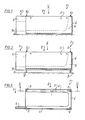
- Fig. 1 eine Seitenansicht eines erfindungsgemässen Sockelelementes in einer Tief läge,
- Fig. 2 eine Seitenansicht dieses Sockel elementes in einer Hochlage (stärker ausgefahrene Füsse),
- Fig. 3 eine Draufsicht nach Pfeil III in Fig. 1 und 2 auf das Sockelelement,
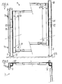
- Fig. 4 einen mehrfach gebrochenen, vergrösserten Schnitt nach Linie IV-IV in Fig. 3 des Metallgerüstes, wobei die linke Seite einen in Tiefstellung und die rechte Seite einen in Hochstellung befindlichen Fuss darstellend gezeichnet ist,
- Fig. 5 eine fragmentare Draufsicht auf das Metallgerüst,
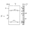
- Fig. 6 eine gegenüber den Fig. 1 und 2 vergrösserte Seitenansicht des Schildes, und
- Fig. 7 eine Ansicht des Schildes nach Pfeil VII in Fig. 6.
- 1 is a side view of a base element according to the invention in a low position,
- 2 is a side view of this base element in a high position (more extended feet),
- 3 shows a plan view according to arrow III in FIGS. 1 and 2 of the base element,
- 4 shows a multiply broken, enlarged section according to line IV-IV in FIG. 3 of the metal frame, the left side being drawn to show a foot in the down position and the right side being a foot in the up position,
- 5 is a fragmentary top view of the metal frame,
- Fig. 6 is an enlarged side view of the shield compared to Figs. 1 and 2, and
- 7 is a view of the shield according to arrow VII in Fig. 6th
Das in Fig. 1 bis 3 abgebildete Sockelelement 1 (für eine Badewanne) besteht aus einem Hauptteil 2, welcher den Abflussbereich 3 freilässt, sowie aus einem am Hauptteil 2 befestigten Schild 4, welcher den Abflussbereich 3 einseitig abdeckt.The base element 1 (for a bathtub) shown in FIGS. 1 to 3 consists of a main part 2, which leaves the drainage area 3 free, and a
Der Schild könnte für andere Zwecke auch eine zweiseitige oder gar dreiseitige Abdeckung des Abflussbereiches bewirken, was leicht einzusehen ist und daher nicht weiter dargestellt oder besprochen zu werden braucht. Bei den heute üblichen, relativ kleinen Badezimmern wird man eine Badewanne vorzugsweise in einer sie auf drei Seiten umgebenden Bauwerksnische unterbringen. Daher ist auch das hier abgebildete Sockelelement 1 auf einen solchen Fall abgestimmt.For other purposes, the sign could also cover the drainage area on two or even three sides, which is easy to see and therefore does not need to be shown or discussed further. In today's relatively small bathrooms, a bathtub will preferably be placed in a building niche surrounding it on three sides. Therefore, the
Der Hauptteil 2 weist innen eine einstückige Schaumstoffisolation 5, formgeschäumt genau auf das Wannenprofil auf, welche der Unterseite der einzusetzenden (nicht dargestellten) Badewanne nachgebildet ist (mit Ausnahme des Abflussbereiches). Diese Schaumstoffiso.lation 5 ist aussen mit Hartschaum-Mineralfaser Verbundplatten, durch in letztere eingedrungenen Schaumstoff fest verbunden, verkleidet. Diese Verkleidung kann vorzugsweise auch aus durchdringbaren Leichtbauplatten z.B. Holzwoll-Zementplatten gewöhnlichen Hartschaumplatten, mit oder ohne werkseitig aufgebrachten Grundputzauftrag bestehen, während es sich beim Schaumstoff um einen Polyurethanpressschaum mittlerer Härte handelt.The main part 2 has a one-
In der Schaumstoffisolation 5 eingebettet ist ein Metallgerüst 7 (Fig. 4 und 5), welches Füsse 8 umfasst, die in noch zu beschreibender Weise höhenverstellbar sind.Embedded in the
Ein Fuss 8 umfasst ein äusseres Führungsrohr 80 (Fig. 4 und 5), in welchem eine Gewindemutter 81 fest sitzt, in welcher der Gewindespindelteil 82 des Fusses 8 läuft, wobei durch das oben offene und vor dem Einlegen der Wanne mit einem Pilzpuffer abgedeckten Führungsrohr 80 der Fuss 8 mittels eines Schraubenziehers drehbar ist. Eine auf dem Boden B aufliegende Kunststoff-Reibschale 9 (Fig. 4) verhindert, dass die eingestellte Höhe sich ungewollt verändert. Die Reibschale 9 dient dabei als eine Drehsicherung.A
Es ist leicht einzusehen, dass auf diese Weise die Höhenlage und Neigung des Sockels und somit der später in ihn einzusetzenden Badewanne leicht von oben einstellbar ist.It is easy to see that in this way the height and inclination of the base and thus the bathtub to be inserted later can be easily adjusted from above.
Nach dieser Höheneinstellung kann man mittels Schrauben, welche man durch in Fig. 4 ersichtliche Löcher 10 in die Mauer (Dübel) dreht, sicher fixieren.After this height adjustment can be securely fixed by means of screws which are rotated into the wall (dowels) through
Der Schild 4 kann entweder jetzt schon oder erst nach dem Einsetzen der Badewanne montiert werden, wobei er mittels der an seinen beiden Endseiten 40 (Fig. 6 und 7) vorgesehenen Knopflöchern 41 (Fig. 7) an Schrauben 70 des Metallgerüstes 7 eingehängt und verschraubt werden kann. Eine Revisionsöffnung 42 (Fig. 6 und 7) im Schild 4 ist durch eine von Druckknopfverschlüssen 43 gehaltenen Deckel 44 verschliessbar bzw. zu öffnen. Auch hier ist eine Verbundplatte 60 (Fig. 7) als äussere Verkleidung vorgesehen. So ist eine optimale Anpassung des Sockels 1 an die baulichen Gegebenheiten erzielbar und durch die Montage- bzw. Revisionsöffnung 42 lässt sich der Abflussbereich 3 mit Isoliermaterial, z.B. Mineralfaserstopfwolle ausstopfen, was eine optimierte Isolation bringt, die aber von Fall zu Fall bei evtl. nötiger Revision der Wanneninstallation wieder entfernt und dann wieder neu gestopft werden kann.The
Die Funktion des Tragens und Isolierens erfüllt das Metallgerüst 7 mit seinen Füssen im Verein mit dem Isolierschaumstoff 5 und den Verbundplatten 6The metal frame 7 fulfills the function of supporting and insulating with its feet in combination with the insulating
Die Funktion der Schallisolation erfüllt der Isolierschaumstoff 5 im Verein mit den ihn rundum umgebenden Mineralfaser Verbundplatten, dem auf dem oberen Rand der Verbundplatten aufgeklebten Zellkautschukprofil sowie den schallbrückeverhindernden Pilzpuffer auf den Metallfussteilen und den Reibschalen.The insulating
Die Funktion des Schutzes und der Vliesenaufnahme erfüllen die auf der Aussenseite strukturierten Verbundplatten 6 und mit den Fussteilen 8 fest verbundene Eckenschutzprofile.The function of the protection and the fleece holder are performed by the composite panels 6 structured on the outside and firmly connected to the
Der Schild 4 vereinfacht dabei die Montage der Wanne und verschafft die Möglichkeit den Sockel in engster Passung in einer Gebäudenische unterzubringen.The
So ist trotz einer Aufgabenteilung ein synergistischer Effekt erzielbar.In this way, a synergistic effect can be achieved despite the division of tasks.
Der erfindungsgemässe Sockel lässt sich sehr einfach wirtschaftlich herstellen. Man legt in eine Stützform die mit den Metallbauteilen im voraus verbundenen Verbundplatten 6 ein. Als weitere Möglichkeit legt man in eine Stützform die Verbundplatten 6 ein und setzt aus Einzelstücken des Metallgerüst 7 zusammen, wobei man es leicht an den Verbundplatten 6 anheften und allenfalls seine Teile untereinander verkleben, vernieten, verschrauben, verschweissen oder sonst verbinden kann.The base according to the invention can be produced very simply and economically. The composite plates 6 connected in advance to the metal components are placed in a support mold. As a further possibility, the composite panels 6 are placed in a support mold and are composed of individual pieces of the metal frame 7, whereby one can easily attach them to the composite panels 6 and, if necessary, glue, rivet, screw, weld or otherwise connect their parts to one another.
Nun setzt man eine abzubildende Wanne darüber und schäumt darunter aus, wobei der Schaumstoff auch in die mineralfaserbewerten Verbundplatten eindringt und alles formschlüssig verbindet. Die mit einem Trennmittel vorbehandelte Wanne lässt sich entfernen. Der Schild 4 ist aus Metallbauteilen und Verbundplatten einfach herzustellen, wobei Verkleben zu den bevorzugten Verbindungsarten zählt.Now you place a tub to be imaged over it and foam under it, whereby the foam also penetrates the mineral fiber-rated composite panels and connects everything in a form-fitting manner. The tub, pre-treated with a release agent, can be removed. The
Claims (12)
Priority Applications (1)
| Application Number | Priority Date | Filing Date | Title |
|---|---|---|---|
| AT84810015T ATE22219T1 (en) | 1983-01-10 | 1984-01-09 | PREFABRICATED PLINTH ELEMENT FOR BATHTUBS AND SHOWER TRAYS. |
Applications Claiming Priority (2)
| Application Number | Priority Date | Filing Date | Title |
|---|---|---|---|
| CH107/83 | 1983-01-10 | ||
| CH107/83A CH658585A5 (en) | 1983-01-10 | 1983-01-10 | PRE-PREPARED BASE ELEMENT FOR BATH AND SHOWER TUBS. |
Publications (2)
| Publication Number | Publication Date |
|---|---|
| EP0116012A1 true EP0116012A1 (en) | 1984-08-15 |
| EP0116012B1 EP0116012B1 (en) | 1986-09-17 |
Family
ID=4179431
Family Applications (1)
| Application Number | Title | Priority Date | Filing Date |
|---|---|---|---|
| EP84810015A Expired EP0116012B1 (en) | 1983-01-10 | 1984-01-09 | Preformed base element for bath and shower tubs |
Country Status (4)
| Country | Link |
|---|---|
| EP (1) | EP0116012B1 (en) |
| AT (1) | ATE22219T1 (en) |
| CH (1) | CH658585A5 (en) |
| DE (2) | DE8306194U1 (en) |
Cited By (2)
| Publication number | Priority date | Publication date | Assignee | Title |
|---|---|---|---|---|
| EP0604899A1 (en) * | 1992-12-30 | 1994-07-06 | E. Missel GmbH & Co. | Support system for a bathtub |
| EP0635232A2 (en) * | 1993-07-19 | 1995-01-25 | E. Missel GmbH & Co. | Support system for bath tub or shower tray |
Citations (4)
| Publication number | Priority date | Publication date | Assignee | Title |
|---|---|---|---|---|
| DE1943650A1 (en) * | 1969-08-28 | 1971-04-01 | Heinrich Bunten | Bathtub support |
| DE2052979A1 (en) * | 1970-10-28 | 1972-05-31 | Auinger, Max, Braunau (Österreich) | Casing for built-in tubs or the like |
| FR2307637A1 (en) * | 1975-04-17 | 1976-11-12 | Cannes La Bocca Ind | Plastic sanitary installations with insulating foam filling - with shiny durable outer surfaces and high mechanical strength |
| DE3110120A1 (en) * | 1981-03-16 | 1982-09-23 | Leo 5342 Rheinbreitbach Menden | Plastic support for bathtubs and shower trays |
-
1983
- 1983-01-10 CH CH107/83A patent/CH658585A5/en not_active IP Right Cessation
- 1983-03-04 DE DE19838306194U patent/DE8306194U1/en not_active Expired
-
1984
- 1984-01-09 EP EP84810015A patent/EP0116012B1/en not_active Expired
- 1984-01-09 AT AT84810015T patent/ATE22219T1/en not_active IP Right Cessation
- 1984-01-09 DE DE8484810015T patent/DE3460713D1/en not_active Expired
Patent Citations (4)
| Publication number | Priority date | Publication date | Assignee | Title |
|---|---|---|---|---|
| DE1943650A1 (en) * | 1969-08-28 | 1971-04-01 | Heinrich Bunten | Bathtub support |
| DE2052979A1 (en) * | 1970-10-28 | 1972-05-31 | Auinger, Max, Braunau (Österreich) | Casing for built-in tubs or the like |
| FR2307637A1 (en) * | 1975-04-17 | 1976-11-12 | Cannes La Bocca Ind | Plastic sanitary installations with insulating foam filling - with shiny durable outer surfaces and high mechanical strength |
| DE3110120A1 (en) * | 1981-03-16 | 1982-09-23 | Leo 5342 Rheinbreitbach Menden | Plastic support for bathtubs and shower trays |
Cited By (3)
| Publication number | Priority date | Publication date | Assignee | Title |
|---|---|---|---|---|
| EP0604899A1 (en) * | 1992-12-30 | 1994-07-06 | E. Missel GmbH & Co. | Support system for a bathtub |
| EP0635232A2 (en) * | 1993-07-19 | 1995-01-25 | E. Missel GmbH & Co. | Support system for bath tub or shower tray |
| EP0635232A3 (en) * | 1993-07-19 | 1995-06-28 | Missel Gmbh & Co E | Support system for bath tub or shower tray. |
Also Published As
| Publication number | Publication date |
|---|---|
| CH658585A5 (en) | 1986-11-28 |
| DE8306194U1 (en) | 1983-11-10 |
| DE3460713D1 (en) | 1986-10-23 |
| EP0116012B1 (en) | 1986-09-17 |
| ATE22219T1 (en) | 1986-10-15 |
Similar Documents
| Publication | Publication Date | Title |
|---|---|---|
| EP2333174B1 (en) | Shower drainage system | |
| DE202011051140U1 (en) | Cover box for a shower drain system | |
| EP2245973A2 (en) | Base system for shower basins and shower trays | |
| EP1378197B1 (en) | Basement for a shower tray | |
| EP2060377A2 (en) | Bath structure and method for producing a bath structure | |
| DE3320617A1 (en) | Prefabricated casing for bathtubs | |
| EP0116012B1 (en) | Preformed base element for bath and shower tubs | |
| DE8507269U1 (en) | Device for supporting and covering sanitary basins, in particular bathtubs and shower trays | |
| EP0281957A1 (en) | Segment-shaped basin | |
| DE4100737C1 (en) | ||
| DE8018723U1 (en) | KIT FOR SANITARY CELLS | |
| CH701240A1 (en) | Shower tray base for use in shower room, has free spaces formed for accommodating fluid discharge pipe and surrounded by frame that is inserted into base opening, and sound insulation unit arranged at frame | |
| WO2000056200A1 (en) | Method for installing a tub support and tub shell mounted in a tub support | |
| EP0723757B1 (en) | Supporting system for bath tubs or shower tubs | |
| DE9402979U1 (en) | Sanitary cubicle | |
| EP0324443A1 (en) | Sanitary facility article and manufacturing process | |
| EP3339522B1 (en) | Shower channel installation kit or assembly | |
| DE19635759A1 (en) | Installation element for sanitary installations | |
| DE10159653B4 (en) | Window and door anchors | |
| DE3310084C1 (en) | Plastic carrier for bath and shower tubs | |
| EP1647644A2 (en) | Buidling module to be installed in a room of a building | |
| AT15994U1 (en) | WALL INSTALLATION UNIT | |
| AT382507B (en) | Device for supporting and cladding sanitary basins, in particular bathtubs and shower trays | |
| CH718686A2 (en) | Assembly device for use in creating a shower area and shower area with such a device. | |
| EP0293676B1 (en) | Segment-shaped basin |
Legal Events
| Date | Code | Title | Description |
|---|---|---|---|
| PUAI | Public reference made under article 153(3) epc to a published international application that has entered the european phase |
Free format text: ORIGINAL CODE: 0009012 |
|
| AK | Designated contracting states |
Designated state(s): AT BE DE FR GB IT LU NL SE |
|
| 17P | Request for examination filed |
Effective date: 19841214 |
|
| 17Q | First examination report despatched |
Effective date: 19860121 |
|
| GRAA | (expected) grant |
Free format text: ORIGINAL CODE: 0009210 |
|
| AK | Designated contracting states |
Kind code of ref document: B1 Designated state(s): AT BE DE FR GB IT LU NL SE |
|
| PG25 | Lapsed in a contracting state [announced via postgrant information from national office to epo] |
Ref country code: BE Effective date: 19860917 |
|
| REF | Corresponds to: |
Ref document number: 22219 Country of ref document: AT Date of ref document: 19861015 Kind code of ref document: T |
|
| PG25 | Lapsed in a contracting state [announced via postgrant information from national office to epo] |
Ref country code: SE Effective date: 19860930 |
|
| REF | Corresponds to: |
Ref document number: 3460713 Country of ref document: DE Date of ref document: 19861023 |
|
| ITF | It: translation for a ep patent filed | ||
| ET | Fr: translation filed | ||
| PG25 | Lapsed in a contracting state [announced via postgrant information from national office to epo] |
Ref country code: LU Free format text: LAPSE BECAUSE OF NON-PAYMENT OF DUE FEES Effective date: 19870131 |
|
| PLBE | No opposition filed within time limit |
Free format text: ORIGINAL CODE: 0009261 |
|
| STAA | Information on the status of an ep patent application or granted ep patent |
Free format text: STATUS: NO OPPOSITION FILED WITHIN TIME LIMIT |
|
| 26N | No opposition filed | ||
| GBPC | Gb: european patent ceased through non-payment of renewal fee | ||
| PG25 | Lapsed in a contracting state [announced via postgrant information from national office to epo] |
Ref country code: GB Free format text: LAPSE BECAUSE OF NON-PAYMENT OF DUE FEES Effective date: 19881122 |
|
| ITTA | It: last paid annual fee | ||
| PGFP | Annual fee paid to national office [announced via postgrant information from national office to epo] |
Ref country code: FR Payment date: 19971217 Year of fee payment: 15 |
|
| PGFP | Annual fee paid to national office [announced via postgrant information from national office to epo] |
Ref country code: NL Payment date: 19980130 Year of fee payment: 15 |
|
| PGFP | Annual fee paid to national office [announced via postgrant information from national office to epo] |
Ref country code: AT Payment date: 19990126 Year of fee payment: 16 |
|
| PG25 | Lapsed in a contracting state [announced via postgrant information from national office to epo] |
Ref country code: NL Free format text: LAPSE BECAUSE OF NON-PAYMENT OF DUE FEES Effective date: 19990801 |
|
| PG25 | Lapsed in a contracting state [announced via postgrant information from national office to epo] |
Ref country code: FR Free format text: LAPSE BECAUSE OF NON-PAYMENT OF DUE FEES Effective date: 19990930 |
|
| REG | Reference to a national code |
Ref country code: FR Ref legal event code: ST |
|
| PG25 | Lapsed in a contracting state [announced via postgrant information from national office to epo] |
Ref country code: AT Free format text: LAPSE BECAUSE OF NON-PAYMENT OF DUE FEES Effective date: 20000109 |
|
| PGFP | Annual fee paid to national office [announced via postgrant information from national office to epo] |
Ref country code: DE Payment date: 20020215 Year of fee payment: 19 |
|
| PG25 | Lapsed in a contracting state [announced via postgrant information from national office to epo] |
Ref country code: DE Free format text: LAPSE BECAUSE OF NON-PAYMENT OF DUE FEES Effective date: 20030801 |