EP0114945B1 - High temperature heat resistant structure - Google Patents
High temperature heat resistant structure Download PDFInfo
- Publication number
- EP0114945B1 EP0114945B1 EP83110703A EP83110703A EP0114945B1 EP 0114945 B1 EP0114945 B1 EP 0114945B1 EP 83110703 A EP83110703 A EP 83110703A EP 83110703 A EP83110703 A EP 83110703A EP 0114945 B1 EP0114945 B1 EP 0114945B1
- Authority
- EP
- European Patent Office
- Prior art keywords
- heat
- heat resistant
- resistant structure
- metal plate
- layer
- Prior art date
- Legal status (The legal status is an assumption and is not a legal conclusion. Google has not performed a legal analysis and makes no representation as to the accuracy of the status listed.)
- Expired
Links
Images
Classifications
-
- F—MECHANICAL ENGINEERING; LIGHTING; HEATING; WEAPONS; BLASTING
- F01—MACHINES OR ENGINES IN GENERAL; ENGINE PLANTS IN GENERAL; STEAM ENGINES
- F01D—NON-POSITIVE DISPLACEMENT MACHINES OR ENGINES, e.g. STEAM TURBINES
- F01D5/00—Blades; Blade-carrying members; Heating, heat-insulating, cooling or antivibration means on the blades or the members
- F01D5/12—Blades
- F01D5/14—Form or construction
- F01D5/18—Hollow blades, i.e. blades with cooling or heating channels or cavities; Heating, heat-insulating or cooling means on blades
- F01D5/187—Convection cooling
-
- F—MECHANICAL ENGINEERING; LIGHTING; HEATING; WEAPONS; BLASTING
- F01—MACHINES OR ENGINES IN GENERAL; ENGINE PLANTS IN GENERAL; STEAM ENGINES
- F01D—NON-POSITIVE DISPLACEMENT MACHINES OR ENGINES, e.g. STEAM TURBINES
- F01D25/00—Component parts, details, or accessories, not provided for in, or of interest apart from, other groups
- F01D25/08—Cooling; Heating; Heat-insulation
-
- F—MECHANICAL ENGINEERING; LIGHTING; HEATING; WEAPONS; BLASTING
- F01—MACHINES OR ENGINES IN GENERAL; ENGINE PLANTS IN GENERAL; STEAM ENGINES
- F01D—NON-POSITIVE DISPLACEMENT MACHINES OR ENGINES, e.g. STEAM TURBINES
- F01D5/00—Blades; Blade-carrying members; Heating, heat-insulating, cooling or antivibration means on the blades or the members
- F01D5/12—Blades
- F01D5/28—Selecting particular materials; Particular measures relating thereto; Measures against erosion or corrosion
- F01D5/284—Selection of ceramic materials
-
- F—MECHANICAL ENGINEERING; LIGHTING; HEATING; WEAPONS; BLASTING
- F05—INDEXING SCHEMES RELATING TO ENGINES OR PUMPS IN VARIOUS SUBCLASSES OF CLASSES F01-F04
- F05D—INDEXING SCHEME FOR ASPECTS RELATING TO NON-POSITIVE-DISPLACEMENT MACHINES OR ENGINES, GAS-TURBINES OR JET-PROPULSION PLANTS
- F05D2260/00—Function
- F05D2260/20—Heat transfer, e.g. cooling
- F05D2260/231—Preventing heat transfer
-
- Y—GENERAL TAGGING OF NEW TECHNOLOGICAL DEVELOPMENTS; GENERAL TAGGING OF CROSS-SECTIONAL TECHNOLOGIES SPANNING OVER SEVERAL SECTIONS OF THE IPC; TECHNICAL SUBJECTS COVERED BY FORMER USPC CROSS-REFERENCE ART COLLECTIONS [XRACs] AND DIGESTS
- Y10—TECHNICAL SUBJECTS COVERED BY FORMER USPC
- Y10T—TECHNICAL SUBJECTS COVERED BY FORMER US CLASSIFICATION
- Y10T428/00—Stock material or miscellaneous articles
- Y10T428/12—All metal or with adjacent metals
- Y10T428/12444—Embodying fibers interengaged or between layers [e.g., paper, etc.]
Definitions
- This invention relates to a heat resistant structure adapted to be used in a passage through which a high temperature fluid flows of the type comprising a heat resistant metal plate having a smooth outer surface exposed to the fluid, a layer of substance having a high heat transmission resistance extended along an internal surface of said metal plate, a heat conductive material provided in close contact with said layer on a side thereof away from said metal plate, and a cooling member for cooling said heat conductive material.
- a heat resistant structure heretofore used for providing structural walls or blades of a gas turbine has been constructed by use of a heat resistant metal plate I of a thickness t m , as shown in Fig. 1, one side surface l a of which is exposed to a high temperature fluid II of more than 1000°C, while the other side surface I b of which is exposed to a coolant III such as cooling water.
- the heat resistant structure of the above described construction suffers from following difficulties a and b when it is used in a gas turbine for providing above described members.
- the thermal stress ⁇ of the heat resistant metal plate I is proportional to the heat flux q flowing through the metal plate I and expressed as follows.
- C is a constant determined by the material of the metal plate I.
- the heat flux flowing through the metal plate I is on the other hand expressed as follows.
- T win represents a surface temperature on the low-temperature side of the heat resistant metal plate I
- T sat represents a saturation temperature of the coolant III (cooling water in this case).
- a degree of superheat ⁇ T sat is thus defined as follows. It is apparent that the coolant III tends to boil when the degree of superheat ⁇ T sat increases, and when the coolant boils, the advantage of providing a high heat conductivity a c on the low-temperature side of the metal plate I is lost, and the cooling effect of the coolant III is substantially reduced.
- the coolant III may be pressurized to increase the saturation temperature T sat and to reduce the degree of superheat ⁇ T sat .
- the coolant III since the coolant III must be pressurized at approximately 100 Kg/cm 2 for achieving the above described object, a material of a high strength must be utilized for the construction of the coolant passage. As a consequence, the thickness of the heat resistant metal plate I must be increased, thus restricting the increase of the saturation temperature.
- the boiling of the coolant may otherwise be prevented by reducing the surface temperature T win on the low-temperature side of the metal plate I.
- the surface temperature T win is expressed as wherein ⁇ m represents the heat conductivity of the metal plate I.
- ⁇ m represents the heat conductivity of the metal plate I.
- a heat resistant structure as mentioned at the beginning of this description, i.e. this document discloses a turbine blade. as a heat resistant structure generally comprising an outer protective cover, a heat insulation and a supporting material which are merely basic constructional members of the turbine blade. Furthermore it is provided passage in the hub of the rotor for passing a coolant as water therethrough. With this structure the turbine blades or the rotor may be thermally deformed.
- DE-A-1.476.730 there is disclosed a material structure for turbine-blades comprising a core of high heat conductivity, a layer of lower heat conductivity than the core, especially a layer of pure chromium, which can be applied on the core by electro-galvanization, and an additional outer coating on the chromium layer consisting of an intermetallic or ceramic material having a high oxidation resistance and having a low heat conductivity. According to the high temperatures there are created high thermal stresses between the several layers so that the materials usable are limited. Furthermore, the turbine blades may be deformed.
- the object of the present invention is to provide a heat resistant structure to be used in a flow passage or else of a high-temperature gas turbine, the structure providing a smooth surface on the high temperature side thereof, while the thermal stresses produced in the structure are substantially eliminated.
- said heat conductive material comprises a plurality of heat conductive bodies each spaced apart from adjacent bodies and each provided with a portion which is in slidable contact with a corresponding portion of the adjacent bodies; and said cooling member is a plurality of passages provided through each of said heat conductive bodies for passing a coolant therethrough, said heat resistant metal plate (1) is provided with a plurality of projections (2) on the internal surface thereof, and each of said heat conductive bodies is provided with a recess (5) engageable with the corresponding one of said projections with said high heat transmission resistance substance (3) being interposed between each projection and corresponding recess.
- the layer of a substance having a high heat transmission resistance may be a sheet of ceramic fibers or a layer of a ceramic coating.
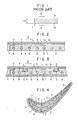
- a structure comprising a heat resistant metal plate 1 made of, for instance, a nickel-chromium alloy such as Inconel (Trade Name).
- the surface l a of the metal plate 1 is made smooth so as to assure a smooth flow of a high temperature fluid II.
- a ceramic fiber sheet 3 On an internal surface 1 b of the metal plate 1 is bonded a ceramic fiber sheet 3 exhibiting a high heat transmission resistance against the heat flow from the high temperature fluid II to the interior of the heat resistant structure through the metal plate 1.
- a plurality of heat conductive bodies 4 made of a heat conductive material such as copper and not constituting strength members are arranged along the internal surface of the metal plate 1.
- heat conductive bodies 4 are arranged to be slidable therebetween and along the internal surface of the ceramic fiber sheet 3, there is no possibility of creating thermal stresses in the heat conductive bodies 4.
- a plurality of coolant passages 6 are provided through each of the heat conductive bodies 4 for circulating a coolant 7 such as cooling water through the coolant passages 6.
- the heat conductive bodies 4 made of, for instance, copper and cooled by the coolant 7, are placed closely adjacent to the low-temperature side of the ceramic fiber sheet 3, and hence the temperature T" win of the heat conductive bodies 4 on the surface thereof contacting with the ceramic fiber sheet 3 is made substantially equal to, or slightly lower than the temperature T' win defined by equation (5).
- the degree of superheat ⁇ T' sat of the surface of the heat conductive bodies 4 is defined as and hence can be reduced to an extremely small value by reducing the surface temperature T' win of the ceramic fiber sheet 3.
- the reduction of the degree of superheat ATg a substantially eliminates the possibility of boiling of the coolant 7.
- the heat conductive bodies 4 are coupled with each other slidably, the difference between the thermal expansions of the heat resistant metal plate 1 and the heat conductive bodies 4 can be absorbed by the slidable engagement of the heat conductive bodies, and the creation of thermal stresses can be thereby prevented. For this reason, even in a case where the difference between the temperature Tg of the high temperature fluid II and the saturation temperature T c of the coolant is extremely large, most part of the temperature difference is supported by the ceramic fiber sheet 3 also not constituting . strength member, and thermal stresses in the heat resistant structure of this invention can be substantially eliminated. Furthermore, the boiling phenomenon of the coolant 7 can be eliminated regardless of the application of pressure to the coolant.
- Fig. 3 illustrates an embodiment of the present invention wherein a plurality of projections 2, each having a dovetail shaped cross-section, are provided along the inside surface l b of the metal plate 1 with a predetermined interval maintained therebetween.
- the ceramic fiber sheet 3 is extended along and bonded to the inside surface 1 b of the metal plate 1 so as to envelope the dovetail shaped projections 2.
- each of the heat conductive bodies 4 is provided with a recess 5 of a cross-sectional configuration capable of receiving the dovetail shaped projection 2 covered by the ceramic fiber sheet 3, so that the heat conductive bodies 4 are maintained at their positions with the ceramic fiber sheet 3 interposed between the metal plate 1 and the heat conductive bodies 4.
- the heat conductive bodies thus maintained at their positions are coupled with each other in a slidable manner for absorbing and eliminating the thermal stresses tending to be created in the heat conductive bodies 4.
- a plurality of coolant passages 6 are provided through each of the heat conductive bodies 4 as in the previous embodiment for passing a coolant 7 therethrough.
- a reinforcing plate 8 is further provided on the side of the heat conductive bodies away from the ceramic fiber sheet 3 for connecting the heat conductive bodies 4 on the side and reinforcing the structure on this side.
- Fig. 3 is also advantageous in that it has a smooth outer surface for allowing flow of the high temperature fluid II without any disturbance, thermal stresses tending to be created in the structure can be substantially eliminated, and the boiling phenomenon of the coolant can be avoided.
- Fig. 4 illustrates one preferred example utilizing the heat resistance structure such as shown in Fig. 3, wherein the heat resistant structure is applied to a turbine blade of a gas turbine.
- the construction of this example is substantially similar to that of the embodiment shown in Fig. 3, except that the heat resistant metal plate 1 is extended to envelope the entire construction of the turbine blade, and the reinforcing plate 8 of Fig. 3 is omitted.
- a plurality of projections 2 and mating recesses 5 of a dovetail shaped cross-section have been provided along the inside surface l b of the metal plate I and the opposing surfaces of the heat conductive bodies 4, the configuration of the projections 2 and the recesses 5 is not necessarily of the dovetail shape, and any other suitable configuration may otherwise be utilized.
- the ceramic fiber sheet 3 provided in the embodiments shown in Figs. 2, and 4 may be replaced by a layer of ceramic coating.
Landscapes
- Engineering & Computer Science (AREA)
- Mechanical Engineering (AREA)
- General Engineering & Computer Science (AREA)
- Chemical & Material Sciences (AREA)
- Ceramic Engineering (AREA)
- Materials Engineering (AREA)
- Turbine Rotor Nozzle Sealing (AREA)
- Laminated Bodies (AREA)
Applications Claiming Priority (2)
| Application Number | Priority Date | Filing Date | Title |
|---|---|---|---|
| JP57232318A JPS59120704A (ja) | 1982-12-27 | 1982-12-27 | 超高温耐熱壁体 |
| JP232318/82 | 1982-12-27 |
Publications (3)
| Publication Number | Publication Date |
|---|---|
| EP0114945A2 EP0114945A2 (en) | 1984-08-08 |
| EP0114945A3 EP0114945A3 (en) | 1984-08-22 |
| EP0114945B1 true EP0114945B1 (en) | 1988-05-18 |
Family
ID=16937318
Family Applications (1)
| Application Number | Title | Priority Date | Filing Date |
|---|---|---|---|
| EP83110703A Expired EP0114945B1 (en) | 1982-12-27 | 1983-10-26 | High temperature heat resistant structure |
Country Status (4)
| Country | Link |
|---|---|
| US (1) | US4573872A (enExample) |
| EP (1) | EP0114945B1 (enExample) |
| JP (1) | JPS59120704A (enExample) |
| DE (1) | DE3376664D1 (enExample) |
Families Citing this family (10)
| Publication number | Priority date | Publication date | Assignee | Title |
|---|---|---|---|---|
| US4790723A (en) * | 1987-01-12 | 1988-12-13 | Westinghouse Electric Corp. | Process for securing a turbine blade |
| US5348446A (en) * | 1993-04-28 | 1994-09-20 | General Electric Company | Bimetallic turbine airfoil |
| WO2003065948A1 (en) * | 2002-02-06 | 2003-08-14 | Koninklijke Philips Electronics N.V. | Personal care system with a personal care device and a cooling device |
| DE102004031255B4 (de) * | 2004-06-29 | 2014-02-13 | MTU Aero Engines AG | Einlaufbelag |
| US7247002B2 (en) * | 2004-12-02 | 2007-07-24 | Siemens Power Generation, Inc. | Lamellate CMC structure with interlock to metallic support structure |
| US8303247B2 (en) * | 2007-09-06 | 2012-11-06 | United Technologies Corporation | Blade outer air seal |
| US8241001B2 (en) * | 2008-09-04 | 2012-08-14 | Siemens Energy, Inc. | Stationary turbine component with laminated skin |
| US7828515B1 (en) * | 2009-05-19 | 2010-11-09 | Florida Turbine Technologies, Inc. | Multiple piece turbine airfoil |
| US9528382B2 (en) * | 2009-11-10 | 2016-12-27 | General Electric Company | Airfoil heat shield |
| US20110110772A1 (en) * | 2009-11-11 | 2011-05-12 | Arrell Douglas J | Turbine Engine Components with Near Surface Cooling Channels and Methods of Making the Same |
Citations (2)
| Publication number | Priority date | Publication date | Assignee | Title |
|---|---|---|---|---|
| DE1476730A1 (de) * | 1966-06-30 | 1970-03-26 | Winter Dr Heinrich | Kombinationswerkstoffe fuer Turbinenschaufeln |
| FR2030897A5 (enExample) * | 1969-11-21 | 1970-11-13 | Motoren Turbinen Union |
Family Cites Families (22)
| Publication number | Priority date | Publication date | Assignee | Title |
|---|---|---|---|---|
| US2157456A (en) * | 1935-02-23 | 1939-05-09 | Naamlooze Vennootshap Derde Nl | Method of uniting sprayed metal to wood |
| GB535566A (en) * | 1939-06-13 | 1941-04-11 | Oerlikon Maschf | Improvements in or relating to a thermal protective device for rotating heat engines |
| US2750147A (en) * | 1947-10-28 | 1956-06-12 | Power Jets Res & Dev Ltd | Blading for turbines and like machines |
| BE487558A (enExample) * | 1948-03-03 | |||
| GB722121A (en) * | 1952-04-16 | 1955-01-19 | Wiggin & Co Ltd Henry | Improvements relating to flame tubes of jet engines and to other metal articles |
| CH308578A (de) * | 1952-07-28 | 1955-07-31 | Bbc Brown Boveri & Cie | Gasturbinenbauteil aus Chromstahl mit einer keramischen Schutzschicht. |
| US3032316A (en) * | 1958-10-09 | 1962-05-01 | Bruce E Kramer | Jet turbine buckets and method of making the same |
| US3357850A (en) * | 1963-05-09 | 1967-12-12 | Gen Electric | Vibration damping turbomachinery blade |
| US3300180A (en) * | 1964-11-17 | 1967-01-24 | Worthington Corp | Segmented diaphragm assembly |
| GB1075910A (en) * | 1966-04-04 | 1967-07-19 | Rolls Royce | Improvements in or relating to blades for mounting in fluid flow ducts |
| US3619082A (en) * | 1968-07-05 | 1971-11-09 | Gen Motors Corp | Turbine blade |
| GB1284538A (en) * | 1968-11-19 | 1972-08-09 | Rolls Royce | Blade for a fluid flow machine |
| GB1291567A (en) * | 1968-12-16 | 1972-10-04 | Thomas Gordon Mcnish | Improvements in or relating to fibrous insulating materials |
| US3644060A (en) * | 1970-06-05 | 1972-02-22 | John K Bryan | Cooled airfoil |
| US3758233A (en) * | 1972-01-17 | 1973-09-11 | Gen Motors Corp | Vibration damping coatings |
| US4259037A (en) * | 1976-12-13 | 1981-03-31 | General Electric Company | Liquid cooled gas turbine buckets |
| DE2826184A1 (de) * | 1978-06-15 | 1979-12-20 | Daimler Benz Ag | Waermeisolation von gasturbinen- gehaeusen |
| US4273824A (en) * | 1979-05-11 | 1981-06-16 | United Technologies Corporation | Ceramic faced structures and methods for manufacture thereof |
| US4249291A (en) * | 1979-06-01 | 1981-02-10 | General Electric Company | Method for forming a liquid cooled airfoil for a gas turbine |
| JPS5645035A (en) * | 1979-09-19 | 1981-04-24 | Hitachi Ltd | Preparation of semiconductor-supporting electrode |
| DE3003347A1 (de) * | 1979-12-20 | 1981-06-25 | BBC AG Brown, Boveri & Cie., Baden, Aargau | Gekuehlte wand |
| US4370789A (en) * | 1981-03-20 | 1983-02-01 | Schilke Peter W | Fabrication of gas turbine water-cooled composite nozzle and bucket hardware employing plasma spray process |
-
1982
- 1982-12-27 JP JP57232318A patent/JPS59120704A/ja active Granted
-
1983
- 1983-10-26 DE DE8383110703T patent/DE3376664D1/de not_active Expired
- 1983-10-26 EP EP83110703A patent/EP0114945B1/en not_active Expired
- 1983-10-26 US US06/545,646 patent/US4573872A/en not_active Expired - Fee Related
Patent Citations (2)
| Publication number | Priority date | Publication date | Assignee | Title |
|---|---|---|---|---|
| DE1476730A1 (de) * | 1966-06-30 | 1970-03-26 | Winter Dr Heinrich | Kombinationswerkstoffe fuer Turbinenschaufeln |
| FR2030897A5 (enExample) * | 1969-11-21 | 1970-11-13 | Motoren Turbinen Union |
Also Published As
| Publication number | Publication date |
|---|---|
| EP0114945A2 (en) | 1984-08-08 |
| JPS59120704A (ja) | 1984-07-12 |
| DE3376664D1 (en) | 1988-06-23 |
| EP0114945A3 (en) | 1984-08-22 |
| JPH0375721B2 (enExample) | 1991-12-03 |
| US4573872A (en) | 1986-03-04 |
Similar Documents
| Publication | Publication Date | Title |
|---|---|---|
| EP0114945B1 (en) | High temperature heat resistant structure | |
| Silverstein et al. | The feasibility of heat pipe turbine vane cooling | |
| EP1521036B1 (en) | Seal assembly | |
| US3151712A (en) | Insulating structure | |
| US4540339A (en) | One-piece HPTR blade squealer tip | |
| US5626211A (en) | Multi-layer disk brake rotor | |
| GB2051255A (en) | Method for forming a liquid cooled airfoil for a gas turbine | |
| US5564496A (en) | Composite parting sheet | |
| GB2066113A (en) | Methods of making turbine nozzles having coolant flow tubes | |
| WO1996032618A1 (en) | Carbon/carbon composite parallel plate heat exchanger and method of fabrication | |
| US3242984A (en) | Heat exchangers with reinforced fins | |
| EP3176533B1 (en) | Cross flow ceramic heat exchanger and method for manufacturing | |
| JPH02105095A (ja) | 防熱遮蔽体 | |
| GB2040598A (en) | Rotor of superconductive generator | |
| US4981761A (en) | Ceramic and metal bonded composite | |
| JPH076366B2 (ja) | ガスタ−ビン静翼 | |
| US6171053B1 (en) | Device for thermally insulating a steam turbine casing | |
| US3010398A (en) | Composite nose cone structure | |
| Wells | ORNL Fusion Power Demonstration Study: Lithium as a Blanket Coolant. | |
| JPS6050329B2 (ja) | 超電導コイル装置 | |
| WO2000031485A1 (en) | Counter-flow heat exchanger with integral manifolds and passage | |
| Vasudevan et al. | Thermal bending of a tri-metal strip | |
| JP3024408B2 (ja) | 真空装置用加熱ユニット | |
| Picologlou et al. | Lithium-cooled blankets for advanced tokamaks | |
| Schramm et al. | Analysis of Coolant-flow Requirements for an Improved, Internal-strut-supported, Air-cooled Turbine-rotor Blade |
Legal Events
| Date | Code | Title | Description |
|---|---|---|---|
| PUAI | Public reference made under article 153(3) epc to a published international application that has entered the european phase |
Free format text: ORIGINAL CODE: 0009012 |
|
| PUAL | Search report despatched |
Free format text: ORIGINAL CODE: 0009013 |
|
| 17P | Request for examination filed |
Effective date: 19831124 |
|
| AK | Designated contracting states |
Designated state(s): CH DE FR GB LI |
|
| AK | Designated contracting states |
Designated state(s): CH DE FR GB LI |
|
| GRAA | (expected) grant |
Free format text: ORIGINAL CODE: 0009210 |
|
| AK | Designated contracting states |
Kind code of ref document: B1 Designated state(s): CH DE FR GB LI |
|
| REF | Corresponds to: |
Ref document number: 3376664 Country of ref document: DE Date of ref document: 19880623 |
|
| ET | Fr: translation filed | ||
| PLBE | No opposition filed within time limit |
Free format text: ORIGINAL CODE: 0009261 |
|
| STAA | Information on the status of an ep patent application or granted ep patent |
Free format text: STATUS: NO OPPOSITION FILED WITHIN TIME LIMIT |
|
| 26N | No opposition filed | ||
| PGFP | Annual fee paid to national office [announced via postgrant information from national office to epo] |
Ref country code: GB Payment date: 19961017 Year of fee payment: 14 |
|
| PGFP | Annual fee paid to national office [announced via postgrant information from national office to epo] |
Ref country code: DE Payment date: 19961104 Year of fee payment: 14 Ref country code: CH Payment date: 19961104 Year of fee payment: 14 |
|
| PG25 | Lapsed in a contracting state [announced via postgrant information from national office to epo] |
Ref country code: GB Free format text: LAPSE BECAUSE OF NON-PAYMENT OF DUE FEES Effective date: 19971026 |
|
| PG25 | Lapsed in a contracting state [announced via postgrant information from national office to epo] |
Ref country code: LI Free format text: LAPSE BECAUSE OF NON-PAYMENT OF DUE FEES Effective date: 19971031 Ref country code: CH Free format text: LAPSE BECAUSE OF NON-PAYMENT OF DUE FEES Effective date: 19971031 |
|
| REG | Reference to a national code |
Ref country code: CH Ref legal event code: PL |
|
| GBPC | Gb: european patent ceased through non-payment of renewal fee |
Effective date: 19971026 |
|
| PG25 | Lapsed in a contracting state [announced via postgrant information from national office to epo] |
Ref country code: DE Free format text: LAPSE BECAUSE OF NON-PAYMENT OF DUE FEES Effective date: 19980801 |
|
| PGFP | Annual fee paid to national office [announced via postgrant information from national office to epo] |
Ref country code: FR Payment date: 19981009 Year of fee payment: 16 |
|
| PG25 | Lapsed in a contracting state [announced via postgrant information from national office to epo] |
Ref country code: FR Free format text: LAPSE BECAUSE OF NON-PAYMENT OF DUE FEES Effective date: 20000630 |
|
| REG | Reference to a national code |
Ref country code: FR Ref legal event code: ST |