EP0114913B1 - Bellows connection for vehicle bodies - Google Patents
Bellows connection for vehicle bodies Download PDFInfo
- Publication number
- EP0114913B1 EP0114913B1 EP19830100826 EP83100826A EP0114913B1 EP 0114913 B1 EP0114913 B1 EP 0114913B1 EP 19830100826 EP19830100826 EP 19830100826 EP 83100826 A EP83100826 A EP 83100826A EP 0114913 B1 EP0114913 B1 EP 0114913B1
- Authority
- EP
- European Patent Office
- Prior art keywords
- cable
- tensioning
- boot
- boot according
- toggle
- Prior art date
- Legal status (The legal status is an assumption and is not a legal conclusion. Google has not performed a legal analysis and makes no representation as to the accuracy of the status listed.)
- Expired
Links
Images


Classifications
-
- B—PERFORMING OPERATIONS; TRANSPORTING
- B60—VEHICLES IN GENERAL
- B60D—VEHICLE CONNECTIONS
- B60D5/00—Gangways for coupled vehicles, e.g. of concertina type
- B60D5/003—Bellows for interconnecting vehicle parts
-
- B—PERFORMING OPERATIONS; TRANSPORTING
- B61—RAILWAYS
- B61D—BODY DETAILS OR KINDS OF RAILWAY VEHICLES
- B61D17/00—Construction details of vehicle bodies
- B61D17/04—Construction details of vehicle bodies with bodies of metal; with composite, e.g. metal and wood body structures
- B61D17/20—Communication passages between coaches; Adaptation of coach ends therefor
- B61D17/22—Communication passages between coaches; Adaptation of coach ends therefor flexible, e.g. bellows
-
- B—PERFORMING OPERATIONS; TRANSPORTING
- B62—LAND VEHICLES FOR TRAVELLING OTHERWISE THAN ON RAILS
- B62D—MOTOR VEHICLES; TRAILERS
- B62D47/00—Motor vehicles or trailers predominantly for carrying passengers
- B62D47/02—Motor vehicles or trailers predominantly for carrying passengers for large numbers of passengers, e.g. omnibus
- B62D47/025—Motor vehicles or trailers predominantly for carrying passengers for large numbers of passengers, e.g. omnibus articulated buses with interconnecting passageway, e.g. bellows
-
- F—MECHANICAL ENGINEERING; LIGHTING; HEATING; WEAPONS; BLASTING
- F16—ENGINEERING ELEMENTS AND UNITS; GENERAL MEASURES FOR PRODUCING AND MAINTAINING EFFECTIVE FUNCTIONING OF MACHINES OR INSTALLATIONS; THERMAL INSULATION IN GENERAL
- F16G—BELTS, CABLES, OR ROPES, PREDOMINANTLY USED FOR DRIVING PURPOSES; CHAINS; FITTINGS PREDOMINANTLY USED THEREFOR
- F16G11/00—Means for fastening cables or ropes to one another or to other objects; Caps or sleeves for fixing on cables or ropes
- F16G11/12—Connections or attachments, e.g. turnbuckles, adapted for straining of cables, ropes, or wire
Definitions
- the invention relates to a bellows according to the preamble of claim 1.
- Such bellows are used between the mutually facing ends of two articulated vehicle members to enclose a 'transition gate between these two vehicle members in a tunnel shape, so that people are protected from the wind, bad weather and dust can switch from one to the other vehicle link via the "transition bridge".
- the invention is concerned with the attachment of such a bellows on the two facing end faces of the two vehicle members.
- the vehicle wall is channel-shaped and a sealing profile is inserted into this channel running in the circumferential direction of the bellows.
- a tensioning cable is sewn into the associated bellows.
- the tensioning cable lies in the gutter of the vehicle wall and holds the bellows against the vehicle wall.
- either the tensioning cable must be elastic in itself or the distance between the ends of the essentially inextensible tensioning cable must be changeable.
- a tension cable that is essentially inextensible, the two ends of which are connected to each other in the area of the lower, horizontal bellows wall by a turnbuckle. If the turnbuckle is closed, the bellows end is fixed in the gutter of the respective vehicle link. Is the turnbuckle opened, the bellows can be removed from the trough-shaped end of the vehicle wall, so that it is separated from the vehicle member.
- the turnbuckle consists of two threaded pins, the pin ends of which are turned towards one another and can be screwed into a coupling piece to different degrees and the other ends of which act as a holder for the respective tension cable ends are formed.
- the object of the invention is to design a bellows of the type mentioned at the outset in such a way that it is much easier to use without significant additional construction work compared to the known solutions and without impairing the functionality.
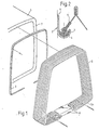
- a peripheral frame 2 is permanently assigned to the rear, open end of a front vehicle member 1, for example by being screwed onto the end face 3 of the vehicle member 1 (FIG. 1).
- the frame 2 is trough-shaped, i.e. it has the cross-section of a U with legs of different lengths (FIG. 2), the longer leg 4 being used to screw the frame onto the end face of the vehicle member.
- a tension cable 7 is sewn at its end, which lies in the channel-shaped bed of the frame 2.
- a rubber profile 6 is inserted into the frame bed and secured there, and the tensioning cable 7 is supported in the frame bed (with the bellows wall engaged) via this rubber profile.
- the tensioning cable 7 is tensioned in the end cloth of the bellows in order to prevent the bellows end from inadvertently reaching the shorter leg of the U of the frame 2.
- this voltage is generated or eliminated as follows. It is assumed that the bellows is configured identically at its two ends and is assigned to one end face of the two successive vehicle members with each of its ends.
- the two ends of the tensioning cable 7 are connected to one another in the region of the lower, horizontal bellows wall 5a with a toggle lever tensioner 8.
- the toggle lever clamp 8 is built on a base plate 9 which is held on two bearing blocks 10 (FIG. 3).
- Each bearing block 10 is provided with a bearing pin 12 pointing in the longitudinal direction of the vehicle, on which a lever 13 is pivotably mounted at one end.
- the other end of each lever 13 is designed as a manually operated handle 13a.
- a coupling rod 14 is articulated on a pin 15 of the lever 13, the longitudinal axis of which extends parallel to the longitudinal axis of the bearing pin 12.
- the coupling rod 14 has at its end facing away from the articulation a threaded section onto which two nuts 16, 17 are screwed at an axial distance. Between the two nuts 16, 17 there is a U-shaped coupling piece 18 with one leg, the nut 16 closer to the articulation of the coupling rod 14 on the lever 13 directly on the outside of the Leg of the coupling piece rests, while a spring element in the form of a plate spring 19 is located between the inside of this leg and the nut 17 lying further away from the articulation. On the other leg of the coupling piece, the tension cable 7 is attached at one end, for which purpose a clamping sleeve 20 is used.
- the ends of the tensioning cable are almost the smallest possible distance apart, so that the bellows is fixed relative to the end of the vehicle.
- the levers 13 are folded onto the base plate 9 with their handles 13a.
- the distance of the pin 15 from the base plate 9 is slightly less than the distance of the bearing pin 12.
- the levers 13 are pivoted about the bearing pin 12 in the direction of the arrows 21, the springs 19 being additionally tensioned until the pins 12, 15 and the spring 19 lie in a plane parallel to the base plate 9 in order to relax when the lever 13 is pivoted further, the distance between the ends of the tensioning cable 7 increasing and the bellows end being able to be lifted above the end frame.
- the device is thus easy to use, it is simple in construction and reliable.
- the operation is simple because only the levers 13 can be moved in one of two directions and a large change in the distance between the tension cable ends is possible by means of the two levers. Due to the possibility of changing the distance between the two tension cable ends, the bellows end can be reliably fixed in a relatively deep groove of the lead frame. Operational safety also benefits from the fact that when the lever is pivoted between its end positions, the point must be swiveled through in which the spring is maximally tensioned.
- the bias of the spring 19 can be changed, thereby changing the tension with which the respective tensioning cable is held in the groove of the bellows end.
- the effective basic length of the tensioning cable can be changed, it being advisable to make such changes to the two parts which are preferably to be provided. distribute the tensioning device evenly.
- the plane in which the tensioning levers 13 are to be pivoted in accordance with the arrows 21 is a plane parallel to the lower, horizontal bellows wall 5a, the tensioning levers 13 lying below the eyes 10, so that these are gripped by the bellows from one side and below them the tension levers are pivotable.
- a disk 3a is pivotally mounted about the longitudinal axis of the pin 2a by means of a vertical pin 2a.
- pins 4a and 5b two oppositely directed circular toggle levers 6a and 7a are articulated on the disk 3a.
- the toggle levers 6a, 7a are each articulated in a pin 100 or 200 to a clamping bolt 8a, 9a.
- the clamping bolts are adjustable in the direction of their longitudinal axes and for this purpose are each mounted in a bearing block 10a or 11a of the base plate 9.
- axially adjustable cable brackets 12c and 13c are mounted axially adjustable through longitudinal slots.
- the tensioning rope for tensioning and fixing the bellows at the vehicle end is fastened with its two ends, for which purpose these have saddle-shaped depressions in which the tensioning cable ends are suspended with lead-shaped receptacles.
- the articulation points 5b, 200 on the one hand and 4a, 100 on the other hand are on different sides of the pin 2a, the distance between the articulation points 100 and 200 and thus the ends of the rope is small, the rope is tensioned and pulls the end of it assigned bellows in a groove of the associated vehicle, on which the bellows is fixed in this way.
- the disk 3a is pivoted out of this operating position shown, so that the articulation points 4a, 100 on the one hand and 5b, 200 on the other hand are so laterally offset that the distance between the articulation points 100, 200 and thus the Rope ends is larger and the rope can be lifted out of the gutter of the vehicle and the bellows can be separated from the vehicle.
- the articulation points 100, 200 lie on a line which is axially aligned with the longitudinal axes of the clamping bolts 8a, 9a, while the articulation points 4a, 5b lie laterally from this line and when the disk is pivoted into the other position through this line be moved with which one .
- Ubertot Vietnamese Kunststoffhaloseun 9 for secure determination of the operating position shown given is.
- the pivotal movement of the disk 3a is a multi-surface pin 22 connected to it, on which a manually operated key can be attached.
- compression springs for example plate springs 12b, 13b, are inserted between each of the two cable brackets 12c, 13c and the lock nuts 12a, 13a associated therewith in order to be able to change the contact pressure of the tensioning cable to a limited extent in order to prevent the cable bracket from being inadvertently lifted off the lock nuts and in order to maintain a relative degree of freedom when tightening the lock nuts and in order to be able to compensate for different shrink widths of the vehicle, bellows and tensioning cable, especially at extreme temperatures.
Landscapes
- Engineering & Computer Science (AREA)
- Mechanical Engineering (AREA)
- General Engineering & Computer Science (AREA)
- Chemical & Material Sciences (AREA)
- Combustion & Propulsion (AREA)
- Transportation (AREA)
- Life Sciences & Earth Sciences (AREA)
- Wood Science & Technology (AREA)
- Flexible Shafts (AREA)
- Diaphragms And Bellows (AREA)
Description
Die Erfindung bezieht sich auf einen Faltenbalg gemäß dem Gattungsbegriff des Anspruches 1. Solche Faltenbälge werden zwischen den einander zugekehrten Enden zweier gelenkig miteinander verbundener Fahrzeugglieder eingesetzt, um eine 'Ubergangsbrucke zwischen diesen beiden Fahrzeuggliedern tunnelförmig zu umschließen, damit Personen vom Fahrtwind, Witterungsunbilden und Staub geschützt über die "Ubergangsbrücke vom einen zum anderen Fahrzeugglied überwechseln können.The invention relates to a bellows according to the preamble of claim 1. Such bellows are used between the mutually facing ends of two articulated vehicle members to enclose a 'transition gate between these two vehicle members in a tunnel shape, so that people are protected from the wind, bad weather and dust can switch from one to the other vehicle link via the "transition bridge".
Im einzelnen befaßt sich die Erfindung mit der Befestigung eines solchen Faltenbalges an den beiden einander zugekehrten Stirnseiten der beiden Fahrzeugglieder. Für diese Befestigung ist die Fahrzeugwand rinnenförmig ausgebildet und in diese in Umfangsrichtung des Balges verlaufende Rinne ist ein Dichtprofil eingelegt. In das zugehörige Balgende ist ein Spannkabel eingenäht. Das Spannkabel legt sich in die Rinne der Fahrzeugwand und hält den Faltenbalg gegenüber der Fahrzeugwand. Um das Balgende dem Fahrzeuggliedende zuordnen oder vom Fahrzeuggliedende trennen zu können, muß entweder das Spannkabel in sich elastisch sein oder der Abstand zwischen den Enden des im wesentlichen undehnbaren Spannkabels muß veränderbar sein. "Üblich ist dabei ein in sich im wesentlichen nicht dehnbares Spannkabel, dessen beide Enden im Bereich der unteren, horizontalen Balgwand durch ein Spannschloß miteinander verbunden sind. Ist das Spannschloß geschlossen, so ist das Faltenbalgende in der Rinne des jeweiligen Fahrzeuggliedes festgelegt. Ist das Spannschloß geöffnet, so kann der Faltenbalg aus dem rinnenförmigen Ende der Fahrzeugwand herausgenommen werden, so daß er von dem Fahrzeugglied getrennt ist. Das Spannschloß besteht aus zwei Gewindezapfen, deren einander zugehrten Zapfenenden unterschiedlich weit in ein Kupplungsstück einzudrehen sind und deren andere Enden als Halterung für das jeweilige Spannkabelende ausgebildet sind.In particular, the invention is concerned with the attachment of such a bellows on the two facing end faces of the two vehicle members. For this fastening, the vehicle wall is channel-shaped and a sealing profile is inserted into this channel running in the circumferential direction of the bellows. A tensioning cable is sewn into the associated bellows. The tensioning cable lies in the gutter of the vehicle wall and holds the bellows against the vehicle wall. In order to assign the bellows end to the vehicle link end or to be able to separate it from the vehicle link end, either the tensioning cable must be elastic in itself or the distance between the ends of the essentially inextensible tensioning cable must be changeable. "It is usual to have a tension cable that is essentially inextensible, the two ends of which are connected to each other in the area of the lower, horizontal bellows wall by a turnbuckle. If the turnbuckle is closed, the bellows end is fixed in the gutter of the respective vehicle link. Is the turnbuckle opened, the bellows can be removed from the trough-shaped end of the vehicle wall, so that it is separated from the vehicle member.The turnbuckle consists of two threaded pins, the pin ends of which are turned towards one another and can be screwed into a coupling piece to different degrees and the other ends of which act as a holder for the respective tension cable ends are formed.
Diese Vorrichtung arbeitet technisch einwandfrei, der bauliche Aufwand ist vertretbar, der notwendige Betätigungsaufwand wird dagegen häufig als zu groß empfunden. Trotz des zu hoch empfundenen Betätigungsaufwandes wurden bisher andere Lösungen noch nicht angeboten.This device works technically flawlessly, the constructional effort is justifiable, but the necessary operating effort is often perceived as too great. Despite the excessive effort involved in operating the system, other solutions have not yet been offered.
Aufgabe der Erfindung ist es, einen Faltenbalg der eingangs genannten Gattung so auszubilden, daß er ohne wesentlichen baulichen Mehraufwand gegenuber den bekannten Lösungen und ohne Beeinträchtigung der Funktionsfähigkeit wesentlich einfacher zu bedienen ist.The object of the invention is to design a bellows of the type mentioned at the outset in such a way that it is much easier to use without significant additional construction work compared to the known solutions and without impairing the functionality.
Der Lösung der Aufgabe dienen die Merkmale des Patentanspruchs 1.The features of claim 1 serve to solve the problem.
Die Erfindung wird nachfolgend anhand der Zeichnung näher erläutert. In der Zeichnung zeigen:
- Fig.1 eine Gesamtanordnung eines Faltenbalges,
- Fig.2 eine Schnittdarstellung einer Einzelheit,
- Fig.3 die erfindungsgemäße Spannvorrichtung, im
Figurenteil 3a im wesentlichen die rechts, im Figurenteil 3b im wesentlichen die links von der Mittellinie M-M liegenden Teile der Spannvorrichtung, - Fig.4 eine weitere Ausführungsform der Erfindung als Gesamtanordnung und in Seitenansicht und
- Fig.5 die Anordnung der Fig.4 in der Draufsicht.
- 1 shows an overall arrangement of a bellows,
- 2 shows a sectional illustration of a detail,
- 3 shows the tensioning device according to the invention, in FIG. 3a essentially the parts of the tensioning device lying on the right, in FIG. 3b essentially the parts on the left of the center line MM,
- 4 shows a further embodiment of the invention as an overall arrangement and in side view and
- 5 shows the arrangement of Figure 4 in plan view.
Dem hinteren, offenen Ende eines vorderen Fahrzeuggliedes 1 ist fest ein umlaufender Rahmen 2 zugeordnet, indem er beispielsweise auf die Stirnseite 3 des Fahrzeuggliedes 1 aufgeschraubt ist (Fig.1). Der Rahmen 2 ist rinnenförmig, d.h. er hat den Querschnitt eines U mit ungleich langen Schenkeln (Fig.2), wobei der längere Schenkel 4 dem Anschrauben des Rahmens an der Stirnseite des Fahrzeuggliedes dient. In den Faltenbalg 5 ist an seinem Ende ein Spannkabel 7 eingenäht, welches sich in das rinnenförmige Bett des Rahmens 2 legt. Zur besseren Dichtung ist in das Rahmenbett ein Gummiprofil 6 eingelegt und dort gesichert, und über dieses Gummiprofil stützt sich das Spannkabel 7 (unter Einschaltung der Balgwand) im Rahmenbett ab. Um das Faltenbalgende in dem Rahmen 2 zu halten, liegt das Spannkabel 7 mit Spannung in dem Endtuch des Faltenbalges, um das Faltenbalgende daran zu hindern, ungewollt über den kürzeren Schenkel des U des Rahmens 2 zu gelangen. Diese Spannung wird erfindungsgemäß wie folgt erzeugt bzw. beseitigt. Es ist dabei davon ausgegangen, daß der Faltenbalg an seinen beiden Enden gleich ausgestaltet ist, und mit jedem seiner Enden einer Stirnseite der beiden aufeinanderfolgenden Fahrzeugglieder zugeordnet ist.A
Die beiden Enden des Spannkabels 7 sind im Bereich der unteren, horizontalen Balgwand 5a mit einem Kniehebelspanner 8 miteinander verbunden. Der Kniehebelspanner 8 ist auf einer Grundplatte 9 aufgebaut, die an zwei Lagerböcken 10 gehalten ist (Fig.3). Jeder Lagerbock 10 ist mit einem in Fahrzeuglängsrichtung weisenden Lagerzapfen 12 versehen, auf dem ein Hebel 13 mit seinem einen Ende schwenkbar gelagert ist. Das andere Ende jedes Hebels 13 ist als manuell zu betätigender Griff 13a ausgebildet. Zwischen beiden Enden des Hebels 13 ist eine Kupplungsstange 14 an einem Zapfen 15 des Hebels 13 angelenkt, dessen Längsachse zur Längsachse des Lagerzapfens 12 parallel verläuft. Die Kupplungsstange 14 weist an ihrem der Anlenkung abgekehrten Ende einen Gewindeabschnitt auf, auf den in axialem Abstand zwei Muttern 16, 17 aufgeschraubt sind. Zwischen den beiden Muttern 16, 17 befindet sich ein U-förmiges Kupplungsstück 18 mit seinem einen Schenkel, wobei die der Anlenkung der Kupplungsstange 14 an dem Hebel 13 nähere Mutter 16 direkt an der Außenseite des Schenkels des Kupplungsstückes anliegt, während sich zwischen der Innenseite dieses Schenkels und der der Anlenkung entfernter liegenden Mutter 17 ein Federelement in der Form einer Tellerfeder 19 befindet. Am anderen Schenkel des Kupplungsstückes ist das Spannkabel 7 mit seinem einen Ende angehängt, wozu eine Klemmhülse 20 dient.The two ends of the
In der dargestellten Betriebsstellung der Vorrichtung haben die Enden des Spannkabels nahezu den geringstmöglichen Abstand voneinander, so daß der Faltenbalg gegenüber dem Fahrzeugende festgelegt ist. Die Hebel 13 sind mit ihren Griffen 13a an die Grundplatte 9 angeklappt. Der Abstand des Zapfens 15 von der Grundplatte 9 ist etwas geringer als der Abstand des Lagerzapfens 12. Zum Ausbau des Faltenbalges werden die Hebel 13 um den Lagerzapfen 12 in Richtung der Pfeile 21 geschwenkt, wobei zunächst die Federn 19 zusätzlich gespannt werden, bis die Zapfen 12, 15 und die Feder 19 in einer zur Grundplatte 9 parallelen Ebene liegen, um sich beim weiteren Schwenken der Hebel 13 zu entspannen, wobei sich der Abstand zwischen den Enden des Spannkabels 7 vergrößert und das Faltenbalgende über den Endrahmen gehoben werden kann.In the illustrated operating position of the device, the ends of the tensioning cable are almost the smallest possible distance apart, so that the bellows is fixed relative to the end of the vehicle. The
Die Vorrichtung ist damit einfach zu bedienen, sie ist einfach im Aufbau und betriebssicher. Die Bedienung ist einfach, weil nur die Hebel 13 in einer von zwei Richtungen zu bewegen sind und mittels der beiden Hebel eine große Änderung des Abstandes zwischen den Spannkabelenden möglich ist. Durch die Änderungsmöglichkeit für den Abstand zwischen beiden Spannkabelenden kann das Faltenbalgende in einer relativ tiefen Rinne des Anschlußrahmens und damit zuverlässig festgelegt werden. Der Betriebssicherheit kommt auch zugute, daß beim Schwenken der Hebel zwischen ihren Endstellungen der Punkt durchschwenkt werden muß, in dem die Feder maximal gespannt ist.The device is thus easy to use, it is simple in construction and reliable. The operation is simple because only the
Durch Verstellen der Muttern 16, 17 relativ zueinander kann die Vorspannung der Feder 19 verändert werden, womit die Spannung verändert wird, mit der das jeweilige Spannkabel in der Rinne des Balgendes gehalten ist. Durch Verstellen der Muttern 16,17 in gleicher Weise gegenüber dem Gewindezapfen 14 kann die effektive Grundlänge des Spannkabels verändert werden, wobei es zweckmäßig ist, derartige Veränderungen auf die vorzugweise vorzusehenden beiden Teile. der Spannvorrichtung gleichmäßig zu verteilen.By adjusting the
Die Ebene, in der die Spannhebel 13 entsprechend den Pfeilen 21 zu schwenken sind, ist eine zur unteren, horizontalen Balgwand 5a parallele Ebene, wobei die Spannhebel 13 unterhalb der Augen 10 liegen, so daß diese von der einen Seite her vom Faltenbalg erfaßt werden und unter ihnen die Spannhebel schwenkbar sind.The plane in which the
Der nachfolgend anhand der Fig.3 und 4 beschriebenen weiteren Ausgestaltung der vorliegenden Erfindung liegt die Aufgabe zugrunde, die Bedienung der Spannvorrichtung noch weiter zu vereinfachen.The further embodiment of the present invention described below with reference to FIGS. 3 and 4 is based on the task of further simplifying the operation of the tensioning device.
Während bei der vorbeschriebenen Lösung die Einzelbetätigung jedes der beiden Kniehebel vorgesehen ist, sieht die nachfolgend beschriebene Ausgestaltung vor, daß die beiden Kniehebel mittels eines gemeinsamen Betätigungselementes gleichzeitig zu betätigen sind.While the above-described solution provides for the individual actuation of each of the two toggle levers, the configuration described below provides that the two toggle levers can be actuated simultaneously by means of a common actuating element.
Es ist hier durch eine Betätigung des Kniehebelspanners mit seinen beiden Kniehebeln durch einen einzigen Handgriff möglich, der Faltenbalg kann an jedem Ende mit einem einzigen Handgriff gespannt und entspannt werden.It is possible here by actuating the toggle lever tensioner with its two toggle levers by means of a single handle; the bellows can be tensioned and relaxed at each end with a single handle.
Auf der Grundplatte 9 ist mittels eines vertikalen Zapfens 2a eine Scheibe 3a um die Längsachse des Zapfens 2a verschwenkbar gelagert. Mit Zapfen 4a und 5b sind an der Scheibe 3a zwei entgegengesetzt gerichtete kreisbogenförmige Kniehebel 6a und 7a angelenkt. An ihren äußeren Enden sind die Kniehebel 6a, 7a in je einem Zapfen 100 bzw. 200 an je einem Spannbolzen 8a, 9a angelenkt. Die Spannbolzen sind in Richtung ihrer Längsachsen verstellbar und hierzu in je einem Lagerbock 10a bzw. 11 a der Grundplatte 9 gelagert. Am äußeren Ende der Spannbolzen ist axial einstellbar je ein durch Längsschlitze radial federnder Seilbock 12c bzw. 13c gelagert. An den beiden Seilböcken ist das Spannseil zum Spannen und Festlegen des Faltenbalges am Fahrzeugende mit seinen beiden Enden befestigt, wozu diese sattelförmige Vertiefungen aufweisen, in denen die Spannkabelenden mit plombenförmigen Aufnahmen eingehängt sind. In der dargestellten Stellung der Scheibe liegen die Gelenkpunkte 5b, 200 einerseits und 4a, 100 andererseits auf verschiedenen Seiten des Zapfens 2a, der Abstand zwischen den Gelenkpunkten 100 und 200 und damit den Seilenden ist gering, das Seil ist gespannt und zieht das Ende des ihm zugeordneten Faltenbalges in eine Rinne des zugehörigen Fahrzeuges, an dem auf diese Weise der Faltenbalg festgelegt ist. Zum Öffnen der Verriegelung und zu entsprechenden Längen des Spannseiles wird die Scheibe 3a aus dieser dargestellten Betriebsstellung herausgeschwenkt, so daß die Gelenkpunkte 4a, 100 einerseits und 5b, 200 andererseits so seitlich versetzt werden, daß der Abstand zwischen den Gelenkpunkten 100, 200 und damit den Seilenden größer ist und das Seil aus der Rinne des Fahrzeuges herausgehoben werden kann und der Faltenbalg vom Fahrzeug getrennt werden kann.On the
In der dargestellten Betriebsstellung liegen die Gelenkpunkte 100, 200 auf einer Linie, die achsgleich zu den Längsachsen der Spannbolzen 8a, 9a liegen, während die Gelenkpunkte 4a,5b seitlich von dieser Linie liegen und beim Schwenken der Scheibe in die andere Stellung durch diese Linie hindurch bewegt werden, womit eine .Ubertotpunktsteuerun9 zur sicheren Festlegung der dargestellten Betriebsstellung gegeben ist.In the operating position shown, the articulation points 100, 200 lie on a line which is axially aligned with the longitudinal axes of the clamping bolts 8a, 9a, while the
Der Schwenkung der Scheibe 3a dient ein mit ihr verbundener mehrflächiger Zapfen 22, auf dem ein manuell zu betätigender Schlüssel aufgesteckt werden kann.The pivotal movement of the
Zweckmäßigerweise werden zwischen jedem der beiden Seilböcke 12c, 13c und der ihnen zugehörigen Kontermutter 12a, 13a Druckfedern, beispielsweise Tellerfedern 12b, 13b eingelegt, um den Anpreßdruck des Spannkabels in Grenzen verändern zu können, um ein unbeabsichtigtes Abheben des Seilbockes von den Kontermuttern zu verhindern und um einen relativen Freiheitsgrad beim Anziehen der Kontermuttern zu erhalten und um insbesondere bei extremen Temperaturen unterschiedliche Schrumpfweiten von Fahrzeug, Balg und Spannkabel ausgleichen zu können.Expediently, compression springs, for example plate springs 12b, 13b, are inserted between each of the two
Claims (11)
Priority Applications (2)
| Application Number | Priority Date | Filing Date | Title |
|---|---|---|---|
| DE8383100826T DE3367352D1 (en) | 1983-01-28 | 1983-01-28 | Bellows connection for vehicle bodies |
| EP19830100826 EP0114913B1 (en) | 1983-01-28 | 1983-01-28 | Bellows connection for vehicle bodies |
Applications Claiming Priority (1)
| Application Number | Priority Date | Filing Date | Title |
|---|---|---|---|
| EP19830100826 EP0114913B1 (en) | 1983-01-28 | 1983-01-28 | Bellows connection for vehicle bodies |
Publications (2)
| Publication Number | Publication Date |
|---|---|
| EP0114913A1 EP0114913A1 (en) | 1984-08-08 |
| EP0114913B1 true EP0114913B1 (en) | 1986-11-05 |
Family
ID=8190270
Family Applications (1)
| Application Number | Title | Priority Date | Filing Date |
|---|---|---|---|
| EP19830100826 Expired EP0114913B1 (en) | 1983-01-28 | 1983-01-28 | Bellows connection for vehicle bodies |
Country Status (2)
| Country | Link |
|---|---|
| EP (1) | EP0114913B1 (en) |
| DE (1) | DE3367352D1 (en) |
Families Citing this family (7)
| Publication number | Priority date | Publication date | Assignee | Title |
|---|---|---|---|---|
| DE8802944U1 (en) * | 1988-03-04 | 1988-08-04 | Hübner Gummi- und Kunststoff GmbH, 3500 Kassel | Clamping device |
| FR2629034B1 (en) * | 1988-03-25 | 1990-04-20 | Caoutchouc Manuf Plastique | DEFORMABLE MEMBRANE FOR INTERCIRCULATION TUNNEL BETWEEN SUCCESSIVE RAILWAY OR ROAD VEHICLES |
| FR2645097B1 (en) * | 1989-03-28 | 1991-06-21 | Caoutchouc Manuf Plastique | DEFORMABLE MEMBRANE FOR INTERCIRCULATION TUNNEL BETWEEN SUCCESSIVE RAILWAY OR ROAD VEHICLES WITH GROWING DEPTH WAVE |
| DE4105449A1 (en) * | 1991-02-21 | 1992-08-27 | Huebner Gummi & Kunststoff | BELLOWS FOR TRANSITIONS FROM ARTICULATED VEHICLES, HOLDING PROFILE FOR THE FASTENING OF SUCH A BELLOWS ON A ARTICULATED VEHICLE AND KIT FROM SUCH A BELLOWS AND SUCH A HOLDING PROFILE AND INSTALLATION |
| DE4330042A1 (en) * | 1993-09-06 | 1995-03-09 | Huebner Gummi & Kunststoff | Bellows insertable between two articulated vehicle links |
| AT8054U1 (en) | 2005-03-15 | 2006-01-15 | Ultimate Transp Equipment Gmbh | BELLOW - VEHICLE MOUNTING |
| CN110254455B (en) * | 2019-07-02 | 2020-10-13 | 中车长春轨道客车股份有限公司 | Rail vehicle and windshield hanging device thereof |
Family Cites Families (5)
| Publication number | Priority date | Publication date | Assignee | Title |
|---|---|---|---|---|
| BE421312A (en) * | 1936-04-29 | |||
| FR1313154A (en) * | 1961-11-08 | 1962-12-28 | Tension clip and quick lock | |
| CH485535A (en) * | 1968-01-19 | 1970-02-15 | Huebner Kg Kurt | Bellows connection on vehicles composed of several sections |
| GB1228200A (en) * | 1968-11-14 | 1971-04-15 | ||
| DE2726724A1 (en) * | 1976-06-24 | 1978-01-05 | Max Frei | Fencing wire stretching and connecting clamp - has polygonal bolt passed through clamp disc with holes to anchor wire ends and L-shaped locking element |
-
1983
- 1983-01-28 EP EP19830100826 patent/EP0114913B1/en not_active Expired
- 1983-01-28 DE DE8383100826T patent/DE3367352D1/en not_active Expired
Also Published As
| Publication number | Publication date |
|---|---|
| EP0114913A1 (en) | 1984-08-08 |
| DE3367352D1 (en) | 1986-12-11 |
Similar Documents
| Publication | Publication Date | Title |
|---|---|---|
| EP0623490B1 (en) | Roof rack for motor vehicles with roof rails | |
| CH668232A5 (en) | CARRYING DEVICE FOR A LOAD. | |
| DE29501244U1 (en) | Jig | |
| EP0114913B1 (en) | Bellows connection for vehicle bodies | |
| DE69002308T2 (en) | AXLE LIFTING DEVICE FOR A VEHICLE WITH A PNEUMATIC SUSPENSION SYSTEM. | |
| DE3036580A1 (en) | JOINT FITTING FOR SEATS WITH ADJUSTABLE BACKREST, IN PARTICULAR MOTOR VEHICLE SEATS | |
| DE202012006839U1 (en) | Fixing clamp for solar modules | |
| DE3139697A1 (en) | BELLOWS FOR VEHICLES | |
| EP0396890A1 (en) | Device for cleaning conveyor belts | |
| DE19934384A1 (en) | Bicycle carrier for mounting on motor vehicle roof has fasteners for wheels and frame mounted on relatively moveable continuously adjustable clamp parts | |
| DE3211940C2 (en) | Adjustment bracket for the plate of a drawing table | |
| DE4112923A1 (en) | Clamping device for fixing glass panels - has right-angled support web on one clamping jaw | |
| DE20317350U1 (en) | Axle lifter for utility vehicles, especially trailers, has counter bearings formed by hinge bolt and shock absorber support bolt | |
| EP0644072B1 (en) | Bellows for installation between two articulatingly coupled vehicle units | |
| DE4237018C1 (en) | Lid for the inspection opening of a centrifuge | |
| EP2995502B1 (en) | Roof rack assembly for a motor vehicle | |
| DD202274A5 (en) | RAIL CLAMP | |
| EP0221255A2 (en) | Vehicle rear view mirror | |
| DE2126347C3 (en) | Device for cleaning the wheels of vehicles | |
| CH641521A5 (en) | Setting-out device for windows or doors | |
| DE69711624T2 (en) | CARRIER | |
| DE3605929C2 (en) | ||
| EP0776020B1 (en) | Safety switch device | |
| AT394164B (en) | Load-carrying device | |
| EP0262094A1 (en) | Discharge door for fluid bulk material |
Legal Events
| Date | Code | Title | Description |
|---|---|---|---|
| PUAI | Public reference made under article 153(3) epc to a published international application that has entered the european phase |
Free format text: ORIGINAL CODE: 0009012 |
|
| AK | Designated contracting states |
Designated state(s): BE CH DE FR LI |
|
| 17P | Request for examination filed |
Effective date: 19850205 |
|
| GRAA | (expected) grant |
Free format text: ORIGINAL CODE: 0009210 |
|
| AK | Designated contracting states |
Kind code of ref document: B1 Designated state(s): BE CH DE FR LI |
|
| ET | Fr: translation filed | ||
| REF | Corresponds to: |
Ref document number: 3367352 Country of ref document: DE Date of ref document: 19861211 |
|
| PLBE | No opposition filed within time limit |
Free format text: ORIGINAL CODE: 0009261 |
|
| STAA | Information on the status of an ep patent application or granted ep patent |
Free format text: STATUS: NO OPPOSITION FILED WITHIN TIME LIMIT |
|
| 26N | No opposition filed | ||
| PGFP | Annual fee paid to national office [announced via postgrant information from national office to epo] |
Ref country code: CH Payment date: 19971209 Year of fee payment: 16 |
|
| PGFP | Annual fee paid to national office [announced via postgrant information from national office to epo] |
Ref country code: BE Payment date: 19971212 Year of fee payment: 16 |
|
| PGFP | Annual fee paid to national office [announced via postgrant information from national office to epo] |
Ref country code: FR Payment date: 19980128 Year of fee payment: 16 |
|
| PGFP | Annual fee paid to national office [announced via postgrant information from national office to epo] |
Ref country code: DE Payment date: 19980129 Year of fee payment: 16 |
|
| PG25 | Lapsed in a contracting state [announced via postgrant information from national office to epo] |
Ref country code: LI Free format text: LAPSE BECAUSE OF NON-PAYMENT OF DUE FEES Effective date: 19990131 Ref country code: CH Free format text: LAPSE BECAUSE OF NON-PAYMENT OF DUE FEES Effective date: 19990131 Ref country code: BE Free format text: LAPSE BECAUSE OF NON-PAYMENT OF DUE FEES Effective date: 19990131 |
|
| BERE | Be: lapsed |
Owner name: HUBNER GUMMI- UND KUNSTSTOFF G.M.B.H. Effective date: 19990131 |
|
| REG | Reference to a national code |
Ref country code: CH Ref legal event code: PL |
|
| PG25 | Lapsed in a contracting state [announced via postgrant information from national office to epo] |
Ref country code: FR Free format text: LAPSE BECAUSE OF NON-PAYMENT OF DUE FEES Effective date: 19990930 |
|
| PG25 | Lapsed in a contracting state [announced via postgrant information from national office to epo] |
Ref country code: DE Free format text: LAPSE BECAUSE OF NON-PAYMENT OF DUE FEES Effective date: 19991103 |
|
| REG | Reference to a national code |
Ref country code: FR Ref legal event code: ST |