EP0114772B1 - Blank for making a package provided with a handle, and corresponding preformed package and package - Google Patents
Blank for making a package provided with a handle, and corresponding preformed package and package Download PDFInfo
- Publication number
- EP0114772B1 EP0114772B1 EP19840400109 EP84400109A EP0114772B1 EP 0114772 B1 EP0114772 B1 EP 0114772B1 EP 19840400109 EP19840400109 EP 19840400109 EP 84400109 A EP84400109 A EP 84400109A EP 0114772 B1 EP0114772 B1 EP 0114772B1
- Authority
- EP
- European Patent Office
- Prior art keywords
- root
- tongue portion
- bend line
- side panels
- blank
- Prior art date
- Legal status (The legal status is an assumption and is not a legal conclusion. Google has not performed a legal analysis and makes no representation as to the accuracy of the status listed.)
- Expired
Links
- 238000004026 adhesive bonding Methods 0.000 claims description 7
- 239000000463 material Substances 0.000 claims description 7
- 230000003014 reinforcing effect Effects 0.000 claims description 5
- 238000005452 bending Methods 0.000 claims description 4
- 210000002105 tongue Anatomy 0.000 description 40
- 238000004806 packaging method and process Methods 0.000 description 24
- 230000002787 reinforcement Effects 0.000 description 5
- 238000002513 implantation Methods 0.000 description 3
- 241001415961 Gaviidae Species 0.000 description 2
- 238000009434 installation Methods 0.000 description 2
- 238000005304 joining Methods 0.000 description 2
- 241001080024 Telles Species 0.000 description 1
- 230000015572 biosynthetic process Effects 0.000 description 1
- 235000019504 cigarettes Nutrition 0.000 description 1
- 238000005520 cutting process Methods 0.000 description 1
- 239000003599 detergent Substances 0.000 description 1
- 230000018109 developmental process Effects 0.000 description 1
- 230000000694 effects Effects 0.000 description 1
- 230000012447 hatching Effects 0.000 description 1
- 238000004519 manufacturing process Methods 0.000 description 1
Images

Classifications
-
- B—PERFORMING OPERATIONS; TRANSPORTING
- B65—CONVEYING; PACKING; STORING; HANDLING THIN OR FILAMENTARY MATERIAL
- B65D—CONTAINERS FOR STORAGE OR TRANSPORT OF ARTICLES OR MATERIALS, e.g. BAGS, BARRELS, BOTTLES, BOXES, CANS, CARTONS, CRATES, DRUMS, JARS, TANKS, HOPPERS, FORWARDING CONTAINERS; ACCESSORIES, CLOSURES, OR FITTINGS THEREFOR; PACKAGING ELEMENTS; PACKAGES
- B65D5/00—Rigid or semi-rigid containers of polygonal cross-section, e.g. boxes, cartons or trays, formed by folding or erecting one or more blanks made of paper
- B65D5/42—Details of containers or of foldable or erectable container blanks
- B65D5/44—Integral, inserted or attached portions forming internal or external fittings
- B65D5/46—Handles
- B65D5/46008—Handles formed separately from the container body
- B65D5/46016—Straps used as handles fixed to the container by glueing, stapling, heat-sealing
-
- B—PERFORMING OPERATIONS; TRANSPORTING
- B65—CONVEYING; PACKING; STORING; HANDLING THIN OR FILAMENTARY MATERIAL
- B65D—CONTAINERS FOR STORAGE OR TRANSPORT OF ARTICLES OR MATERIALS, e.g. BAGS, BARRELS, BOTTLES, BOXES, CANS, CARTONS, CRATES, DRUMS, JARS, TANKS, HOPPERS, FORWARDING CONTAINERS; ACCESSORIES, CLOSURES, OR FITTINGS THEREFOR; PACKAGING ELEMENTS; PACKAGES
- B65D5/00—Rigid or semi-rigid containers of polygonal cross-section, e.g. boxes, cartons or trays, formed by folding or erecting one or more blanks made of paper
- B65D5/42—Details of containers or of foldable or erectable container blanks
- B65D5/44—Integral, inserted or attached portions forming internal or external fittings
- B65D5/46—Handles
- B65D5/46008—Handles formed separately from the container body
-
- B—PERFORMING OPERATIONS; TRANSPORTING
- B65—CONVEYING; PACKING; STORING; HANDLING THIN OR FILAMENTARY MATERIAL
- B65D—CONTAINERS FOR STORAGE OR TRANSPORT OF ARTICLES OR MATERIALS, e.g. BAGS, BARRELS, BOTTLES, BOXES, CANS, CARTONS, CRATES, DRUMS, JARS, TANKS, HOPPERS, FORWARDING CONTAINERS; ACCESSORIES, CLOSURES, OR FITTINGS THEREFOR; PACKAGING ELEMENTS; PACKAGES
- B65D5/00—Rigid or semi-rigid containers of polygonal cross-section, e.g. boxes, cartons or trays, formed by folding or erecting one or more blanks made of paper
- B65D5/42—Details of containers or of foldable or erectable container blanks
- B65D5/54—Lines of weakness to facilitate opening of container or dividing it into separate parts by cutting or tearing
- B65D5/5405—Lines of weakness to facilitate opening of container or dividing it into separate parts by cutting or tearing for opening containers formed by erecting a blank in tubular form
- B65D5/542—Lines of weakness to facilitate opening of container or dividing it into separate parts by cutting or tearing for opening containers formed by erecting a blank in tubular form the lines of weakness being provided in the container body
- B65D5/5425—Lines of weakness to facilitate opening of container or dividing it into separate parts by cutting or tearing for opening containers formed by erecting a blank in tubular form the lines of weakness being provided in the container body and defining after rupture a lid hinged to the upper edge of the container body
Definitions
- the present invention relates generally to packages made from a cardboard blank, corrugated cardboard, or other sheet material suitably cut and grooved, comprising in one piece, for the constitution of a body, a plurality of side panels successively articulated two by two by parallel fold lines, and, for the constitution of a cover, flaps each individually extending said side panels, beyond root fold lines perpendicular to the previous fold lines .
- said flaps are at least partially superimposed two by two, being suitably secured to each other, for example by gluing.
- a detachable strip precut for this purpose in continuity in at least some, successive, side panels, parallel to the fold lines roots of the flaps which extend these, near the said fold lines roots , usually allows to decapitate the whole, on at least three sides.
- the part thus detached from the body of the packaging at the opening of the latter can, at the option of the user, ensure the reclosing thereof, in particular if the entire contents of a such packaging is not consumed all at once, as is the case for example for detergents sold using relatively large capacity packaging.
- the present invention generally relates to an arrangement making it possible to overcome this difficulty very simply and economically.
- a blank of cardboard, corrugated cardboard or other sheet material of the type described in the aforementioned document US-A-2836343 said blank comprising, in one piece, for the constitution of a package, a plurality of side panels successively articulated two by two by parallel fold lines, hereinafter called for simple convenience the main fold lines, and, beyond the root fold lines perpendicular to said lines main folding, flaps each individually extending at least some of said side panels, with, precut in at least some successive, side panels, parallel to the fold lines roots of the flaps extending these, a detachable strip, this blank being characterized in that, in each of two flaps extending two opposite side panels is cut a tongue, which itself comes from a line of root folding perpendicular to the lines of main folding, and the length of which, measured perpendicularly from a bend line su- perposableà to the root fold line of the corresponding flap or coincident therewith, is known per E- higher than that at which is established,
- Such a detachable portion of said tongue is in practice intended to form the reinforcement to be attached to a side panel when it must be secured thereto, by one of its ends, a handle.
- such reinforcement advantageously does not require, for its implementation, any particular manipulation, which facilitates, and makes more economical, the installation of such a handle.
- the tongue according to the invention coming from the very surface of a flap usually used anyway, advantageously does not entail any additional consumption of material, and therefore no additional cost.
- the present invention also relates to the packaging produced using such a blank, as well as the packaging blank, advantageously available flat, previously obtained by bending the tubular sheath thereof.
- a blank 10 according to the invention is of the type comprising, in one piece, for the constitution of a package to which a handle must be attached independently. 11, a plurality of side panels 12 successively articulated two by two by parallel fold lines 13, said below for the sake of convenience, main fold lines.
- the desired packaging having to have in cross section a quadrangular contour, four side panels 12 are provided, namely two side panels of smaller width 12A, and two side panels of larger width 12B, which alternate with the previous ones.
- each of these side panels 12A, 12B is generally quadrangular.
- At least some of the side panels 12 extend, each individually, beyond the root fold lines 15 perpendicular to the main fold lines 13, by flaps 18.
- a detachable strip 27, delimited by precut lines 28, is precut in continuity in at least some, successive, side panels 12, parallel to the root fold lines 16 of the flaps 18 extending these, near said root fold lines 16.
- such a detachable strip 27 affects three successive side panels 12, namely the two narrower side panels 12A, and the wider panel 12B framed by them; it also affects the joining strip 15.
- a tongue 20 is cut out itself from a root fold line 21 perpendicular to the main fold lines 13, and whose length L i , measured perpendicularly from a stackable fold line at the root fold line 16 of the corresponding flap 18A or merged with it, is greater than that L 2 at which is established, relative to said root fold line 16, that of the precut lines 28 of the detachable strip 27 which is closest to said root fold line 16.
- the root fold line 21 of a tongue 20 is distinct from the root fold line 16 of the flap 18A in which this tongue 20 is cut, it extends substantially parallel thereto, and, at a distance D1 from it substantially equal to that D2 separating it from said root fold line 16, said tongue 20 is assigned a fold line 24, which is substantially parallel to the previous two, but whose folding direction is opposite to that of the latter.
- This fold line 24 can therefore be superimposed on the root fold line 16 of the corresponding flap 18A, and it is from this, in this embodiment, that the length L, specified above, of the relevant portion of a tongue 20.
- such a fold line 24 is embodied by a buttonhole cut 25 in its central region, to facilitate the corresponding folding.
- the tongue 20 thus cut from a flap 18A extends along one of the sides of the latter, said side being that closest to the flap 18B framed by the flaps 18A in which such a tongue 20 is cut.
- the tongues 20 of the flaps 18A are established symmetrically on either side of the flap 18B framed by these flaps 18A, as close as possible to this flap 18B.
- a detachable portion 23 implanted so as to be able to be superposed on the panel side 12 considered when, as it will appear below, said tongue 20 is folded over it by folding around its root fold line 21.
- the detachable portion 23 of a tongue 20 forms a lateral extension of the latter, so as to be located substantially at right of the median axis of the side panel 12A corresponding.
- the detachable portion 23 of a tongue 20 according to the invention is substantially square relative to the current part thereof, at the end of this tongue 20 furthest from its root fold line 21, and the precut line 22 which delimits it is substantially oblique with respect to said root fold line 21.
- the detachable portion 23 thus presented by a tongue 20 according to the invention is generally situated at a distance L ' 1 from the folding pin 24 of this tongue 20 at least equal to the distance L' z to which is established, relative to the root fold line 16 concerned, that of the precut lines 28 of the detachable strip 27 which is the farthest from said root fold line 16.
- a reinforcing strip 29 is continuously superimposed on the detachable strip 27, in the central region thereof.
- this detachable strip 27 extends over all of the side panels 12, perpendicular to the main fold lines 13.
- the side panels 12 can also each be individually extended, beyond the root fold lines perpendicular to the main fold lines 13, by clean flaps to jointly form a base for the desired packaging.
- flaps may for example be flaps of the type described above, but without a tab according to the invention.
- it may be flaps specific to the constitution of an automatic background.
- an independent background can be provided.
- the blank 10 according to the invention can easily be made of cardboard, corrugated cardboard, or other sheet material suitably cut and grooved, its crease lines constituting the lines of folding, and also the precut lines when, from place to place, they are sufficiently accentuated to cross it right through.
- detachable portions 23 of the tongues 20 are, first of all, detachable portions 23 of the tongues 20 according to the invention.
- the tongues 20 are folded over the side panels 12A, by folding 180 ° around their root fold line 21, FIG. 2A.
- the root fold lines 21 of the tongues 20 are superimposed on the root fold lines 16 of the corresponding flaps 18A, and, taking into account the relative values of the lengths L 1 , L 2 , L ' 1 , L' 2 specified above, the detachable portions 23 of the tongues 20 are superimposed on the side panels 12A, on the internal face of the latter, below the detachable strip 27, in the median zone of said side panels 12A.
- the extreme side panel 12B is then folded down, by folding it 180 ° around the main fold line 13 which connects it to the adjacent side panel 12A, then, after bonding of the fastening strip 15 , at folding of the extreme side panel 12A, by folding it 180 ° around the main fold line 13 which connects it to the adjacent side panel 12B, FIG. 2B.
- the two end side panels 12A, 12B thereof are secured to one another, by the fastening strip 15 provided for this effect.
- the tubular packaging blank 32 thus obtained is, in a manner known per se, advantageously deliverable flat.
- the packaging 34 advantageously has, in advance, a local reinforcement on the internal face of each of its two opposite side panels 12A on which such implantation must take place.
- the fitting of the handle 11 can for example be done using rivets 35, one for each of its ends to allow it to be swiveled around of these.
- the flap 18B extending the side panel 12B end which is the one to the right of one of the main fold lines 13 which is the notch 30 locally interrupting the reinforcing strip 29, is folded last, and forms therefore the top of the package 34.
- the detachable strip 27 is removed, which leads to decapitating the body 36 of this packaging on three sides.
- flap 18B which forms the top thereof, with, joined by bonding thereto, the other flaps 18, the assembly constituting a cover 37 with the parts of the side panels 12.
- the tongues 20 then form, by their remaining part, projecting from the flap 18B concerned or, in other words, from the cover 37 in the constitution of which the latter participates, lugs 39 which, each disposed respectively laterally along the edges of such a cover 37, in the corner areas of the latter opposite the hinge by which it is articulated to the body 36, are able to engage in this body 36, in contact with the corresponding side panels 12A, and thus allow the body 36 to be closed, FIG. 8.
- no local reinforcement of the side panels 12A is provided for the implantation of a handle, either that such local reinforcement is provided otherwise, or that another type of handle be adopted.
- the tongues 20 according to the invention therefore do not have a detachable portion.
- the root fold line of such a tongue 20 is coincident with the root fold line 16 of the flap 18A in which it is cut, and this is therefore counted from this fold line. root 16 that the length L is measured, to be taken into consideration.
- the tongues 20 according to the invention extend in the middle part of the flaps 18A concerned.
- the application of the invention is not limited to only packages whose cross section is quadrangular, but can also be envisaged for example for packages whose cross section is hexagonal.
Landscapes
- Engineering & Computer Science (AREA)
- Mechanical Engineering (AREA)
- Cartons (AREA)
Description
La présente invention concerne d'une manière générale les emballages réalisés à partir d'un flan en carton, carton ondulé, ou autre matériau en feuille convenablement découpé et rainé, comportant d'un seul tenant, pour la constitution d'un corps, une pluralité de panneaux de côté successivement articulés deux à deux par des lignes de pliage parallèles, et, pourla constitution d'un couvercle, des rabats prolongeant chacun individuellement lesdits panneaux de côté, au-delà de lignes de pliage racines perpendiculaires aux lignes de pliage précédentes.The present invention relates generally to packages made from a cardboard blank, corrugated cardboard, or other sheet material suitably cut and grooved, comprising in one piece, for the constitution of a body, a plurality of side panels successively articulated two by two by parallel fold lines, and, for the constitution of a cover, flaps each individually extending said side panels, beyond root fold lines perpendicular to the previous fold lines .
Après remplissage d'un tel emballage, lesdits rabats sont au moins partiellement superposés deux à deux, en étant convenablement solidarisés les uns aux autres, par exemple par collage.After filling such a package, said flaps are at least partially superimposed two by two, being suitably secured to each other, for example by gluing.
Pour accès ultérieur à son contenu, une bande détachable, prédécoupée à cet effet en continuité dans certains au moins, successifs, des panneaux de côté, parallèlement aux lignes de pliage racines des rabats qui prolongent ceux-ci, à proximité desdites lignes de pliage racines, permet usuellement de décapiter l'ensemble, sur au moins trois côtés.For subsequent access to its content, a detachable strip, precut for this purpose in continuity in at least some, successive, side panels, parallel to the fold lines roots of the flaps which extend these, near the said fold lines roots , usually allows to decapitate the whole, on at least three sides.
Il est connu, notamment par le brevet U.S-A-2836343 concernant le domaine des petits emballages, notamment les paquets de cigarettes, de réaliser une bande détachable propre à permettre de décapiter certains desdits panneaux de côté permettant la constitution d'un couvercle par la partie ainsi détachée de ceux-ci, ledit couvercle demeurant alors articulé au corps de l'emballage correspondant.It is known, in particular from US-A-2836343 relating to the field of small packages, in particular cigarette packs, to produce a detachable strip capable of decapitating some of said side panels allowing the constitution of a cover by part thus detached from them, said cover then remaining articulated to the body of the corresponding packaging.
Avec un tel emballage, il est souhaitable que la partie ainsi détachée du corps de l'emballage à l'ouverture de celui-ci puisse, au gré de l'utilisateur, en assurer la refermeture, notamment si la totalité du contenu d'un tel emballage n'est pas consommé en une seule fois, comme c'est le cas par exemple pour les détergents commercialisés à l'aide d'emballages de relativement grande capacité.With such a packaging, it is desirable that the part thus detached from the body of the packaging at the opening of the latter can, at the option of the user, ensure the reclosing thereof, in particular if the entire contents of a such packaging is not consumed all at once, as is the case for example for detergents sold using relatively large capacity packaging.
Le plus souvent, dans les emballages dits pour cette raison en deux parties, il est associé à cet effet au corps d'un tel emballage un fourreau interne qui, dépassant en hauteur celui-ci, forme avec lui une feuillure permettant l'emboîtement du couvercle formé par ailleurs par la partie préalablement détachée dudit corps.Most often, in the so-called two-part packaging, there is associated for this purpose with the body of such a packaging an internal sheath which, projecting in height thereof, forms with it a rebate allowing the nesting of the cover also formed by the part previously detached from said body.
Mais il n'en est pas de même dans les emballages dits en une partie, dans lesquels, aucun fourreau interne n'étant mis en oeuvre, pour simplification de l'ensemble, la formation d'une telle feuillure ne peut pas être aisément assurée sans dispositions particulières relativement complexes.But it is not the same in so-called one-part packaging, in which, no internal sleeve being used, for simplification of the whole, the formation of such a rebate cannot be easily ensured without relatively complex special provisions.
La présente invention a d'une manière générale pour objet une disposition permettant de surmonter de manière très simple et économique cette dif- ficu Ité.The present invention generally relates to an arrangement making it possible to overcome this difficulty very simply and economically.
De manière plus précise, elle a tout d'abord pour objet un flan en carton, carton ondulé ou autre matériau en feuille du type décrit dans le document US-A-2836343 précité, ledit flan comportant, d'un seul tenant, pour la constitution d'un emballage, une pluralité de panneaux de côté successivement articulés deux à deux par des lignes de pliage parallèles, dites ci-après par simple commodité lignes de pliage principales, et, au-delà de lignes de pliage racines perpendiculaires auxdites lignes de pliage principales, des rabats prolongeant chacun individuellement certains au moins desdits panneaux de côté, avec, prédécoupée dans certains au moins, successifs, des panneaux de côté, parallèlement aux lignes de pliage racines des rabats prolongeant ceux-ci, une bande détachable, ce flan étant caractérisé en ce que, dans chacun de deux rabats prolongeant deux panneaux de côté opposés est découpée une languette, qui est issue elle-même d'une ligne de pliage racine perpendiculaire aux lignes de pliage principales, et dont la longueur, mesurée perpendiculairement à compter d'une ligne de pliage su- perposableà à la ligne de pliage racine du rabat correspondant ou confondue avec celle-ci, est supé- rieure à celle à laquelle est établie, par rapport à ladite ligne de pliage racine, celle des lignes de prédécoupage de la bande détachable qui est la plus proche de ladite ligne de pliage racine, ladite languette étant destinée à constituer une patte propre à faire saillie sur la face interne du couvercle à former, pour la refermeture de celui-ci.More specifically, it firstly relates to a blank of cardboard, corrugated cardboard or other sheet material of the type described in the aforementioned document US-A-2836343, said blank comprising, in one piece, for the constitution of a package, a plurality of side panels successively articulated two by two by parallel fold lines, hereinafter called for simple convenience the main fold lines, and, beyond the root fold lines perpendicular to said lines main folding, flaps each individually extending at least some of said side panels, with, precut in at least some successive, side panels, parallel to the fold lines roots of the flaps extending these, a detachable strip, this blank being characterized in that, in each of two flaps extending two opposite side panels is cut a tongue, which itself comes from a line of root folding perpendicular to the lines of main folding, and the length of which, measured perpendicularly from a bend line su- perposableà to the root fold line of the corresponding flap or coincident therewith, is known per E- higher than that at which is established, with respect to said root fold line, that of the precut lines of the detachable strip which is closest to said root fold line, said tongue being intended to constitute a tab capable of projecting from the internal face of the cover to be formed , to close it again.
Il en résulte que, à l'ouverture, la partie courante d'une telle languette forme par elle-même une patte qui, faisant saillie sur la face inférieure du couvercle préalablement détaché du corps de l'emballage, est apte à s'engager dans ledit corps, et, assurant ainsi une bonne tenue de ce couvercle par rapport à ce dernier, en autorise effectivement la refermeture par celui-ci.It follows that, at the opening, the current part of such a tab by itself forms a tab which, projecting from the underside of the cover previously detached from the body of the packaging, is capable of engaging in said body, and, thus ensuring good performance of this cover relative to the latter, effectively allows it to be closed again by the latter.
Suivant un développement de cette disposition, au sein d'unetelle languette se trouve individualisée, par une ligne de prédécoupage, une portion détachable implantée de manière à pouvoir se superposer au panneau de côté correspondant lorsque ladite languette est rabattue sur celui-ci par pliage autour de sa ligne de pliage racine.According to a development of this arrangement, within a such tongue is individualized, by a pre-cutting line, a detachable portion implanted so as to be able to be superimposed on the corresponding side panel when said tongue is folded over it by folding around from its root fold line.
Une telle portion détachable de ladite languette est en pratique destinée à former le renfort à rapporter sur un panneau de côté lorsque doit être solidarisée à celui-ci, par l'une de ses extrémités, une poignée.Such a detachable portion of said tongue is in practice intended to form the reinforcement to be attached to a side panel when it must be secured thereto, by one of its ends, a handle.
Mais ainsi prévu à demeure, dès l'origine, sur le flan concerné, un tel renfort ne nécessite avantageusement, pour sa mise en oeuvre, aucune manipulation particulière, ce qui facilite, et rend plus économique, la pose d'une telle poignée.But thus permanently provided, from the outset, on the blank concerned, such reinforcement advantageously does not require, for its implementation, any particular manipulation, which facilitates, and makes more economical, the installation of such a handle.
Quoi qu'il en soit, avec ou sans portion détachable, la languette suivant l'invention, venue de la surface même d'un rabat de toute façon usuellement mis en œuvre, n'entraîne avantageusement aucune consommation supplémentaire de matériau, et donc aucun surcoût.Anyway, with or without a detachable portion, the tongue according to the invention, coming from the very surface of a flap usually used anyway, advantageously does not entail any additional consumption of material, and therefore no additional cost.
La présente invention a encore pour objets l'emballage réalisé à l'aide d'un tel flan, ainsi que l'ébauche d'emballage, avantageusement livrable à plat, issue au préalable par pliage en fourreau tubulaire de celui-ci.The present invention also relates to the packaging produced using such a blank, as well as the packaging blank, advantageously available flat, previously obtained by bending the tubular sheath thereof.
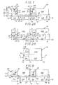
Les objets de l'invention, leurs caractéristiques et leurs avantages, ressortiront d'ailleurs de la description qui va suivre, à titre d'exemple, en référence aux dessins schématiques annexés sur lesquels:
- la figure 1 est une vue partielle en plan d'un flan suivant l'invention;
- les figures 2A, 2B sont des vues partielles en plan analogues à celle de la figure 1 et illustrent diverses phases du pliage du flan concerné conduisant à la réalisation d'une ébauche d'emballage suivant l'invention;
- les figures 3A, 3B sont des vues partielles en perspective illustrant diverses phases de la fermeture de l'emballage issu d'une telle ébauche;
- la figure 4 est une vue partielle en perspective de cet emballage, vu de l'intérieur, une fois cet emballage fermé;
- la figure 5 en est, à l'échelle supérieure, une vue partielle en coupe transversale, suivant la ligne V-V de la figure 4;
- la figure 6 est une vue partielle en perspective de l'emballage suivant l'invention ainsi fermé;
- la figure 7 est une vue partielle en perspective illustrant l'ouverture de l'emballage suivant l'invention;
- la figure 8 est une vue partielle en perspective illustrant sa refermeture;
- la figure 9 est une vue analogue à celle de la figure 1 et se rapporte à une variante de réalisation.
- Figure 1 is a partial plan view of a blank according to the invention;
- FIGS. 2A, 2B are partial plan views similar to that of FIG. 1 and illustrate various phases of the folding of the blank concerned, leading to the production of a packaging blank according to the invention;
- Figures 3A, 3B are partial perspective views illustrating various phases of the closure of the packaging from such a blank;
- Figure 4 is a partial perspective view of this package, seen from the inside, once this package closed;
- Figure 5 is a larger scale, a partial view in cross section along the line VV of Figure 4;
- Figure 6 is a partial perspective view of the packaging according to the invention thus closed;
- Figure 7 is a partial perspective view illustrating the opening of the packaging according to the invention;
- Figure 8 is a partial perspective view illustrating its reclosure;
- Figure 9 is a view similar to that of Figure 1 and relates to an alternative embodiment.
D'une manière générale, et tel qu'illustré sur ces figures, un flan 10 suivant l'invention est du genre comportant, d'un seul tenant, pour la constitution d'un emballage sur lequel doit être rapportée de manière indépendante une poignée 11, une pluralité de panneaux de côté 12 successivement articulés deux à deux par des lignes de pliage parallèles 13, dites ci-après par simple commodité lignes de pliage principales.In general, and as illustrated in these figures, a blank 10 according to the invention is of the type comprising, in one piece, for the constitution of a package to which a handle must be attached independently. 11, a plurality of
Dans les formes de réalisation plus particulièrement représentées, l'emballage recherché devant avoir en section transversale un contour quadrangulaire, quatre panneaux de côté 12 sont prévus, à savoir deux panneaux de côté de plus petite largeur 12A, et deux panneaux de côté de plus grande largeur 12B, qui alternent avec les précédents.In the embodiments more particularly shown, the desired packaging having to have in cross section a quadrangular contour, four
En pratique, chacun de ces panneaux de côté 12A, 12B est globalement quadrangulaire.In practice, each of these
Au-delà d'une ligne de pliage 14 parallèle aux lignes de pliage principales 13, l'un des panneaux de côté 12 extrêmes, et il s'agit en l'espèce d'un panneau de côté de plus grande largeur 12B, se prolonge, de manière connue en soi, et pour des raisons qui apparaîtront ci-après, par une bande de solidarisation 15.Beyond a
Le long d'un des bords longitudinaux de l'alignement qu'ils forment, certains au moins des panneaux de côté 12 se prolongent, chacun individuellement, au-delà de lignes de pliage racines 15 perpendiculaires aux lignes de pliage principales 13, par des rabats 18.Along one of the longitudinal edges of the alignment which they form, at least some of the
Dans les formes de réalisation représentées, il y a ainsi, en pratique, un rabat 18 pour chacun des panneaux de côté 12, respectivement 18A pour les panneaux de côté 12A, et 18B pour les panneaux de côté 12B.In the embodiments shown, there is thus, in practice, a
Leur longueur est adaptée à la largeur de ceux-ci.Their length is adapted to the width of these.
Leur hauteur, par contre, est sensiblement la même pour tous.Their height, on the other hand, is roughly the same for all.
Comme les panneaux de côté 12, ils sont tous globalement quadrangulaires.Like the
Par ailleurs, et de manière connue en soi, une bande détachable 27, délimitée par des lignes de prédécoupage 28, est prédécoupée en continuité dans certains au moins, successifs, des panneaux de côté 12, parallèlement aux lignes de pliage racines 16 des rabats 18 prolongeant ceux-ci, à proximité desdites lignes de pliage racines 16.Furthermore, and in a manner known per se, a
En pratique, une telle bande détachable 27 af- fectetrois panneaux de côté 12 successifs, à savoir les deux panneaux de côté de moindre largeur 12A, et le panneau de plus grande largeur 12B encadré par ceux-ci; elle affecte également la bande de solidarisation 15.In practice, such a
Suivant l'invention, dans chacun de deux rabats 18 prolongeant deux panneaux de côté 12 destinés à former des panneaux de côté opposés pour l'emballage recherché, et il s'agit, dans les formes de réalisation représentées, des rabats 18A prolongeant les panneaux de côté de moindre largeur 12A, est découpée une languette 20 issue elle-même d'une ligne de pliage racine 21 perpendiculaire aux lignes de pliage principales 13, et dont la longueur Li, mesurée perpendiculairement à compter d'une ligne de pliage superposable à la ligne de pliage racine 16 du rabat 18A correspondant ou confondue avec celle-ci, est supérieure à celle L2 à laquelle est établie, par rapport à ladite ligne de pliage racine 16, celle des lignes de prédécoupage 28 de la bande détachable 27 qui est la plus proche de ladite ligne de pliage racine 16.According to the invention, in each of two
Dans la forme de réalisation plus particulièrement illustrée par les figures 1 à 8, la ligne de pliage racine 21 d'une languette 20 suivant l'invention est distincte de la ligne de pliage racine 16 du rabat 18A dans lequel cette languette 20 est découpée, elle s'étend sensiblement parallèlement à celle-ci, et, à une distance D1 d'elle sensiblement égale à celle D2 la séparant de ladite ligne de pliage racine 16, ladite languette 20 est affectée d'une ligne de pliage 24, qui est sensiblement parallèle aux deux précédentes, mais dont le sens de pliage est inverse de celui de celles-ci.In the embodiment more particularly illustrated by FIGS. 1 to 8, the
Cette ligne de pliage 24 est donc superposable à la ligne de pliage racine 16 du rabat 18A correspondant, et c'est à compter d'elle, dans cette forme de réalisation, qu'est mesurée la longueur L, précisée ci-dessus, de la portion concernée d'une languette 20.This
Dans la forme de réalisation représentée, une telle ligne de pliage 24 est matérialisée par une découpe en boutonnière 25 dans sa zone médiane, pour en faciliter le pliage correspondant.In the embodiment shown, such a
Par ailleurs, dans la forme de réalisation illustrée par les figures 1 à 8, la languette 20 ainsi découpée dans un rabat 18A s'étend le long d'un des côtés de celui-ci, ledit côté étant celui le plus proche du rabat 18B encadré par les rabats 18A dans lesquels est découpée une telle languette 20.Furthermore, in the embodiment illustrated in FIGS. 1 to 8, the
Autrement dit, dans cette forme de réalisation, les languettes 20 des rabats 18A sont établies symétriquement de part et d'autre du rabat 18B encadré par ces rabats 18A, au plus près de ce rabat 18B.In other words, in this embodiment, the
Conjointement, dans la forme de réalisation illustrée parles figures 1 à 8, au sein d'une languette 20 suivant l'invention, se trouve individualisée, par une ligne de prédécoupage 22, une portion détachable 23 implantée de manière à pouvoir se superposer au panneau de côté 12 considéré lorsque, tel qu'it apparaîtra ci-après, ladite languette 20 est rabattue sur celui-ci par pliage autour de sa ligne de pliage racine 21.At the same time, in the embodiment illustrated in FIGS. 1 to 8, within a
En pratique, dans la forme de réalisation représentée, la portion détachable 23 d'une languette 20 suivant l'invention forme un prolongement latéral de celle-ci, de manière à se situer sensiblement au droit de l'axe médian du panneau de côté 12A correspondant.In practice, in the embodiment shown, the
En outre, dans cette forme de réalisation, la portion détachable 23 d'une languette 20 suivant l'invention est sensiblement en équerre par rapport à la partie courante de celle-ci, à l'extrémité de cette languette 20 la plus éloignée de sa ligne de pliage racine 21, et la ligne de prédécoupage 22 qui la délimite est sensiblement oblique vis-à-vis de ladite ligne de pliage racine 21.In addition, in this embodiment, the
Quoi qu'il en soit, la portion détachable 23 que présente ainsi une languette 20 suivant l'invention est globalement située à une distance L'1 de la ti- gne de pliage 24 de cette languette 20 au moins égale à la distance L'z à laquelle est établie, par rapport à la ligne de pliage racine 16 concernée, celle des lignes de prédécoupage 28 de la bande détachable 27 qui est la plus éloignée de ladite ligne de pliage racine 16.Anyway, the
Par ailleurs, sur la face interne des panneaux de côté 12, une bande de renfort 29 est superposée en continu à la bande détachable 27, dans la zone médiane de celle-ci.Furthermore, on the internal face of the
Pour des raisons de commodité de pose, cette bande détachable 27 s'étend sur la totalité des panneaux de côté 12, perpendiculairement aux lignes de pliage principales 13.For reasons of installation convenience, this
En pratique, elle se trouve cependant interrompue, par exemple par une entaille 30, tel que représenté, au droit de celle des lignes de pliage principales 13 par laquelle l'un des panneaux de côté 12A prolongés par un rabat 18A dans lequel est découpée une languette 20 se raccorde à un panneau de côté 12B prolongé par un rabat 18B dépourvu d'une telle languette.In practice, it is however interrupted, for example by a
Le long de l'autre des bords longitudinaux de l'alignement qu'ils forment, les panneaux de côté 12 peuvent également être chacun individuellement prolongés, au-delà de lignes de pliage racines perpendiculaires aux lignes de pliage principales 13, par des rabats propres à former conjointement un fond pour l'emballage recherché. Il peut s'agir par exemple de rabats du type de ceux décrits ci-dessus, mais sans languette suivant l'invention.Along the other of the longitudinal edges of the alignment they form, the
En variante, il peut s'agir de rabats propres à la constitution d'un fond automatique.Alternatively, it may be flaps specific to the constitution of an automatic background.
En variante, également, un fond indépendant peut être prévu.Alternatively, also, an independent background can be provided.
Ces diverses dispositions sont bien connues par elles-mêmes et, ne relevant pas de la présente invention, elles ne seront pas décrites plus en détail ici.These various arrangements are well known in themselves and, not pertaining to the present invention, they will not be described in more detail here.
C'est en outre la raison pour laquelle elles n'ont pas été représentées sur les figures.This is also the reason why they have not been shown in the figures.
Quoi qu'il en soit, et de manière également connue en soi, le flan 10 suivant l'invention peut aisément être réalisé en carton, carton ondulé, ou autre matériau en feuille convenablement découpé et rainé, ses lignes de rainage en constituant les lignes de pliage, et également les lignes de prédécoupage lorsque, de place en place, elles sont suffisamment accentuées pour le traverser de part en part.Anyway, and in a manner also known per se, the blank 10 according to the invention can easily be made of cardboard, corrugated cardboard, or other sheet material suitably cut and grooved, its crease lines constituting the lines of folding, and also the precut lines when, from place to place, they are sufficiently accentuated to cross it right through.
Avant le pliage du flan 10 suivant l'invention, certaines des portions en sont encollées, tel que schématisé par des hachures sur la figure 1.Before folding the blank 10 according to the invention, some of the portions are glued therefrom, as shown diagrammatically by hatching in FIG. 1.
Il s'agit, tout d'abord, des portions détachables 23 des languettes 20 suivant l'invention.These are, first of all,
II s'agit, ensuite, de la partie des rabats 18A qui, située entre la ligne de pliage racine 16 d'un tel rabat 18A et la ligne de pliage racine 21 de la languette 20 découpée dans celui-ci, est dans le prolongement de la partie courante de cette languette 20.It is, then, the part of the
Il s'agit enfin, de préférence, et tel que représenté, d'une portion, de hauteur inférieure à L2, des languettes 20 au-delà de leur ligne de pliage 24, à compter de celle-ci en direction de leur extrémité.Finally, it is preferably, and as shown, a portion, of height less than L 2 , of the
Après un tel encollage, les languettes 20 sont rabattues sur les panneaux de côté 12A, par pliage de 180° autour de leur ligne de pliage racine 21, figure 2A.After such gluing, the
Au terme de ce rabattement, les lignes de pliage racines 21 des languettes 20 sont superposées aux lignes de pliage racines 16 des rabats 18A correspondants, et, compte tenu des valeurs relatives des longueurs L1, L2, L'1, L'2 précisées ci-dessus, les portions détachables 23 des languettes 20 se trouvent superposées aux panneaux de côté 12A, sur la face interne de ceux-ci, en dessous de la bande détachable 27, dans la zone médiane desdits panneaux de côté 12A.At the end of this folding, the
Elles y sont en outre solidarisées par collage.They are also joined together by gluing.
Conjointement, la portion des languettes 20 comprise entre leur ligne de pliage 24 et leur ligne de pliage racine 21 se trouve solidarisée par collage au rabat 18A concerné sur la face interne de celui-ci.Jointly, the portion of the
Enfin, par leur portion située au-delà de leur ligne de pliage 24, au voisinage de celle-ci, les languettes 20 se trouvent solidarisées par collage aux panneaux de côté 12A correspondants, au-dessus de la bande détachable 27, c'est-à-dire entre ladite bande détachable 27 et la ligne de pliage racine 16 correspondante.Finally, by their portion located beyond their
Il est procédé ensuite au rabattement du panneau de côté 12B extrême, par pliage de 180° de celui-ci autour de la ligne de pliage principale 13 qui le relie au panneau de côté 12A adjacent, puis, après collage de la bande de solidarisation 15, au rabattement du panneau de côté 12A extrême, par pliage de 180° de celui-ci autour de la ligne de pliage principale 13 qui le relie au panneau de côté 12B adjacent, figure 2B.The
Au terme du pliage en fourreau tubulaire ainsi appliqué au flan 10 suivant l'invention, les deux panneaux de côté extrêmes 12A, 12B de celui-ci se trouvent solidarisés l'un à l'autre, par la bande de solidarisation 15 prévue à cet effet.At the end of the folding into a tubular sheath thus applied to the blank 10 according to the invention, the two
L'ébauche tubulaire d'emballage 32 ainsi obtenue est, de manière connue en soi, avantageusement livrable à plat.The tubular packaging blank 32 thus obtained is, in a manner known per se, advantageously deliverable flat.
Pour les raisons exposées ci-dessus, elle comporte, suivant l'invention, solidarisée par avance à chacun de deux panneaux de côté 12A opposés, la portion détachable 23 de la languette 20 correspondante.For the reasons explained above, it comprises, according to the invention, secured in advance to each of two
En outre, par sa portion comprise entre sa ligne de pliage racine 21 et sa ligne de pliage 24, une telle languette 20 s'y trouve solidarisée au rabat 18A dans lequel elle est découpée, et, par sa portion située au-delà de sa ligne de pliage 24, au voisinage de celle-ci, elle se trouve solidarisée au panneau de côté 12A correspondant, au-dessus de la bande détachable 27.In addition, by its portion between its
Pour mise en volume d'une telle ébauche tubulaire d'emballage 32, il suffit, de manière connue en soi, d'exercer suivant les flèches F de la figure 2B une action de poussée sur ses lignes de pliage principales 13 opposées.For volume of such a tubular packaging blank 32, it suffices, in a manner known per se, to exert, according to the arrows F in FIG. 2B, a pushing action on its opposite main fold lines 13.
Sur l'emballage 34 ainsi obtenu, il est alors procédé à la pose de la poignée 11.On the
Pour l'implantation d'unetelle poignée 11, l'emballage 34 présente avantageusement, par avance, un renfort local sur la face interne de chacun de ses deux panneaux de côté 12A opposés sur lesquels doit se faire une telle implantation.For the implantation of such a
Il s'agit de la portion détachable 23 de la languette 20 provenant du rabat 18A correspondant.It is the
De manière connue en soi, et tel qu'il est mieux visible à la figure 5, la pose de la poignée 11 peut par exemple se faire à l'aide de rivets 35, un pour chacune de ses extrémités pour en autoriser un tourillonnement autour de ceux-ci.In a manner known per se, and as it is better visible in FIG. 5, the fitting of the
Après fermeture du fond de l'emballage 34, et remplissage de celui-ci, il est procédé à la superposition deux à deux de ses rabats 18, par pliage en équerre de ceux-ci autour de leur ligne de pliage racine 16, lesdits rabats 18 étant préalablement encollés pour se solidariser deux à deux les uns aux autres, figure 3B.After closing the bottom of the
En pratique, le rabat 18B prolongeant le panneau de côté 12B extrême, qui est celui au droit d'une des lignes de pliage principales 13 duquel se trouve l'entaille 30 interrompant localement la bande de renfort 29, est rabattu le dernier, et forme dès lors le dessus de l'emballage 34.In practice, the
Pour accès au contenu de celui-ci, il est procédé à l'élimination de la bande détachable 27, ce qui conduit à décapiter sur trois côtés le corps 36 de cet emballage.To access the content thereof, the
Seul demeure articulé à ce dernier le rabat 18B qui en forme le dessus, avec, solidarisés par collage à celui-ci, les autres rabats 18, l'ensemble constituant un couvercle 37 avec les parties détachées des panneaux de côté 12.The only flap hinged to the latter is the
Il suffit, ensuite, à la faveur de la fente le séparant du corps 36, d'exercer une traction sur ce couvercle 37, pour assurer le détachement vis-à-vis de lui, par les lignes de prédécoupage 22, de la portion détachable 23 des languettes 20 qui lui demeurent solidaires, et ainsi en permettre effectivement le rabattement nécessaire à son ouverture, figure 7.It then suffices, by means of the slot separating it from the
Suivant l'invention, et compte tenu de valeurs relatives des longueurs L,, L2 précisées ci-dessus, les languettes 20 forment alors, par leur partie restante, en saillie sur le rabat 18B concerné ou, autrement dit, sur le couvercle 37 à la constitution duquel celui-ci participe, des pattes 39 qui, disposées chacune respectivement latéralement le long des bords d'un tel couvercle 37, dans les zones d'angle de celui-ci opposées à la charnière par laquelle il est articulé au corps 36, sont aptes à s'engager dans ce corps 36, au contact des panneaux de côté 12A correspondants, et ainsi permettre la refermeture du corps 36, figure 8.According to the invention, and taking into account the relative values of the lengths L ,, L 2 specified above, the
Dans la variante de réalisation illustrée par la figure 9, aucun renfort local des panneaux de côté 12A n'est prévu pour l'implantation d'une poignée, soit qu'un tel renfort local soit assuré autrement, soit qu'un autre type de poignée soit adopté.In the alternative embodiment illustrated in FIG. 9, no local reinforcement of the
Les languettes 20 suivant l'invention ne comportent donc pas de portion détachable.The
En outre, dans cette variante de réalisation, la ligne de pliage racine d'une telle languette 20 est confondue avec la ligne de pliage racine 16 du rabat 18A dans lequel elle est découpée, et c'est donc à compter de cette ligne de pliage racine 16 qu'est mesurée la longueur L, à prendre en considération.Furthermore, in this alternative embodiment, the root fold line of such a
Enfin, dans cette variante de réalisation, les languettes 20 suivant l'invention s'étendent dans la partie médiane des rabats 18A concernés.Finally, in this variant embodiment, the
Bien entendu, la présente invention ne se limite pas aux formes de réalisation décrites et représentées, mais englobe toute variante d'exécution et/ou de combinaison de leurs divers éléments.Of course, the present invention is not limited to the embodiments described and shown, but encompasses any variant embodiment and / or combination of their various elements.
En particulier, les rôles respectifs des panneaux de côté de plus grande largeur et de ceux de plus petite largeur, et, avec eux, des rôles respectifs des rabats correspondants, peuvent être intervertis.In particular, the respective roles of the side panels of greater width and those of smaller width, and, with them, respective roles of the corresponding flaps, can be reversed.
En outre, l'application de l'invention n'est pas limitée aux seuls emballages dont la section transversale est quadrangulaire, mais peut aussi bien s'envisager par exemple pour les emballages dont la section transversale est hexagonale.In addition, the application of the invention is not limited to only packages whose cross section is quadrangular, but can also be envisaged for example for packages whose cross section is hexagonal.
Claims (16)
Applications Claiming Priority (2)
| Application Number | Priority Date | Filing Date | Title |
|---|---|---|---|
| FR8300776A FR2539393A1 (en) | 1983-01-19 | 1983-01-19 | FLAN FOR THE CONSTITUTION OF A PACKAGE ON WHICH MUST BE RECORDED A HANDLE, AND DRAFT PACKING AND PACKAGING CORRESPONDING |
| FR8300776 | 1983-01-19 |
Publications (3)
| Publication Number | Publication Date |
|---|---|
| EP0114772A2 EP0114772A2 (en) | 1984-08-01 |
| EP0114772A3 EP0114772A3 (en) | 1984-08-08 |
| EP0114772B1 true EP0114772B1 (en) | 1986-06-04 |
Family
ID=9285076
Family Applications (2)
| Application Number | Title | Priority Date | Filing Date |
|---|---|---|---|
| EP19840400109 Expired EP0114772B1 (en) | 1983-01-19 | 1984-01-19 | Blank for making a package provided with a handle, and corresponding preformed package and package |
| EP19840400108 Expired EP0114771B1 (en) | 1983-01-19 | 1984-01-19 | Blank for making a package provided with a handle, and corresponding preformed package and package |
Family Applications After (1)
| Application Number | Title | Priority Date | Filing Date |
|---|---|---|---|
| EP19840400108 Expired EP0114771B1 (en) | 1983-01-19 | 1984-01-19 | Blank for making a package provided with a handle, and corresponding preformed package and package |
Country Status (4)
| Country | Link |
|---|---|
| EP (2) | EP0114772B1 (en) |
| DE (2) | DE3461909D1 (en) |
| ES (2) | ES285499Y (en) |
| FR (1) | FR2539393A1 (en) |
Families Citing this family (8)
| Publication number | Priority date | Publication date | Assignee | Title |
|---|---|---|---|---|
| DE8511805U1 (en) * | 1985-04-20 | 1985-05-30 | Henkel KGaA, 4000 Düsseldorf | Tear device for opening a package |
| FR2639917B1 (en) * | 1988-12-02 | 1991-03-15 | Nicollet Hugues Sa | PARALLELEPIPEDIC PACKAGING WITH CLOSABLE LID, BLANK SPECIFICALLY FORMING SUCH A PACKAGING, AND CORRESPONDING PACKAGING BLANK |
| DE3844483C1 (en) * | 1988-12-31 | 1989-08-17 | Henkel Kgaa, 4000 Duesseldorf, De | |
| FR2653748B1 (en) * | 1989-10-31 | 1992-02-07 | Nicollet Hugues Sa | CARDBOARD STRAP, CORRUGATED PAPERBOARD OR OTHER SUITABLE SHEET AND FOLDED SHEET MATERIAL, AND PACKAGING EQUIPPED WITH SUCH A STRAP FOR THE CONSTRUCTION OF A HANDLE. |
| US5209394A (en) * | 1989-12-29 | 1993-05-11 | Lever Brothers Company | Carton for detergent |
| US5320279A (en) * | 1989-12-29 | 1994-06-14 | Lever Brothers Company, Division Of Conopco, Inc. | Carton for concentrated detergent |
| US5431334A (en) * | 1994-05-31 | 1995-07-11 | Roberts Systems, Inc. | Slide weld handle |
| FR2767788B1 (en) * | 1997-09-03 | 1999-11-26 | Cartonneries Tailleur | OPENING SYSTEM AND PACKAGE COMPRISING SAME |
Family Cites Families (2)
| Publication number | Priority date | Publication date | Assignee | Title |
|---|---|---|---|---|
| US2836343A (en) * | 1956-05-28 | 1958-05-27 | Fund Del Inc | Tear strip means for opening cartons and the like |
| DE2838356A1 (en) * | 1978-09-02 | 1980-03-20 | Henkel Kgaa | Folded carrier bag with glued joints - has stiffened vertical corners produced by folding of flat cardboard |
-
1983
- 1983-01-19 FR FR8300776A patent/FR2539393A1/en active Granted
-
1984
- 1984-01-18 ES ES1984285499U patent/ES285499Y/en not_active Expired
- 1984-01-18 ES ES1984285500U patent/ES285500Y/en not_active Expired
- 1984-01-19 DE DE8484400108T patent/DE3461909D1/en not_active Expired
- 1984-01-19 EP EP19840400109 patent/EP0114772B1/en not_active Expired
- 1984-01-19 EP EP19840400108 patent/EP0114771B1/en not_active Expired
- 1984-01-19 DE DE8484400109T patent/DE3460181D1/en not_active Expired
Also Published As
| Publication number | Publication date |
|---|---|
| ES285499U (en) | 1986-02-01 |
| EP0114771A3 (en) | 1984-08-22 |
| DE3461909D1 (en) | 1987-02-12 |
| EP0114772A2 (en) | 1984-08-01 |
| DE3460181D1 (en) | 1986-07-10 |
| FR2539393B1 (en) | 1985-05-17 |
| EP0114771A2 (en) | 1984-08-01 |
| FR2539393A1 (en) | 1984-07-20 |
| EP0114772A3 (en) | 1984-08-08 |
| ES285500U (en) | 1986-02-01 |
| ES285500Y (en) | 1986-09-01 |
| EP0114771B1 (en) | 1987-01-07 |
| ES285499Y (en) | 1986-09-01 |
Similar Documents
| Publication | Publication Date | Title |
|---|---|---|
| EP0443930B1 (en) | Package made of cardboard, corrugated cardboard or other conveniently cut and folded sheet material, with a reclosable cover provided with a handle, and corresponding blank or blanks | |
| EP0114772B1 (en) | Blank for making a package provided with a handle, and corresponding preformed package and package | |
| EP0904235B1 (en) | Method for producing a package with nesting lid from a blank | |
| FR2609965A1 (en) | Package of the box type, in particular a vegetable box made of cardboard, corrugated cardboard or other sheet material | |
| EP0454506A1 (en) | Package made from cardboard, corrugated cardboard or other conveniently cut and folded sheet material, with an interengageable reclosable cover, and corresponding blank | |
| FR2686316A1 (en) | Package made of cardboard, corrugated cardboard or other sheet material, suitably cut out and folded, with a lid which can be re-closed by engagement, and corresponding blank or blanks | |
| EP0785138B1 (en) | Blanks assembly for packing case in the form of a display and case obtained from such assembly | |
| FR2861370A1 (en) | Packaging case for use in bakery, has lateral branches and thumb tab that are delimited by two recesses so as to allow tab to move from branches by deformation and overlap opposite wall | |
| EP1348635B1 (en) | Blank for package out of semi-rigid material comprising on one surface a heat shrinkable film | |
| FR2662141A1 (en) | Package made of cardboard, corrugated cardboard or other sheet material suitably cut out and folded, with a re-closable lid, and corresponding blank or blanks | |
| FR2653747A1 (en) | Package with strap forming a handle, made from cardboard, corrugated cardboard or other sheet material suitably cut out and folded, and corresponding blank | |
| FR2634456A1 (en) | Package with a handle and blank capable of making such a package | |
| FR2639917A1 (en) | Parallelepipedal package having a closable lid, blank suitable for forming such a package, and corresponding packaging preform | |
| FR2607111A1 (en) | Blank for the construction of a closable package, and corresponding packaging carcass and package | |
| FR2590549A1 (en) | Package for heavy items having a point, for example an iron, blank suitable for constituting such a package, and corresponding preliminary package. | |
| FR2658482A1 (en) | Package made of cardboard, corrugated cardboard or other sheet material, suitably cut out and folded, and having a lid provided with a handle and which is re-closable, and corresponding blank or blanks | |
| FR2542711A1 (en) | Cardboard package with spout | |
| FR2740112A1 (en) | Box with integral wedge formed from folded sheet | |
| FR2543916A1 (en) | Package with a handle, made of cardboard, corrugated cardboard or other sheet material | |
| FR2778635A1 (en) | Cardboard packaging transformable into display shelf | |
| FR2463064A1 (en) | Rectangular packing carton with integral end lid - is closed by tongue passing through lid and folded end flap on lid | |
| CA1269078A (en) | Unit packaging for glass and like articles | |
| FR2525560A1 (en) | Corrugated cardboard package box - with parallel folding lines and a joining flap and gripping handle strip | |
| FR2634464A1 (en) | Package with a pouring opening and blank capable of making such a package | |
| FR2493271A1 (en) | Handled flap for cardboard package - has slits formed in blank to form central strap which extends partly onto tab at each end |
Legal Events
| Date | Code | Title | Description |
|---|---|---|---|
| PUAI | Public reference made under article 153(3) epc to a published international application that has entered the european phase |
Free format text: ORIGINAL CODE: 0009012 |
|
| PUAL | Search report despatched |
Free format text: ORIGINAL CODE: 0009013 |
|
| AK | Designated contracting states |
Designated state(s): BE DE FR GB IT NL |
|
| AK | Designated contracting states |
Designated state(s): BE DE FR GB IT NL |
|
| 17P | Request for examination filed |
Effective date: 19840927 |
|
| GRAA | (expected) grant |
Free format text: ORIGINAL CODE: 0009210 |
|
| AK | Designated contracting states |
Kind code of ref document: B1 Designated state(s): BE DE FR GB IT NL |
|
| REF | Corresponds to: |
Ref document number: 3460181 Country of ref document: DE Date of ref document: 19860710 |
|
| ITF | It: translation for a ep patent filed | ||
| PLBE | No opposition filed within time limit |
Free format text: ORIGINAL CODE: 0009261 |
|
| STAA | Information on the status of an ep patent application or granted ep patent |
Free format text: STATUS: NO OPPOSITION FILED WITHIN TIME LIMIT |
|
| 26N | No opposition filed | ||
| ITTA | It: last paid annual fee | ||
| PGFP | Annual fee paid to national office [announced via postgrant information from national office to epo] |
Ref country code: NL Payment date: 19930131 Year of fee payment: 10 |
|
| PG25 | Lapsed in a contracting state [announced via postgrant information from national office to epo] |
Ref country code: NL Effective date: 19940801 |
|
| NLV4 | Nl: lapsed or anulled due to non-payment of the annual fee | ||
| PGFP | Annual fee paid to national office [announced via postgrant information from national office to epo] |
Ref country code: BE Payment date: 19961203 Year of fee payment: 14 |
|
| PGFP | Annual fee paid to national office [announced via postgrant information from national office to epo] |
Ref country code: GB Payment date: 19970117 Year of fee payment: 14 |
|
| PGFP | Annual fee paid to national office [announced via postgrant information from national office to epo] |
Ref country code: DE Payment date: 19970325 Year of fee payment: 14 |
|
| PG25 | Lapsed in a contracting state [announced via postgrant information from national office to epo] |
Ref country code: GB Free format text: LAPSE BECAUSE OF NON-PAYMENT OF DUE FEES Effective date: 19980119 |
|
| PG25 | Lapsed in a contracting state [announced via postgrant information from national office to epo] |
Ref country code: BE Free format text: LAPSE BECAUSE OF NON-PAYMENT OF DUE FEES Effective date: 19980131 |
|
| BERE | Be: lapsed |
Owner name: HUGUES NICOLLET S.A. Effective date: 19980131 |
|
| GBPC | Gb: european patent ceased through non-payment of renewal fee |
Effective date: 19980119 |
|
| PG25 | Lapsed in a contracting state [announced via postgrant information from national office to epo] |
Ref country code: DE Free format text: LAPSE BECAUSE OF NON-PAYMENT OF DUE FEES Effective date: 19981001 |
|
| PGFP | Annual fee paid to national office [announced via postgrant information from national office to epo] |
Ref country code: FR Payment date: 19991028 Year of fee payment: 17 |
|
| PG25 | Lapsed in a contracting state [announced via postgrant information from national office to epo] |
Ref country code: FR Free format text: LAPSE BECAUSE OF NON-PAYMENT OF DUE FEES Effective date: 20010928 |
|
| REG | Reference to a national code |
Ref country code: FR Ref legal event code: ST |