EP0113440B1 - Elektromagnetisches Relais - Google Patents
Elektromagnetisches Relais Download PDFInfo
- Publication number
- EP0113440B1 EP0113440B1 EP83112209A EP83112209A EP0113440B1 EP 0113440 B1 EP0113440 B1 EP 0113440B1 EP 83112209 A EP83112209 A EP 83112209A EP 83112209 A EP83112209 A EP 83112209A EP 0113440 B1 EP0113440 B1 EP 0113440B1
- Authority
- EP
- European Patent Office
- Prior art keywords
- contact
- relay
- counter
- armature
- counter contact
- Prior art date
- Legal status (The legal status is an assumption and is not a legal conclusion. Google has not performed a legal analysis and makes no representation as to the accuracy of the status listed.)
- Expired
Links
- 238000005192 partition Methods 0.000 claims description 3
- 230000015572 biosynthetic process Effects 0.000 claims 1
- 238000007373 indentation Methods 0.000 claims 1
- 230000013011 mating Effects 0.000 description 8
- 230000007717 exclusion Effects 0.000 description 2
- XEEYBQQBJWHFJM-UHFFFAOYSA-N Iron Chemical group [Fe] XEEYBQQBJWHFJM-UHFFFAOYSA-N 0.000 description 1
- 238000005452 bending Methods 0.000 description 1
- 238000011161 development Methods 0.000 description 1
- 230000018109 developmental process Effects 0.000 description 1
- 238000009413 insulation Methods 0.000 description 1
- 238000000034 method Methods 0.000 description 1
- 238000004804 winding Methods 0.000 description 1
Images

Classifications
-
- H—ELECTRICITY
- H01—ELECTRIC ELEMENTS
- H01H—ELECTRIC SWITCHES; RELAYS; SELECTORS; EMERGENCY PROTECTIVE DEVICES
- H01H50/00—Details of electromagnetic relays
- H01H50/54—Contact arrangements
- H01H50/60—Contact arrangements moving contact being rigidly combined with movable part of magnetic circuit
-
- H—ELECTRICITY
- H01—ELECTRIC ELEMENTS
- H01H—ELECTRIC SWITCHES; RELAYS; SELECTORS; EMERGENCY PROTECTIVE DEVICES
- H01H50/00—Details of electromagnetic relays
- H01H50/54—Contact arrangements
- H01H50/546—Contact arrangements for contactors having bridging contacts
-
- H—ELECTRICITY
- H01—ELECTRIC ELEMENTS
- H01H—ELECTRIC SWITCHES; RELAYS; SELECTORS; EMERGENCY PROTECTIVE DEVICES
- H01H1/00—Contacts
- H01H1/12—Contacts characterised by the manner in which co-operating contacts engage
- H01H1/14—Contacts characterised by the manner in which co-operating contacts engage by abutting
- H01H1/20—Bridging contacts
- H01H1/2075—T-shaped bridge; bridging contact has lateral arm for mounting resiliently or on a pivot
-
- H—ELECTRICITY
- H01—ELECTRIC ELEMENTS
- H01H—ELECTRIC SWITCHES; RELAYS; SELECTORS; EMERGENCY PROTECTIVE DEVICES
- H01H1/00—Contacts
- H01H1/12—Contacts characterised by the manner in which co-operating contacts engage
- H01H1/14—Contacts characterised by the manner in which co-operating contacts engage by abutting
- H01H1/24—Contacts characterised by the manner in which co-operating contacts engage by abutting with resilient mounting
- H01H2001/247—Contacts characterised by the manner in which co-operating contacts engage by abutting with resilient mounting using an elastic hinge, the contact being composed of rigid parts connected by thinned flexible hinge parts
Definitions
- the invention relates to an electromagnetic relay with a coil body serving as a support for the relay, an angled yoke, the first leg of which is coupled to a first pole end of a coil core and the second leg of which forms a bearing edge for a flat armature which forms a working air gap with the second pole end of the coil core forms, wherein a contact spring connected to the armature extends beyond its free end into a molded contact pocket on the coil former and connects there as a contact bridge, at least in a switch position, in alignment with one another, with the bearing axis of the armature or the contact spring being perpendicular to the exclusion plane of the relay .
- the object of the invention is therefore to provide a relay of the type mentioned, in which a bridge contact arrangement is formed with as few and simple parts as possible, in which the contact pressure is the same at all contact points and which without design changes by corresponding use of contact elements as a bridge closer , can be designed as a bridge opener and as a bridge switch.
- this object is achieved in that the two counter-contact elements carrying both the counter-contact pieces and the exclusion parts (16c, 17c) are flat plates which are anchored in the carrier and are parallel to one another and in a common plane, and in that the counter-piece (16b) carries End of the one counter-contact element is a cross leg lying in the common plane and carrying the counterpart (17b) carrying the end of the other counter-contact element.
- the two mating contact elements Due to the angular shape of the first mating contact element designed as a flat section, it is possible to arrange the two mating contact elements to be contacted jointly by the bridge contact spring with the required distance and still arrange the contact points of the two mating contact elements so that both are at the same distance from the pivot axis of the bridge contact spring and thus get the same contact pressure.
- the relay shown in FIGS. 1 to 3 has a coil body 1 with a winding 2, which is applied between the flanges 3 and 4.
- An iron core 5 is arranged in the coil body 1 along the coil axis and is connected at one end 5a to the first leg 6a of an angular yoke 6.
- the other end 5b of the core serves as a pole face and forms a working air gap with an armature 7, which lies with an extension 7a in a recess 6c of the second yoke leg 6b and is mounted on a bearing cutting edge 6d.
- the armature By means of a return spring in the form of a helical spring 8, the armature is pulled into its rest position, while when the relay responds, it is attracted to the core end 5b against the force of the spring 8 and thereby switches the bridge contact spring 9 attached to it.
- the relay corresponds to a known structure.
- the contact arrangement is arranged in a contact pocket 10, this contact pocket being formed in one piece with the coil former by an extension 11 on the coil former flange 4.
- Four receiving slots 12, 13, 14 and 15 are provided in the contact pocket for receiving counter-contact elements.
- only the receiving slots 12 and 13 are equipped with counter-contact elements 16 and 17, while the opposite receiving slots 14 and 15 remain free.
- the relay shown is thus designed as a bridge closer, since the rest side of the bridge contact spring 9 is not equipped.
- the receiving slots 14 and 15, which are not used in all embodiments, are expediently closed by thin mold partitions, which are only pierced through the inserted connecting pin of the mating contact elements when these receiving slots are fitted.
- the short counter-contact element 17 carries a contact rivet 17b at its free end 17a, while the longer counter-contact element 16 has a cross leg 16a at its free end, which projects beyond the free end 17a of the other contact element and carries a contact rivet 16b in the area above the second counter-contact element 17 .
- the two counter-contact elements 16 and 17 are thus entirely in one Level, with their two contact rivets 16b and 17b being at the same distance from the pivot axis of the bridge contact spring 9, so that when the armature 7 is tightened, both contact rivets 16b and 17b simultaneously come into contact with the contact rivets 9a and 9b of the bridge contact piece 9c and through the torsional contact spring 9 with the same contact pressure.
- the connecting pins 16c and 17c of the mating contact elements 16 and 17 are designed in such a way that they are as far apart as possible from one another.
- a partition 18 is provided in the contact pocket to increase the insulation strength between the mating contact elements and to improve the rigidity of the carrier.
- the receiving slots 14 and 15 could also be provided with counter-contact elements 16 and 17, which would form a normally closed contact with the contact spring 9, so that the relay as a whole would be designed as a bridge switch.
- the bridge contact spring 9 only needs to conduct the switching current with its bridge contact piece 9c at the free end, so that it can also be attached to the armature 7 in an insulated manner.
- the bridge contact piece 9c and its fastening end 9d In the area between the bridge contact piece 9c and its fastening end 9d, it has a web 9e reduced by incisions in cross section, the width of which is smaller than the distance between the contact rivets 9a and 9b.
- This narrow bar thus acts as a torsion bar, through which different contact openings of the upper and lower contacts can be compensated in order to maintain the same contact forces.
- the contact spring In the region between the fastening end 9d and the web 9e, the contact spring has a trapezoidal section, as a result of which the elastic deflection is improved. In this trapezoidal section, a pretensioning bend 9f is also provided, which increases the contact forces and improves the burn-off safety.
- the contact spring 9 is rounded on its outer edges in the region of its bridge contact piece 9c. In addition, it has at its free end a projecting tab 9g, which in the embodiment shown strikes a stop lug 19 and thereby defines the rest position of the armature.
- the tab 9g can be cut off.
Landscapes
- Physics & Mathematics (AREA)
- Electromagnetism (AREA)
- Breakers (AREA)
- Electromagnets (AREA)
Description
- Die Erfindung betrifft ein elektromagnetisches Relais mit einem als Träger des Relais dienenden Spulenkörper, einem winketförmigen Joch, dessen erster Schenkel miteinem ersten Polende eines Spulenkerns gekoppelt ist und dessen zweiter Schenkel eine Lagerkante für einen flachen Anker bildet, welcher mit dem zweiten Polende des Spulenkerns einen Arbeitsluftspalt bildet, wobei eine mit dem Anker verbundene Kontaktfeder über dessen freies Ende hinaus in eine am Spulenkörper angeformte Kontakttasche hineingreift und dort als Kontaktbrücke zumindest in einer Schaltstellung miteinander fluchtend angeordnete Gegenkontaktstücke verbindet, wobei die Lagerachse des Ankers bzw. der Kontaktfeder senkrecht zur Auschlussebene des Relais steht.
- Derartig einfach aufgebaute Relais sind für viele Anwendungen bereits üblich, wobei durch die Verwendung von Brückenkontakten das Schaltvermögen für hohe Ströme verbessert wird. Bei bisherigen Brückenkontaktanordnungen dieser Artsind entweder die Anschlussstifte der Kontaktelemente zu nah aneinander angeordnet, so dass die nötigen Isolierstrecken fehlten, oder eines der Kontaktelemente muss in komplizierter Weise gebogen werden. Dabei besteht die Gefahr, dass die vorher aufgebrachten Kontaktniete oder Kontaktoberflächen durch den Biegevorgang beschädigt werden und somit einwandfreies Schalten nicht mehr gewährleistet ist. Es bestünde zwar auch die Möglichkeit, die mittels der Brückenkontaktfeder zu verbindenden Gegenkontaktelemente in Längsrichtung der Kontaktfeder hintereinander anzuordnen, wobei der Abstand grösser gewählt werden könnte, doch wäre in diesem Fall der Kontaktdruck auf den beiden Gegenkontaktelementen unterschiedlich.
- Aufgabe der Erfindung ist es deshalb, ein Relais der eingangs genannten Art zu schaffen, bei dem eine Brückenkontaktanordnung mit möglichst wenigen und einfachen Teilen gebildet wird, bei dem der Kontaktdruck an allen Kontaktstellen gleich ist und welches ohne konstruktive Änderung durch entsprechendes Einsetzen von Kontaktelementen als Brückenschliesser, als Brücken- öffner und als Brückenumschalter ausgestaltet sein kann.
- Erfindungsgemäss wird diese Aufgabe dadurch gelöst, dass die beiden sowohl die Gegenkontaktstücke tragenden, als auch die Auschlussstachei (16c, 17c) umfassenden Gegenkontaktelemente ebene, parallel Zueinander und in einer gemeinsamen Ebene liegende, im Träger verankerte Platten sind und dass das Gegenstück (16b) tragende Ende des einen Gegenkontaktelementes ein in der gemeinsamen Ebene liegender, das Gegenstück (17b) tragende Ende des anderen Gegenkontaktelementes übergreifender Querschenkel ist.
- Durch die winkelförmige Gestalt des als ebenes Schnitten ausgebildeten ersten Gegenkontaktelementes ist es möglich, die beiden von der Brückenkontaktfeder gemeinsam zu kontaktierenden Gegenkontaktelemente mit dem erforderlichen Abstand anzuordnen und trotzdem die Kontaktstellen der beiden Gegenkontaktelemente so anzuordnen dass beide den gleichen Abstand von der Schwenkachse der Brückenkontaktfeder besitzen und damit den gleichen Kontaktdruck erhalten.
- Eine ähnliche Kontaktanordnung ist in EP-A-0099019 beschrieben, deren Inhalt gemäss Artikel 54 (3) zum Stand der Technik zählt.
- Ausgestaltungen und Weiterbildungen der Erfindung sind in den Unteransprüchen angegeben.
- Die Erfindung wird nachfolgend an einem in der Zeichnung dargestellten Ausführungsbeispiel näher erläutert. Es zeigt
- Fig. 1 ein erfindungsgemässes Relais in einer Vorderansicht auf die Brückenkontaktfeder,
- Fig. 2 das Relais von Fig. 1 in Aufsicht und
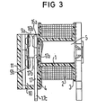
- Fig. 3 das Relais von Fig. 1 in einem Querschnitt.
- Das in den Fig. 1 bis 3 dargestellte Relais besitzt einen Spulenkörper 1 mit einer Wicklung 2, die zwischen den Flanschen 3 und 4 aufgebracht ist. Längs der Spulenachse ist im Spulenkörper 1 ein Eisenkern 5 angeordnet, der mit dem einen Ende 5a mit dem ersten Schenkel 6a eines winkelförmigen Joches 6 verbunden ist. Das andere Ende 5b des Kerns dient als Polfläche und bildet einen Arbeitsluftspalt mit einem Anker 7, der mit einem Fortsatz 7a in einer Ausnehmung 6c des zweiten Jochschenkels 6b liegt und an einer Lagerschneide 6d gelagert ist. Mittels einer Rückstellfeder in Gestalt einer Schraubenfeder 8 wird der Anker in seine Ruhestellung gezogen, während er beim Ansprechen des Relais entgegen der Kraft der Feder 8 an das Kernende 5b angezogen wird und dabei die auf ihm befestigte Brückenkontaktfeder 9 schaltet. Insoweit entspricht das Relais einem bekannten Aufbau.
- Die Kontaktanordnung ist in einer Kontakttasche 10 angeordnet, wobei diese Kontakttasche durch einen Ansatz 11 am Spulenkörperflansch 4 in einem Stück mit dem Spulenkörper geformt ist. In der Kontakttasche sind vier Aufnahmeschlitze 12, 13, 14 und 15 zur Aufnahme von Gegenkontaktelementen vorgesehen. Im dargestellten Ausführungsbeispiel sind lediglich die Aufnahmeschlitze 12 und 13 mit Gegenkontaktelementen 16 und 17 bestückt, während die gegenüberliegenden Aufnahmeschlitze 14 und 15 freibleiben. Damit ist das dargestellte Relais als Brückenschliesser ausgebildet, da die Ruheseite der Brückenkontaktfeder 9 nicht bestückt ist. Die nicht in allen Ausführungsformen benutzten Aufnahmeschlitze 14 und 15 sind zweckmässigerweise durch dünne Formtrennwände verschlossen, welche nur bedarfsweise bei Bestückung dieser Aufnahmeschlitze durch die eingesteckten Anschlussstachel der Gegenkontaktelemente durchstossen werden.
- Das kurze Gegenkontaktelement 17 trägt an seinem freien Ende 17a einen Kontaktniet 17b, während das längere Gegenkontaktelement 16 an seinem freien Ende einen Querschenkel 16a aufweist, welcher das freie Ende 17a des anderen Kontaktelementes überkragt und in dem Bereich oberhalb des zweiten Gegenkontaktelementes 17 einen Kontaktniet 16b trägt. Die beiden Gegenkontaktelemente 16 und 17 liegen somit gänzlich in einer Ebene, wobei ihre beiden Kontaktniete 16b und 17b den gleichen Abstand zur Schwenkachse der Brückenkontaktfeder 9 besitzen, so dass beim Anziehen des Ankers 7 beide Kontaktniete 16b und 17b gleichzeitig mit den Kontaktnieten 9a und 9b des Brückenkontaktstückes 9c in Berührung kommen und durch die torsionsfähige Kontaktfeder 9 mit dem gleichen Kontaktdruck beaufschlagt werden.
- Die Anschlussstachel 16c bzw. 17c der Gegenkontaktelemente 16 und 17 sind so ausgebildet, dass sie einen möglichst grossen Abstand zueinander aufweisen. Zur Erhöhung der Isolationsfestigkeit zwischen den Gegenkontaktelementen und zur Verbesserung der Steifigkeit des Trägers ist in der Kontakttasche eine Trennwand 18 vorgesehen. Wie bereits erwähnt, könnten auch die Aufnahmeschlitze 14 und 15 mit Gegenkontaktelementen 16 und 17 versehen werden, welche mit der Kontaktfeder 9 einen Ruhekontakt bilden würden, so dass das Relais insgesamt als Brückenumschalter ausgebildet wäre.
- Die Brückenkontaktfeder 9 braucht lediglich mit ihrem Brückenkontaktstück 9c am freien Ende den Schaltstrom zu führen, so dass sie auch isoliert am Anker 7 befestigt sein kann. Sie weist im Bereich zwischen dem Brückenkontaktstück 9c und ihrem Befestigungsende 9d einen durch Einschnitte im Querschnitt verminderten Steg 9e auf, dessen Breite geringer ist als der Abstand der Kontaktniete 9a und 9b. Dieser schmale Steg wirkt damit als Torsionssteg, über den unterschiedliche Kontakt- öffnungen des oberen und unteren Kontaktes ausgeglichen werden können, um gleiche Kontaktkräfte zu erhalten. Im Bereich zwischen dem Befestigungsende 9d und dem Steg 9e besitzt die Kontaktfeder einen trapezförmigen Abschnitt, wodurch die elastische Durchbiegung verbessert wird. In diesem trapezförmigen Abschnitt ist ausserdem ein Vorspannknick 9f vorgesehen, der die Kontaktkräfte erhöht und die Abbrandsicherheit verbessert.
- Zur Verhinderung von Überschlägen bei hohen Schaltspannungen ist die Kontaktfeder 9 im Bereich ihres Brückenkontaktstückes 9c an ihren Aussenkanten gerundet. Ausserdem besitzt sie an ihrem freien Ende noch einen vorstehenden Lappen 9g, welcher in der dargestellten Ausführungsform an einer Anschlagnase 19 anschlägt und dadurch die Ruhelage des Ankers festlegt. Bei einer Bestückung der Aufnahmeschlitze 14 und 15 mit Gegenkontaktelementen, also bei einer Öffner-oder Wechslerausführung des Relais, kann der Lappen 9g abgeschnitten werden.
Claims (6)
Applications Claiming Priority (2)
| Application Number | Priority Date | Filing Date | Title |
|---|---|---|---|
| DE8234360U | 1982-12-07 | ||
| DE8234360U DE8234360U1 (de) | 1982-12-07 | 1982-12-07 | Elektromagnetisches Relais |
Publications (2)
| Publication Number | Publication Date |
|---|---|
| EP0113440A1 EP0113440A1 (de) | 1984-07-18 |
| EP0113440B1 true EP0113440B1 (de) | 1986-06-04 |
Family
ID=6746280
Family Applications (1)
| Application Number | Title | Priority Date | Filing Date |
|---|---|---|---|
| EP83112209A Expired EP0113440B1 (de) | 1982-12-07 | 1983-12-05 | Elektromagnetisches Relais |
Country Status (4)
| Country | Link |
|---|---|
| US (1) | US4509028A (de) |
| EP (1) | EP0113440B1 (de) |
| JP (1) | JPS59111221A (de) |
| DE (2) | DE8234360U1 (de) |
Families Citing this family (6)
| Publication number | Priority date | Publication date | Assignee | Title |
|---|---|---|---|---|
| US4937544A (en) * | 1988-01-29 | 1990-06-26 | Siemens Aktiengesellschaft | "Contact arrangement for a relay" |
| DE9015406U1 (de) * | 1990-11-09 | 1992-03-05 | Siemens AG, 8000 München | Elektromagnetisches Relais mit auf dem Anker befestigter Kontaktfeder |
| DE19933797A1 (de) * | 1999-07-19 | 2001-03-08 | Tyco Electronics Logistics Ag | Relais mit Wippanker |
| GB0118327D0 (en) | 2001-07-27 | 2001-09-19 | Tyco Electronics Amp Gmbh | Relay |
| JP5222669B2 (ja) * | 2008-09-16 | 2013-06-26 | 富士通コンポーネント株式会社 | 電磁継電器 |
| CN103337415A (zh) * | 2013-06-14 | 2013-10-02 | 东莞市三友联众电器有限公司 | 一种继电器接触系统 |
Family Cites Families (10)
| Publication number | Priority date | Publication date | Assignee | Title |
|---|---|---|---|---|
| GB1200321A (en) * | 1967-01-16 | 1970-07-29 | Lucas Industries Ltd | Electromagnetic relays |
| US3555230A (en) * | 1968-11-12 | 1971-01-12 | American Mach & Foundry | Contact isolating means for multipoled switch devices |
| US4034323A (en) * | 1975-03-24 | 1977-07-05 | Oki Electric Industry Company, Ltd. | Magnetic relay |
| JPS5322734U (de) * | 1976-07-31 | 1978-02-25 | ||
| DE2638941C2 (de) * | 1976-08-28 | 1978-09-14 | Rudolf Schadow Gmbh, 1000 Berlin | Tastenaggregat mit nebeneinander angeordneten Schiebetastenschaltern |
| US4254391A (en) * | 1979-09-17 | 1981-03-03 | Fasco Industries, Inc. | Split armature relay |
| FR2486303A1 (fr) * | 1980-03-21 | 1982-01-08 | Bernier Et Cie Ets | Relais electromagnetique a armature pivotante a aimant permanent |
| DE3043447A1 (de) * | 1980-11-18 | 1982-07-01 | Rausch & Pausch, 8672 Selb | Relais mit einem gehaeuse oder einer abdeckkappe |
| DE8125818U1 (de) * | 1981-09-04 | 1982-10-14 | Siemens AG, 1000 Berlin und 8000 München | Elektromagnetisches Schaltrelais für hohe Strombelastung |
| DE3224468A1 (de) * | 1982-06-30 | 1984-01-05 | Siemens AG, 1000 Berlin und 8000 München | Relais mit brueckenkontaktfeder |
-
1982
- 1982-12-07 DE DE8234360U patent/DE8234360U1/de not_active Expired
-
1983
- 1983-10-28 US US06/546,450 patent/US4509028A/en not_active Expired - Fee Related
- 1983-11-28 JP JP58222275A patent/JPS59111221A/ja active Granted
- 1983-12-05 DE DE8383112209T patent/DE3363967D1/de not_active Expired
- 1983-12-05 EP EP83112209A patent/EP0113440B1/de not_active Expired
Also Published As
| Publication number | Publication date |
|---|---|
| EP0113440A1 (de) | 1984-07-18 |
| DE3363967D1 (en) | 1986-07-10 |
| JPS59111221A (ja) | 1984-06-27 |
| JPS6410899B2 (de) | 1989-02-22 |
| US4509028A (en) | 1985-04-02 |
| DE8234360U1 (de) | 1983-06-09 |
Similar Documents
| Publication | Publication Date | Title |
|---|---|---|
| EP0107611B1 (de) | Trennkontaktanordnung mit brückenartigen Kontaktlamellen für ausfahrbare Schaltgeräte | |
| EP0160121B1 (de) | Elektromagnet für elektrische Schaltgeräte, insbesondere Schütze | |
| EP0735628A2 (de) | Stromschiene mit Anschlussstift | |
| EP0281950B1 (de) | Elektromagnetisches Relais | |
| EP0033841B1 (de) | Relais | |
| DE3312754C1 (de) | Vorrichtung mit U-foermigen LSA-PLUS-Anschlusskontakten | |
| EP0211446A1 (de) | Elektromagnetisches Relais mit zwei Ankern | |
| DE3217528C2 (de) | Kontaktanordnung für Relais | |
| DE2825201C2 (de) | Kontaktvorrichtung | |
| EP0113440B1 (de) | Elektromagnetisches Relais | |
| EP0086316B1 (de) | Steckkontaktvorrichtung zur Herstellung einer elektrischen Verbindung zwischen zwei Schienen | |
| DE3232679C2 (de) | Elektromagnetisches Schaltrelais für hohe Strombelastung | |
| EP0081164B1 (de) | Elektromagnetisches Relais | |
| DE69603000T2 (de) | Elektrische Anschlussleiste | |
| DE2545180C3 (de) | Miniaturrelais | |
| EP0358286B1 (de) | Stromübertragende Gelenkanordnung für einen Kontakthebel | |
| EP0252344A1 (de) | Elektromagnetisches Relais | |
| EP3561830B1 (de) | Schaltkontaktanordnung | |
| DE2345638C2 (de) | ||
| DE3545356C2 (de) | Sicherheits-Schaltrelais | |
| DE2536706A1 (de) | Kontaktfedersatz fuer elektromagnetische relais | |
| DE1223913B (de) | Trennkontaktsatz fuer Trennloetoesenstreifen | |
| EP0833407A2 (de) | Reihenklemme mit Stromschiene | |
| DE3304301C2 (de) | Elektrischer Aufnahmekontakt | |
| DE2453980A1 (de) | Elektromagnetisches relais |
Legal Events
| Date | Code | Title | Description |
|---|---|---|---|
| PUAI | Public reference made under article 153(3) epc to a published international application that has entered the european phase |
Free format text: ORIGINAL CODE: 0009012 |
|
| AK | Designated contracting states |
Designated state(s): CH DE FR GB LI |
|
| 17P | Request for examination filed |
Effective date: 19841128 |
|
| GRAA | (expected) grant |
Free format text: ORIGINAL CODE: 0009210 |
|
| AK | Designated contracting states |
Kind code of ref document: B1 Designated state(s): CH DE FR GB LI |
|
| REF | Corresponds to: |
Ref document number: 3363967 Country of ref document: DE Date of ref document: 19860710 |
|
| ET | Fr: translation filed | ||
| PLBE | No opposition filed within time limit |
Free format text: ORIGINAL CODE: 0009261 |
|
| STAA | Information on the status of an ep patent application or granted ep patent |
Free format text: STATUS: NO OPPOSITION FILED WITHIN TIME LIMIT |
|
| 26N | No opposition filed | ||
| PGFP | Annual fee paid to national office [announced via postgrant information from national office to epo] |
Ref country code: CH Payment date: 19960320 Year of fee payment: 13 |
|
| PGFP | Annual fee paid to national office [announced via postgrant information from national office to epo] |
Ref country code: GB Payment date: 19961118 Year of fee payment: 14 |
|
| PG25 | Lapsed in a contracting state [announced via postgrant information from national office to epo] |
Ref country code: LI Effective date: 19961231 Ref country code: CH Effective date: 19961231 |
|
| REG | Reference to a national code |
Ref country code: CH Ref legal event code: PL |
|
| PG25 | Lapsed in a contracting state [announced via postgrant information from national office to epo] |
Ref country code: GB Free format text: LAPSE BECAUSE OF NON-PAYMENT OF DUE FEES Effective date: 19971205 |
|
| GBPC | Gb: european patent ceased through non-payment of renewal fee |
Effective date: 19971205 |
|
| PGFP | Annual fee paid to national office [announced via postgrant information from national office to epo] |
Ref country code: FR Payment date: 20011203 Year of fee payment: 19 |
|
| PGFP | Annual fee paid to national office [announced via postgrant information from national office to epo] |
Ref country code: DE Payment date: 20021230 Year of fee payment: 20 |
|
| PG25 | Lapsed in a contracting state [announced via postgrant information from national office to epo] |
Ref country code: FR Free format text: LAPSE BECAUSE OF NON-PAYMENT OF DUE FEES Effective date: 20030901 |
|
| REG | Reference to a national code |
Ref country code: FR Ref legal event code: ST |