EP0112242B1 - Dispositif de contrôle de la capacité d'une batterie d'éléments d'accumulateur - Google Patents
Dispositif de contrôle de la capacité d'une batterie d'éléments d'accumulateur Download PDFInfo
- Publication number
- EP0112242B1 EP0112242B1 EP83402361A EP83402361A EP0112242B1 EP 0112242 B1 EP0112242 B1 EP 0112242B1 EP 83402361 A EP83402361 A EP 83402361A EP 83402361 A EP83402361 A EP 83402361A EP 0112242 B1 EP0112242 B1 EP 0112242B1
- Authority
- EP
- European Patent Office
- Prior art keywords
- arrangement
- voltage
- comparator
- sequencing
- battery
- Prior art date
- Legal status (The legal status is an assumption and is not a legal conclusion. Google has not performed a legal analysis and makes no representation as to the accuracy of the status listed.)
- Expired
Links
- 238000012163 sequencing technique Methods 0.000 claims description 10
- 239000003112 inhibitor Substances 0.000 claims description 4
- 239000000725 suspension Substances 0.000 claims description 2
- 210000004027 cell Anatomy 0.000 claims 6
- 238000005286 illumination Methods 0.000 claims 1
- 210000000352 storage cell Anatomy 0.000 claims 1
- 238000005259 measurement Methods 0.000 description 8
- 238000004891 communication Methods 0.000 description 2
- 125000004122 cyclic group Chemical group 0.000 description 2
- 230000000694 effects Effects 0.000 description 2
- 238000000034 method Methods 0.000 description 2
- 230000004913 activation Effects 0.000 description 1
- 230000005540 biological transmission Effects 0.000 description 1
- 230000000903 blocking effect Effects 0.000 description 1
- 239000003990 capacitor Substances 0.000 description 1
- 238000007599 discharging Methods 0.000 description 1
- 230000005611 electricity Effects 0.000 description 1
- 230000005284 excitation Effects 0.000 description 1
- 230000002401 inhibitory effect Effects 0.000 description 1
- 238000002955 isolation Methods 0.000 description 1
- 238000012544 monitoring process Methods 0.000 description 1
- 230000001681 protective effect Effects 0.000 description 1
- 238000010200 validation analysis Methods 0.000 description 1
- 238000012795 verification Methods 0.000 description 1
Images
Classifications
-
- H—ELECTRICITY
- H01—ELECTRIC ELEMENTS
- H01M—PROCESSES OR MEANS, e.g. BATTERIES, FOR THE DIRECT CONVERSION OF CHEMICAL ENERGY INTO ELECTRICAL ENERGY
- H01M10/00—Secondary cells; Manufacture thereof
- H01M10/42—Methods or arrangements for servicing or maintenance of secondary cells or secondary half-cells
- H01M10/48—Accumulators combined with arrangements for measuring, testing or indicating the condition of cells, e.g. the level or density of the electrolyte
- H01M10/482—Accumulators combined with arrangements for measuring, testing or indicating the condition of cells, e.g. the level or density of the electrolyte for several batteries or cells simultaneously or sequentially
-
- G—PHYSICS
- G01—MEASURING; TESTING
- G01R—MEASURING ELECTRIC VARIABLES; MEASURING MAGNETIC VARIABLES
- G01R31/00—Arrangements for testing electric properties; Arrangements for locating electric faults; Arrangements for electrical testing characterised by what is being tested not provided for elsewhere
- G01R31/36—Arrangements for testing, measuring or monitoring the electrical condition of accumulators or electric batteries, e.g. capacity or state of charge [SoC]
- G01R31/382—Arrangements for monitoring battery or accumulator variables, e.g. SoC
- G01R31/3835—Arrangements for monitoring battery or accumulator variables, e.g. SoC involving only voltage measurements
-
- G—PHYSICS
- G01—MEASURING; TESTING
- G01R—MEASURING ELECTRIC VARIABLES; MEASURING MAGNETIC VARIABLES
- G01R31/00—Arrangements for testing electric properties; Arrangements for locating electric faults; Arrangements for electrical testing characterised by what is being tested not provided for elsewhere
- G01R31/36—Arrangements for testing, measuring or monitoring the electrical condition of accumulators or electric batteries, e.g. capacity or state of charge [SoC]
- G01R31/396—Acquisition or processing of data for testing or for monitoring individual cells or groups of cells within a battery
-
- Y—GENERAL TAGGING OF NEW TECHNOLOGICAL DEVELOPMENTS; GENERAL TAGGING OF CROSS-SECTIONAL TECHNOLOGIES SPANNING OVER SEVERAL SECTIONS OF THE IPC; TECHNICAL SUBJECTS COVERED BY FORMER USPC CROSS-REFERENCE ART COLLECTIONS [XRACs] AND DIGESTS
- Y02—TECHNOLOGIES OR APPLICATIONS FOR MITIGATION OR ADAPTATION AGAINST CLIMATE CHANGE
- Y02E—REDUCTION OF GREENHOUSE GAS [GHG] EMISSIONS, RELATED TO ENERGY GENERATION, TRANSMISSION OR DISTRIBUTION
- Y02E60/00—Enabling technologies; Technologies with a potential or indirect contribution to GHG emissions mitigation
- Y02E60/10—Energy storage using batteries
Definitions
- the present invention relates to a device for controlling the capacity of a battery of accumulator cells connected in series and discharged continuously, in particular for accumulator batteries installed in distribution stations.
- the regulations in force make it necessary to periodically check the capacity of these batteries. This verification is carried out by discharging the battery continuously by means of a rheostat mounted at the terminals of the battery, so as to adjust the discharge intensity to a constant value.
- each element of the battery is stopped, by disconnection thereof, as soon as its individual voltage is less than a given threshold.
- the discharge of the other elements is then continued, always keeping the intensity constant.
- the discharge time of the corresponding element is noted. This value being known as well as that of the discharge intensity, it is possible to determine the quantity of electricity restored by the battery element, that is to say the capacity thereof.
- the current procedure is however tedious and dangerous: it is first of all tedious because the operator must continuously measure, using a voltmeter, the voltage at the terminals of each of the elements of the battery, and this during the entire duration of the discharge.
- the duration of the discharge cycle is long (of the order of 5 to 10 hours), and the number of elements to be controlled individually is high (for example, the generally used batteries of 48 volts and 127 volts comprise respectively 24 and 58 elements).
- the procedure is also dangerous, insofar as the operator works continuously on a device having a dangerous voltage at its extreme terminals (48 or 127 volts) and must therefore take measurements with protective gloves.
- the object of the present invention is to get rid of this manual measurement, by making it possible to interrupt the discharge of the battery and to warn the operator as soon as one of the individual elements is discharged, that is to say ie when the voltage across its terminals falls below the predetermined threshold.
- the device of the invention makes it possible to indicate which of the elements is discharged, as well as the discharge time elapsed since the start of the measurement. The operator can then disconnect the element in question, note the corresponding discharge time, and give the device an order to resume the discharge operation, until the device detects the discharge of another individual element. .
- Such a multiplexed monitoring set of a set of batteries is already known per se (cf. for example US-A-3786343).
- the device may also include validation means making it possible to authorize the resumption of the operation of the sequencing means after suspension by the inhibiting means.
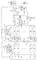
- the battery consists of a series of individual elements 10 arranged in series, the assembly being connected to a discharge rheostat 20 by means of a switch 21 (normally open at rest).
- An ampere meter 22 allows the discharge intensity to be adjusted to a constant value.
- the discharge time is around 5 hours at a constant intensity of 20 A.
- the sequencer circuit consists of a ring counter 30 supplied, on its input 31, with pulses coming from a clock circuit 80, delivering for example pulses every 24 milliseconds.
- the outputs 32 of the ring counter will be cyclically and successively activated.
- a control circuit 40 is provided, composed of a relay 41 controlled by a transistor 42.
- relays provide total galvanic isolation between the control circuits 40 and the measurement circuits 50: a circuit 50 is provided at the terminals 11, 12 of each of the elements 10; the contacts 51 and 52 of the relay 41, normally open in the absence of excitation of the relay, put the terminals of the element of communication into communication battery addressed by the sequencer circuit with an omnibus line 61 connected to the inverting input of a comparator circuit 60.
- the activation of the relay 41 also causes the lighting of a light-emitting diode 43 placed at the terminals of the relay 41: the lighting of this diode therefore indicates the element addressed by the sequencer circuit, on which is therefore performed the measurement.
- the voltage V M present on the bus line 61 is therefore a multiplexed voltage representative, successively, of the voltage at the terminals of each of the elements.
- the second input 62 of the comparator 60 is maintained at a constant reference voltage V REF representative of the threshold voltage corresponding to the discharge of an individual element (in our example, this voltage is 1.8 volts).
- This voltage is obtained from the supply voltage V by means of an integrated regulator 63 adjusted by an adjustable resistor 64.
- the capacitor 65 placed between the inverting input of the comparator and the ground acts in temporary memory to avoid sudden variations in the multiplexed voltage at each step of the sequencer circuit.
- comparator 60 controls, via a monostable 100, a circuit 70.
- This circuit first comprises a relay 71 which can on the one hand activate an alarm 72 to warn the operator, who can open the switch 21, thereby interrupting the discharge of the battery. Furthermore, the output of comparator 60 is connected to two NAND gates in cascade. The appearance of a signal at the output of the comparator has the effect of blocking the clock pulses from the circuit 80. The ring counter 30, which uses these pulses, therefore sees its operation interrupted. The relay 71 also suspends the operation of the stopwatch 90: the display 91 therefore indicates the time elapsed since the start of the discharge.
- each circuit 50 includes a switch 58, operable by the operator, to permanently set the corresponding output of the measurement circuit to a continuous positive voltage V, greater than the threshold voltage.
- the operation of the device is as follows: initially, all the elements 10 are connected in series and discharge in the rheostat 20, which the operator adjusts to obtain a constant discharge current.
- the relays 41 are actuated successively by the sequencer circuit and, as long as no element has its voltage lower than the threshold voltage, the comparator produces no signal at output: the gates 73, 74 remain on and the stopwatch 90 continues to operate.
- the output of the comparator is activated and blocks the transmission of the pulses from the clock 80, which suspends the operation of the sequencer 30. Furthermore, the relay 71 is activated, which triggers alarm 70 and suspends the operation of the stopwatch.
- the operator locates that of the diodes 57 which is on, indicating the element which caused the device to stop. It can then, after having temporarily disconnected the rheostat to suspend the discharge, disconnect this element, and, to restart the operation of the device, close the switch 58, thus continuously applying a higher voltage than the threshold voltage at l comparator input.
Landscapes
- Physics & Mathematics (AREA)
- General Physics & Mathematics (AREA)
- Engineering & Computer Science (AREA)
- Manufacturing & Machinery (AREA)
- Chemical & Material Sciences (AREA)
- Chemical Kinetics & Catalysis (AREA)
- Electrochemistry (AREA)
- General Chemical & Material Sciences (AREA)
- Secondary Cells (AREA)
- Tests Of Electric Status Of Batteries (AREA)
- Charge And Discharge Circuits For Batteries Or The Like (AREA)
- Measurement Of Current Or Voltage (AREA)
Applications Claiming Priority (2)
| Application Number | Priority Date | Filing Date | Title |
|---|---|---|---|
| FR8220859 | 1982-12-13 | ||
| FR8220859A FR2537785A1 (fr) | 1982-12-13 | 1982-12-13 | Dispositif de controle de la capacite d'une batterie d'elements d'accumulateur |
Publications (2)
| Publication Number | Publication Date |
|---|---|
| EP0112242A1 EP0112242A1 (fr) | 1984-06-27 |
| EP0112242B1 true EP0112242B1 (fr) | 1986-08-27 |
Family
ID=9280034
Family Applications (1)
| Application Number | Title | Priority Date | Filing Date |
|---|---|---|---|
| EP83402361A Expired EP0112242B1 (fr) | 1982-12-13 | 1983-12-06 | Dispositif de contrôle de la capacité d'une batterie d'éléments d'accumulateur |
Country Status (6)
| Country | Link |
|---|---|
| US (1) | US4590430A (cg-RX-API-DMAC10.html) |
| EP (1) | EP0112242B1 (cg-RX-API-DMAC10.html) |
| JP (1) | JPS59132379A (cg-RX-API-DMAC10.html) |
| CA (1) | CA1226900A (cg-RX-API-DMAC10.html) |
| DE (1) | DE3365726D1 (cg-RX-API-DMAC10.html) |
| FR (1) | FR2537785A1 (cg-RX-API-DMAC10.html) |
Families Citing this family (37)
| Publication number | Priority date | Publication date | Assignee | Title |
|---|---|---|---|---|
| JPS59135548A (ja) * | 1983-01-22 | 1984-08-03 | Toshiba Corp | 演算装置 |
| US4719428A (en) * | 1985-06-04 | 1988-01-12 | Tif Instruments, Inc. | Storage battery condition tester utilizing low load current |
| JPS634570A (ja) * | 1986-06-25 | 1988-01-09 | Hitachi Ltd | ナトリウム−硫黄電池の異常診断方法 |
| DE3702591A1 (de) * | 1987-01-29 | 1988-08-11 | Sonnenschein Accumulatoren | Schaltung zur laufenden ueberpruefung der qualitaet einer mehrzelligen batterie |
| IT1219776B (it) * | 1988-03-02 | 1990-05-24 | Beghelli G P B Srl | Sistema di controllo e diagnosi dello stato di carcia delle batterie specialmente per gruppi "di continuita'" di alimentazione elettrica |
| DE3940929C1 (cg-RX-API-DMAC10.html) * | 1989-12-12 | 1991-05-08 | Fraunhofer-Gesellschaft Zur Foerderung Der Angewandten Forschung Ev, 8000 Muenchen, De | |
| US5099211A (en) * | 1990-03-26 | 1992-03-24 | Nowak Dieter K | Battery voltage measurement system |
| US5153496A (en) * | 1990-09-27 | 1992-10-06 | Baxtrer International Inc. | Cell monitor and control unit for multicell battery |
| JPH04101246U (ja) * | 1991-02-13 | 1992-09-01 | セイコー電子工業株式会社 | 充電器 |
| DE4132229C2 (de) * | 1991-09-27 | 1994-02-24 | Mentzer Electronic Gmbh | Mikrocontroller-gesteuerte Einrichtung zur Analyse des Ladezustands einer mehrzeiligen Batterie |
| US5281920A (en) * | 1992-08-21 | 1994-01-25 | Btech, Inc. | On-line battery impedance measurement |
| FR2702885B1 (fr) * | 1993-03-15 | 1995-04-21 | Alcatel Converters | Système de contrôle de vieillissement d'une batterie et procédé mis en Óoeuvre dans un tel système. |
| FR2709832B1 (fr) * | 1993-09-09 | 1995-11-17 | Renault | Dispositif de contrôle de la décharge d'une pluralité de batteries montées en série. |
| DE4338178C2 (de) * | 1993-11-09 | 2003-04-30 | Aeg Energietechnik Gmbh | Anordnung zur Überwachung des Zustands von Brennstoffzellen-Modulen |
| FR2713781B1 (fr) * | 1993-12-09 | 1996-01-19 | Accumulateurs Fixes | Circuit de mesure pour ensemble modulaire de cellules électriquement montées en série, notamment pour batterie d'accumulateur électrique. |
| FR2719126B1 (fr) * | 1994-04-21 | 1996-05-24 | Accumulateurs Fixes | Circuit de mesure pour ensemble modulaire de cellules électriques raccordées en série, notamment pour ensemble de type batterie d'accumulateur. |
| US5646534A (en) * | 1995-01-06 | 1997-07-08 | Chrysler Corporation | Battery monitor for electric vehicles |
| JPH08233916A (ja) * | 1995-02-28 | 1996-09-13 | Sanyo Electric Co Ltd | 電池検査方法 |
| DE19518729C2 (de) * | 1995-05-22 | 1997-06-12 | Mentzer Electronic Gmbh | Einrichtung zum Messen von Teilspannungen |
| US5705929A (en) * | 1995-05-23 | 1998-01-06 | Fibercorp. Inc. | Battery capacity monitoring system |
| US5712568A (en) * | 1995-09-05 | 1998-01-27 | Ford Motor Company | Battery voltage measurement system |
| GB2321315A (en) * | 1997-01-21 | 1998-07-22 | Silviu Puchianu | Estimating total working capacity of a battery |
| US6133709A (en) * | 1997-01-21 | 2000-10-17 | Metrixx Limited | Signalling system |
| WO1999045402A1 (en) * | 1998-03-06 | 1999-09-10 | Matsushita Electric Industrial Co., Ltd. | Voltage measuring instrument with flying capacitor |
| US7505856B2 (en) * | 1999-04-08 | 2009-03-17 | Midtronics, Inc. | Battery test module |
| SE9904403D0 (sv) * | 1999-12-03 | 1999-12-03 | Ericsson Telefon Ab L M | Capacity testing method and arrangement |
| JP4472820B2 (ja) * | 2000-01-18 | 2010-06-02 | パナソニック株式会社 | 電池の電圧検出装置および検出方法 |
| JP4210030B2 (ja) * | 2000-11-02 | 2009-01-14 | パナソニック株式会社 | 積層電圧計測装置 |
| JP4092904B2 (ja) * | 2001-11-09 | 2008-05-28 | トヨタ自動車株式会社 | 組電池の状態判定装置 |
| DE60332182D1 (de) * | 2002-01-31 | 2010-06-02 | Saft Groupe Sa | Entladungssteuerungsverfahren für eine Batterie |
| JP4179205B2 (ja) * | 2004-03-29 | 2008-11-12 | サンケン電気株式会社 | 電圧測定装置 |
| US7825627B2 (en) * | 2006-07-17 | 2010-11-02 | O2Micro International Limited | Monitoring battery cell voltage |
| TW200845461A (en) * | 2007-05-04 | 2008-11-16 | Iwei Technology Co Ltd | Recharging apparatus with battery capacity analyzing function |
| US9285429B2 (en) | 2011-02-21 | 2016-03-15 | Telefonaktiebolaget L M Ericsson (Publ) | Arrangement and method for determining the state of a battery based on a capacity of the battery |
| CN102275524A (zh) * | 2011-06-30 | 2011-12-14 | 奇瑞汽车股份有限公司 | 一种动力电池包的诊断系统及其诊断方法 |
| DE102014219582A1 (de) * | 2014-09-26 | 2016-03-31 | Younicos Ag | Verfahren zum Vermessen oder Prüfen der Leistungsfähigkeit von Akkumulatoren |
| DE102017208770B4 (de) * | 2017-05-23 | 2019-03-28 | Audi Ag | Verfahren zur Prüfung eines Batteriezustands und Prüfvorrichtung zur Prüfung eines Batteriezustands |
Family Cites Families (12)
| Publication number | Priority date | Publication date | Assignee | Title |
|---|---|---|---|---|
| US2621231A (en) * | 1948-06-22 | 1952-12-09 | Fox Prod Co | Apparatus for testing batteries |
| US3487295A (en) * | 1968-01-08 | 1969-12-30 | Westinghouse Electric Corp | Static battery monitor and voltage reference level switch therefor |
| US3586962A (en) * | 1969-02-28 | 1971-06-22 | Edward C Rebstock | Battery cell monitoring apparatus |
| US3786343A (en) * | 1973-03-19 | 1974-01-15 | Us Navy | Battery monitor system |
| AT331357B (de) * | 1974-01-11 | 1976-08-25 | Jungfer Akkumulatoren | Elektrische anzeigevorrichtung fur den ladezustand einer sekundarbatterie |
| US3942104A (en) * | 1974-05-03 | 1976-03-02 | Engelhard Minerals & Chemicals Corporation | Cell balance detector for electrolytic cell assemblies |
| FR2315776A1 (fr) * | 1975-06-24 | 1977-01-21 | Europ Accumulateurs | Procede et dispositif de controle d'une batterie d'accumulateurs |
| DE2842817B1 (de) * | 1978-09-30 | 1979-05-17 | Siemens Ag | Ermittlung des Ladezustandes einer Batterie |
| US4352067A (en) * | 1980-06-02 | 1982-09-28 | Dc Electronic Industries, Inc. | Battery analyzer |
| US4280097A (en) * | 1980-07-14 | 1981-07-21 | The United States Of America As Represented By The Secretary Of The Navy | Isolated DC voltage monitoring system |
| GB2086060B (en) * | 1980-10-11 | 1984-06-13 | Lucas Industries Ltd | Battery monitoring system |
| US4484140A (en) * | 1982-04-23 | 1984-11-20 | The United States Of America As Represented By The Secretary Of The Navy | Battery scanning system |
-
1982
- 1982-12-13 FR FR8220859A patent/FR2537785A1/fr active Granted
-
1983
- 1983-12-06 EP EP83402361A patent/EP0112242B1/fr not_active Expired
- 1983-12-06 DE DE8383402361T patent/DE3365726D1/de not_active Expired
- 1983-12-07 US US06/558,792 patent/US4590430A/en not_active Expired - Lifetime
- 1983-12-13 JP JP58233775A patent/JPS59132379A/ja active Pending
- 1983-12-13 CA CA000443137A patent/CA1226900A/en not_active Expired
Also Published As
| Publication number | Publication date |
|---|---|
| JPS59132379A (ja) | 1984-07-30 |
| FR2537785A1 (fr) | 1984-06-15 |
| DE3365726D1 (en) | 1986-10-02 |
| US4590430A (en) | 1986-05-20 |
| FR2537785B1 (cg-RX-API-DMAC10.html) | 1985-05-03 |
| EP0112242A1 (fr) | 1984-06-27 |
| CA1226900A (en) | 1987-09-15 |
Similar Documents
| Publication | Publication Date | Title |
|---|---|---|
| EP0112242B1 (fr) | Dispositif de contrôle de la capacité d'une batterie d'éléments d'accumulateur | |
| EP0110775B1 (fr) | Régulateur à faible tension de déchet | |
| FR2702885A1 (fr) | Système de contrôle de vieillissement d'une batterie et procédé mis en Óoeuvre dans un tel système. | |
| EP0027425B1 (fr) | Procédé et dispositif pour éviter les fraudes sur le prix indiqué par l'afficheur lumineux d'un taximètre électronique et taximètre équipé d'un tel dispositif | |
| EP0190961A1 (fr) | Alimentation en courant continu à point de fonctionnement ajustable | |
| CA2280598A1 (fr) | Dispositif electronique portable avec circuit de controle de la decharge d'une batterie, et procede associe | |
| EP3371544B1 (fr) | Procédé de mise a feu d'un détonateur électronique et détonateur electronique | |
| FR2873209A1 (fr) | Procede et dispositif pour la determination de parametres de fonctionnement d'une batterie | |
| EP2165246A2 (fr) | Procede et systeme de gestion de coupures d'alimentation electrique a bord d'un aeronef | |
| EP0077531A1 (fr) | Dispositif de charge d'un ensemble de batteries, notamment de batteries tampons alimentées par une source d'énergie de puissance limitée | |
| EP0536058B2 (fr) | Déclencheur électronique comportant des moyens de signalisation locale du type de défaut détecté | |
| FR2689677A1 (fr) | Dispositif de contrôle de l'état d'un fusible multibrins. | |
| EP0171629B1 (fr) | Dispositif de test d'autonomie pour bloc d'éclairage de sécurité | |
| FR2458295A1 (fr) | Circuit de controle du dispositif d'allumage d'une installation d'extinction rapide d'incendie | |
| GB2074403A (en) | Emergency light fitting with battery discharge and test facility | |
| FR2719947A1 (fr) | Procédé et dispositif d'entretien d'un accumulateur utilisé en marche flottante, notamment pour un appareil de sécurité. | |
| FR2721125A1 (fr) | Procédé et dispositif antivol pour équipements électroniques spécifiques d'un taxi. | |
| FR2957469A1 (fr) | Systeme de memorisation d’une panne dans un circuit de puissance | |
| EP0247398B1 (fr) | Commande électronique d'installation de graissage centralisée, en particulier pour vehicules | |
| EP1022575B1 (fr) | Dispositif de mesure de la consommation électrique d'un terminal portable de traitement de données ou de signaux | |
| FR2477282A1 (fr) | Dispositif de controle de la capacite de batteries d'accumulateurs | |
| EP0364371A1 (fr) | Dispositif de contrôle et de charge d'une batterie d'accumulateurs notamment | |
| FR2609555A1 (fr) | Procede et dispositif de mesure du temps d'autonomie disponible sur une batterie d'accumulateurs electriques | |
| CH636735A5 (fr) | Procede de regulation du circuit de charge d'un chargeur de batterie, et circuit electronique pour la mise en oeuvre de ce procede. | |
| FR2545780A1 (fr) | Pompe de cale et circuit de minuterie pour une telle pompe |
Legal Events
| Date | Code | Title | Description |
|---|---|---|---|
| PUAI | Public reference made under article 153(3) epc to a published international application that has entered the european phase |
Free format text: ORIGINAL CODE: 0009012 |
|
| AK | Designated contracting states |
Designated state(s): BE DE GB IT |
|
| 17P | Request for examination filed |
Effective date: 19840618 |
|
| GRAA | (expected) grant |
Free format text: ORIGINAL CODE: 0009210 |
|
| AK | Designated contracting states |
Kind code of ref document: B1 Designated state(s): BE DE GB IT |
|
| ITF | It: translation for a ep patent filed | ||
| REF | Corresponds to: |
Ref document number: 3365726 Country of ref document: DE Date of ref document: 19861002 |
|
| PLBE | No opposition filed within time limit |
Free format text: ORIGINAL CODE: 0009261 |
|
| STAA | Information on the status of an ep patent application or granted ep patent |
Free format text: STATUS: NO OPPOSITION FILED WITHIN TIME LIMIT |
|
| 26N | No opposition filed | ||
| ITTA | It: last paid annual fee | ||
| REG | Reference to a national code |
Ref country code: GB Ref legal event code: IF02 |
|
| PGFP | Annual fee paid to national office [announced via postgrant information from national office to epo] |
Ref country code: GB Payment date: 20021129 Year of fee payment: 20 |
|
| PGFP | Annual fee paid to national office [announced via postgrant information from national office to epo] |
Ref country code: DE Payment date: 20021211 Year of fee payment: 20 |
|
| PGFP | Annual fee paid to national office [announced via postgrant information from national office to epo] |
Ref country code: BE Payment date: 20030102 Year of fee payment: 20 |
|
| PG25 | Lapsed in a contracting state [announced via postgrant information from national office to epo] |
Ref country code: GB Free format text: LAPSE BECAUSE OF EXPIRATION OF PROTECTION Effective date: 20031205 |
|
| BE20 | Be: patent expired |
Owner name: *ELECTRICITE DE FRANCE SERVICE NATIONAL Effective date: 20031206 |
|
| REG | Reference to a national code |
Ref country code: GB Ref legal event code: PE20 |