EP0111665A1 - Automatische Referenzeinstellung für ein Positionsfehlersignal bei einem Servosystem für Platten - Google Patents
Automatische Referenzeinstellung für ein Positionsfehlersignal bei einem Servosystem für Platten Download PDFInfo
- Publication number
- EP0111665A1 EP0111665A1 EP83110301A EP83110301A EP0111665A1 EP 0111665 A1 EP0111665 A1 EP 0111665A1 EP 83110301 A EP83110301 A EP 83110301A EP 83110301 A EP83110301 A EP 83110301A EP 0111665 A1 EP0111665 A1 EP 0111665A1
- Authority
- EP
- European Patent Office
- Prior art keywords
- signal
- pes
- servo
- signals
- gain
- Prior art date
- Legal status (The legal status is an assumption and is not a legal conclusion. Google has not performed a legal analysis and makes no representation as to the accuracy of the status listed.)
- Granted
Links
Images


Classifications
-
- G—PHYSICS
- G11—INFORMATION STORAGE
- G11B—INFORMATION STORAGE BASED ON RELATIVE MOVEMENT BETWEEN RECORD CARRIER AND TRANSDUCER
- G11B5/00—Recording by magnetisation or demagnetisation of a record carrier; Reproducing by magnetic means; Record carriers therefor
- G11B5/48—Disposition or mounting of heads or head supports relative to record carriers ; arrangements of heads, e.g. for scanning the record carrier to increase the relative speed
- G11B5/54—Disposition or mounting of heads or head supports relative to record carriers ; arrangements of heads, e.g. for scanning the record carrier to increase the relative speed with provision for moving the head into or out of its operative position or across tracks
- G11B5/55—Track change, selection or acquisition by displacement of the head
- G11B5/5521—Track change, selection or acquisition by displacement of the head across disk tracks
- G11B5/5526—Control therefor; circuits, track configurations or relative disposition of servo-information transducers and servo-information tracks for control thereof
- G11B5/553—Details
- G11B5/5547—"Seek" control and circuits therefor
-
- G—PHYSICS
- G11—INFORMATION STORAGE
- G11B—INFORMATION STORAGE BASED ON RELATIVE MOVEMENT BETWEEN RECORD CARRIER AND TRANSDUCER
- G11B5/00—Recording by magnetisation or demagnetisation of a record carrier; Reproducing by magnetic means; Record carriers therefor
- G11B5/48—Disposition or mounting of heads or head supports relative to record carriers ; arrangements of heads, e.g. for scanning the record carrier to increase the relative speed
- G11B5/58—Disposition or mounting of heads or head supports relative to record carriers ; arrangements of heads, e.g. for scanning the record carrier to increase the relative speed with provision for moving the head for the purpose of maintaining alignment of the head relative to the record carrier during transducing operation, e.g. to compensate for surface irregularities of the latter or for track following
- G11B5/596—Disposition or mounting of heads or head supports relative to record carriers ; arrangements of heads, e.g. for scanning the record carrier to increase the relative speed with provision for moving the head for the purpose of maintaining alignment of the head relative to the record carrier during transducing operation, e.g. to compensate for surface irregularities of the latter or for track following for track following on disks
- G11B5/59605—Circuits
- G11B5/59622—Gain control; Filters
Definitions
- This invention relates to circuitry for use with track-seeking and track-following servo systems for magnetic disk files.
- a number of current magnetic disk files employ servo systems which are operable to move one or more magnetic heads from one concentric recording track to another track on a disk surface (track-seeking), and then to maintain the head or heads accurately positioned over the selected track for data operations (track-following).
- Such files employ some sort of recorded servo information which is read to provide signals which control the movement of the head or heads.
- Such recorded servo information may be in the form of sectors of servo information interspersed around the disk with data information, the sectors of servo information being read and used for track-following control during the following data information portion.
- disk files employ a separate disk surface dedicated to servo information and containing some type of recorded servo pattern which is read by a servo head to be used in generating the signals for providing the desired track-seeking and track-following control information.
- One such servo pattern employed is the so-called "quad burst" pattern as described in the IBM Technical Disclosure Bulletin, Vol. 21, No. 2, July 1978, pp804-5, entitled “Quad-Burst PES System for Disk File Servo" by Herrington and Mueller, which is incorporated herein by reference.
- This servo pattern has a primary component P and a quadrature component Q in quadrature with P, and from these components four position error signals (PES) signals can be generated, PES P, PES Q, PES P and PES Q for use in controlling the servo system.
- PES position error signals
- circuitry which will perform the above-described calibration at the time of manufacture and every time the disk file is powered on in the field.
- FIG. 1 shows the servo circuitry used in connection with the quad burst servo pattern, as well as the prior art calibration resistor. required.
- the circuitry includes a variable gain amplifier 11 which receives the low level servo signal from the servo head and, after amplification, supplies it through a filter amplifier 12 to multipliers 13, 14, and 15.
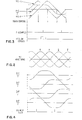
- the outputs of multipliers 13 and 14 are supplied through filter amplifiers 16 and 17, respectively, to produce the four output signals PES P, PES Q, PES P and PES Q whose waveforms and relationships are shown in FIG. 2, and will.be described below.
- the output of multiplier 15 is an AGC sense signal and is compared in an operational amplifier 18 with a reference signal supplied on a terminal 19 to produce an output from amplifier 18 which is supplied as an AGC signal to control the gain of amplifier 11.
- the calibration resistor required by this prior art system is identified at 21 and is selected after the above-described calibration test to properly balance the AGC sense signal from multiplier 15 with the reference voltage on terminal 19.
- the PES waveforms generated from the quad burst servo pattern are very linear with respect to position, except near the peaks.
- the "PES P plus PES Q” signal has a uniformly flat top portion that accurately represents the magnitude of the linear portion of PES P and PES Q.
- the level of "P plus Q” at "P equals Q” can then be compared to a precision reference voltage to determine whether the amplitude needs to be increased or decreased.
- the “sample” and “error” waveforms are shown in FIG. 3.
- the comparator outputs can then be "dotted" together so that if any one of the four amplitude signals is more positive than the reference, the output will be logically zero, causing a counter to decrease by one when "cylinder pulse” occurs, and thereby reducing the reference voltage to the AGC loop. Otherwise the counter will increase by one to increase the reference voltage.
- the calibration of PES amplitude can be performed during "rezero". This is a warm-up routine during which the surface is scanned at low velocity, producing a sufficiently long train of PES cycles to allow the gain correction function to be performed.
- the hardware required to build this control function consists of four comparators 26, 27, 28 and 29, an up/down counter 31, a digital-to-analog converter (DAC) 32, Operational Amplifier 18 (from FIG. 1), and several resistors and capacitors.
- the gain control voltage generated by this system is only a portion of the overall gain reference voltage, since the range need only be sufficient to compensate for the mismatch between the PES waveforms and the AGC sense level.
- the up/down counter 31 can be set to any value when power is initially applied. Then, near the end of the warm-up period, the gain correction circuitry would be enabled during a constant, low velocity scan of the surface (rezero). The counter would count once for each track crossing. With an eight-bit counter initially set to zero, it would then take only 256 tracks to reach its maximum count. If desired, the gain could also be recalibrated at times other than warm-up.
- This invention can also be applied to the general case of any pair of signals generated in quadrature where the amplitude must be either sensed or controlled. It can apply to either triangular or sinusoidal waveforms.
Applications Claiming Priority (2)
| Application Number | Priority Date | Filing Date | Title |
|---|---|---|---|
| US451583 | 1982-12-20 | ||
| US06/451,583 US4551776A (en) | 1982-12-20 | 1982-12-20 | Automatic reference adjustment for position error signal on disk file servo system |
Publications (2)
| Publication Number | Publication Date |
|---|---|
| EP0111665A1 true EP0111665A1 (de) | 1984-06-27 |
| EP0111665B1 EP0111665B1 (de) | 1987-01-14 |
Family
ID=23792814
Family Applications (1)
| Application Number | Title | Priority Date | Filing Date |
|---|---|---|---|
| EP83110301A Expired EP0111665B1 (de) | 1982-12-20 | 1983-10-17 | Automatische Referenzeinstellung für ein Positionsfehlersignal bei einem Servosystem für Platten |
Country Status (4)
| Country | Link |
|---|---|
| US (1) | US4551776A (de) |
| EP (1) | EP0111665B1 (de) |
| JP (1) | JPS59117758A (de) |
| DE (1) | DE3369223D1 (de) |
Cited By (3)
| Publication number | Priority date | Publication date | Assignee | Title |
|---|---|---|---|---|
| EP0202480A2 (de) * | 1985-05-24 | 1986-11-26 | International Business Machines Corporation | Positionierung von Köpfen auf Platten ohne Fehler |
| EP0272076A2 (de) * | 1986-12-16 | 1988-06-22 | Fujitsu Limited | Antriebssystem für Magnetplatten |
| EP0572789A2 (de) * | 1992-06-04 | 1993-12-08 | Hewlett-Packard Company | Stossdämpfersystem und -verfahren in einer Schreib-/Leseplattenvorrichtung |
Families Citing this family (19)
| Publication number | Priority date | Publication date | Assignee | Title |
|---|---|---|---|---|
| EP0247829A1 (de) * | 1986-05-26 | 1987-12-02 | Pioneer Electronic Corporation | Verfahren und Vorrichtung zur Korrektur der Schleifenverstärkung einer feineinstellbaren Servoschleife |
| US4688118A (en) * | 1986-07-01 | 1987-08-18 | Hewlett-Packard Company | Servo gain compensation in a disc drive |
| US4823212A (en) * | 1986-11-26 | 1989-04-18 | Hewlett-Packard Company | Sampled servo code format and system for a disc drive |
| US4989103A (en) * | 1987-03-03 | 1991-01-29 | Unisys Corp. | Adjustment of position slope for disk drive servo using half-track point |
| US5241431A (en) * | 1987-03-03 | 1993-08-31 | Unisys Corporation | Apparatus for adjustment of position slope for servo |
| US4797756A (en) * | 1987-03-05 | 1989-01-10 | Unisys Corp. | Method for positioning head in disk drive deriving "position" offset from "quadrature" signals |
| US5034746A (en) * | 1988-09-21 | 1991-07-23 | International Business Machines Corporation | Analog-to-digital converter for computer disk file servo position error signal |
| US5189571A (en) * | 1990-04-30 | 1993-02-23 | Seagate Technology, Inc. | Adaptive settle time minimization for a hard disk drive |
| US5329409A (en) * | 1991-07-24 | 1994-07-12 | Seagate Technology, Inc. | Correction of current feedback offset for disc drive servo systems |
| JP2608220B2 (ja) * | 1992-01-31 | 1997-05-07 | 富士通株式会社 | 磁気ディスク装置のポジション感度調整方法 |
| US5691617A (en) * | 1993-07-12 | 1997-11-25 | Seagate Technology, Inc. | Disc drive transducer deadbeat settle method utilizing interval correction |
| US5602692A (en) * | 1994-10-07 | 1997-02-11 | International Business Machines Corporation | Sampled position error signal demodulation system for banded data disk drives |
| US5717538A (en) * | 1995-01-20 | 1998-02-10 | International Business Machines Corporation | Asynchronous position error signal detector employing weighted accumulation for use in servo system |
| JP3292621B2 (ja) * | 1995-04-20 | 2002-06-17 | 富士通株式会社 | ディスク装置のポジション感度調整装置及び方法 |
| JPH09128916A (ja) | 1995-10-31 | 1997-05-16 | Fujitsu Ltd | ディスク装置 |
| US6067204A (en) * | 1996-06-03 | 2000-05-23 | Seagate Technology, Inc. | Disc drive servo pattern insensitive to read head |
| US5774299A (en) * | 1996-08-13 | 1998-06-30 | Seagate Technology, Inc. | Adaptive calibration of read/write elements in a disc drive |
| US6078445A (en) * | 1997-08-07 | 2000-06-20 | International Business Machines Corporation | Gain control for a dual burst, dual frequency PES servo pattern |
| WO1999031956A2 (en) * | 1997-12-19 | 1999-07-01 | Lsi Logic Corporation | Automated servo gain adjustment using fourier transform |
Citations (5)
| Publication number | Priority date | Publication date | Assignee | Title |
|---|---|---|---|---|
| US3881184A (en) * | 1974-05-28 | 1975-04-29 | Ibm | Adaptive digital servo system |
| DE2616806A1 (de) * | 1975-04-28 | 1976-11-11 | Burroughs Corp | Einrichtung zum positionieren eines lese/schreibkopfes relativ zu einem ebenen, bewegten traeger, insbesondere einer magnetspeicherplatte |
| DE2755652A1 (de) * | 1976-12-22 | 1978-06-29 | Ibm | Verfahren zur steuerung der spurverfolgung eines schreib/lesekopfes in einem datenspeicher |
| DE2837623A1 (de) * | 1977-11-14 | 1979-05-17 | Ibm | Einrichtung zur servoregelung der spurfolge des magnetkopfes eines magnetplattenspeichers |
| DE3019261A1 (de) * | 1979-06-15 | 1980-12-18 | Magnetic Peripherals Inc | Schaltung zur steuerung des wandlers einer regelschaltung fuer den magnetkopf eines plattenspeichers |
Family Cites Families (5)
| Publication number | Priority date | Publication date | Assignee | Title |
|---|---|---|---|---|
| US3818502A (en) * | 1972-09-05 | 1974-06-18 | Ibm | Automatic head width correction |
| US4415939A (en) * | 1981-04-27 | 1983-11-15 | Iomega Corporation | Head positioning servo for disk drive |
| US4400747A (en) * | 1981-06-26 | 1983-08-23 | International Business Machines Corporation | Servo system for data storage apparatus |
| US4451859A (en) * | 1982-04-02 | 1984-05-29 | Ampex Corporation | Magnetic video head position control |
| US4480217A (en) * | 1982-12-14 | 1984-10-30 | Storage Technology Corporation | Automatic velocity calibrator for a velocity servo loop in a magnetic disk drive |
-
1982
- 1982-12-20 US US06/451,583 patent/US4551776A/en not_active Expired - Fee Related
-
1983
- 1983-10-17 EP EP83110301A patent/EP0111665B1/de not_active Expired
- 1983-10-17 DE DE8383110301T patent/DE3369223D1/de not_active Expired
- 1983-11-14 JP JP58212606A patent/JPS59117758A/ja active Granted
Patent Citations (5)
| Publication number | Priority date | Publication date | Assignee | Title |
|---|---|---|---|---|
| US3881184A (en) * | 1974-05-28 | 1975-04-29 | Ibm | Adaptive digital servo system |
| DE2616806A1 (de) * | 1975-04-28 | 1976-11-11 | Burroughs Corp | Einrichtung zum positionieren eines lese/schreibkopfes relativ zu einem ebenen, bewegten traeger, insbesondere einer magnetspeicherplatte |
| DE2755652A1 (de) * | 1976-12-22 | 1978-06-29 | Ibm | Verfahren zur steuerung der spurverfolgung eines schreib/lesekopfes in einem datenspeicher |
| DE2837623A1 (de) * | 1977-11-14 | 1979-05-17 | Ibm | Einrichtung zur servoregelung der spurfolge des magnetkopfes eines magnetplattenspeichers |
| DE3019261A1 (de) * | 1979-06-15 | 1980-12-18 | Magnetic Peripherals Inc | Schaltung zur steuerung des wandlers einer regelschaltung fuer den magnetkopf eines plattenspeichers |
Cited By (6)
| Publication number | Priority date | Publication date | Assignee | Title |
|---|---|---|---|---|
| EP0202480A2 (de) * | 1985-05-24 | 1986-11-26 | International Business Machines Corporation | Positionierung von Köpfen auf Platten ohne Fehler |
| EP0202480A3 (en) * | 1985-05-24 | 1989-04-26 | International Business Machines Corporation | Positioning misaligned disk heads positioning misaligned disk heads |
| EP0272076A2 (de) * | 1986-12-16 | 1988-06-22 | Fujitsu Limited | Antriebssystem für Magnetplatten |
| EP0272076A3 (en) * | 1986-12-16 | 1990-03-14 | Fujitsu Limited | Magnetic disc drive system |
| EP0572789A2 (de) * | 1992-06-04 | 1993-12-08 | Hewlett-Packard Company | Stossdämpfersystem und -verfahren in einer Schreib-/Leseplattenvorrichtung |
| EP0572789A3 (de) * | 1992-06-04 | 1994-02-16 | Hewlett Packard Co |
Also Published As
| Publication number | Publication date |
|---|---|
| JPS59117758A (ja) | 1984-07-07 |
| JPH0150031B2 (de) | 1989-10-26 |
| DE3369223D1 (en) | 1987-02-19 |
| EP0111665B1 (de) | 1987-01-14 |
| US4551776A (en) | 1985-11-05 |
Similar Documents
| Publication | Publication Date | Title |
|---|---|---|
| EP0111665B1 (de) | Automatische Referenzeinstellung für ein Positionsfehlersignal bei einem Servosystem für Platten | |
| CA1279930C (en) | Method and apparatus for an improved sampled servo seek and track follow disc drive | |
| EP0000261B1 (de) | Schaltung zur direkten und rückgekoppelten Steuerung einer Positioniereinrichtung | |
| EP0003070B1 (de) | Zeitoptimale digitale Steuerung zum Positionieren unter Verwendung eines Modells der Vorrichtung | |
| US6760184B1 (en) | Compact servo pattern optimized for M-R heads | |
| EP0002133B1 (de) | Servomechanisches Positioniersystem | |
| US5473550A (en) | Fast calibration using microsteps | |
| JPS62257682A (ja) | データ記録ディスク・ファイルにおけるヘッド移動の制御方法 | |
| US6088186A (en) | Servo compensation system | |
| US5659438A (en) | Head positioning control system using stored voice coil motor correction data | |
| US4819219A (en) | Track jump control system for optical disk apparatus | |
| JPS62289978A (ja) | サ−ボ利得補償装置 | |
| KR100424268B1 (ko) | 자기기록을위한자기저항성판독헤드의슬라이딩모드제어시스템및방법 | |
| US5062023A (en) | Disk file servo loop with improved track settling | |
| JPH04221473A (ja) | 磁気ヘッド位置信号のオフセット補正方式 | |
| US4246536A (en) | Electronic velocity measurement device | |
| JP2608220B2 (ja) | 磁気ディスク装置のポジション感度調整方法 | |
| EP0456348A2 (de) | Methode und Gerät zur Kopfpositionssteuerung in Plattenspeichergerät | |
| JP2615521B2 (ja) | 位置決め制御方法 | |
| JPH0323570A (ja) | 磁気ディスク装置 | |
| JPH01236480A (ja) | 磁気ディスク装置 | |
| JPH0268710A (ja) | 磁気ヘッド位置決め方式および磁気ディスク装置 | |
| JPH02246056A (ja) | 磁気ディスク装置及びそのサーボ回路自動調整方法 | |
| JPS6238572A (ja) | 記録情報再生ヘツドの位置決め制御装置 | |
| JPH03156733A (ja) | トラッキング制御回路 |
Legal Events
| Date | Code | Title | Description |
|---|---|---|---|
| PUAI | Public reference made under article 153(3) epc to a published international application that has entered the european phase |
Free format text: ORIGINAL CODE: 0009012 |
|
| AK | Designated contracting states |
Designated state(s): DE FR GB IT |
|
| 17P | Request for examination filed |
Effective date: 19841029 |
|
| 17Q | First examination report despatched |
Effective date: 19860127 |
|
| GRAA | (expected) grant |
Free format text: ORIGINAL CODE: 0009210 |
|
| AK | Designated contracting states |
Kind code of ref document: B1 Designated state(s): DE FR GB IT |
|
| PG25 | Lapsed in a contracting state [announced via postgrant information from national office to epo] |
Ref country code: IT Free format text: LAPSE BECAUSE OF FAILURE TO SUBMIT A TRANSLATION OF THE DESCRIPTION OR TO PAY THE FEE WITHIN THE PRESCRIBED TIME-LIMIT;WARNING: LAPSES OF ITALIAN PATENTS WITH EFFECTIVE DATE BEFORE 2007 MAY HAVE OCCURRED AT ANY TIME BEFORE 2007. THE CORRECT EFFECTIVE DATE MAY BE DIFFERENT FROM THE ONE RECORDED. Effective date: 19870114 |
|
| REF | Corresponds to: |
Ref document number: 3369223 Country of ref document: DE Date of ref document: 19870219 |
|
| ET | Fr: translation filed | ||
| PLBE | No opposition filed within time limit |
Free format text: ORIGINAL CODE: 0009261 |
|
| STAA | Information on the status of an ep patent application or granted ep patent |
Free format text: STATUS: NO OPPOSITION FILED WITHIN TIME LIMIT |
|
| 26N | No opposition filed | ||
| PGFP | Annual fee paid to national office [announced via postgrant information from national office to epo] |
Ref country code: GB Payment date: 19910923 Year of fee payment: 9 |
|
| PGFP | Annual fee paid to national office [announced via postgrant information from national office to epo] |
Ref country code: FR Payment date: 19911001 Year of fee payment: 9 |
|
| PGFP | Annual fee paid to national office [announced via postgrant information from national office to epo] |
Ref country code: DE Payment date: 19911102 Year of fee payment: 9 |
|
| PG25 | Lapsed in a contracting state [announced via postgrant information from national office to epo] |
Ref country code: GB Effective date: 19921017 |
|
| GBPC | Gb: european patent ceased through non-payment of renewal fee |
Effective date: 19921017 |
|
| PG25 | Lapsed in a contracting state [announced via postgrant information from national office to epo] |
Ref country code: FR Effective date: 19930630 |
|
| PG25 | Lapsed in a contracting state [announced via postgrant information from national office to epo] |
Ref country code: DE Effective date: 19930701 |
|
| REG | Reference to a national code |
Ref country code: FR Ref legal event code: ST |