EP0110918B1 - Method and apparatus for making steering rack bars - Google Patents
Method and apparatus for making steering rack bars Download PDFInfo
- Publication number
- EP0110918B1 EP0110918B1 EP83901696A EP83901696A EP0110918B1 EP 0110918 B1 EP0110918 B1 EP 0110918B1 EP 83901696 A EP83901696 A EP 83901696A EP 83901696 A EP83901696 A EP 83901696A EP 0110918 B1 EP0110918 B1 EP 0110918B1
- Authority
- EP
- European Patent Office
- Prior art keywords
- die
- blank
- forming
- forming elements
- face
- Prior art date
- Legal status (The legal status is an assumption and is not a legal conclusion. Google has not performed a legal analysis and makes no representation as to the accuracy of the status listed.)
- Expired
Links
- 238000000034 method Methods 0.000 title claims description 19
- 238000005242 forging Methods 0.000 claims abstract description 33
- 239000000463 material Substances 0.000 claims abstract description 32
- 238000005096 rolling process Methods 0.000 claims abstract description 28
- 230000033001 locomotion Effects 0.000 claims abstract description 13
- 238000004519 manufacturing process Methods 0.000 claims abstract description 13
- 230000015572 biosynthetic process Effects 0.000 claims description 2
- 230000000694 effects Effects 0.000 claims description 2
- 230000001360 synchronised effect Effects 0.000 claims 1
- 229910000831 Steel Inorganic materials 0.000 description 10
- 239000010959 steel Substances 0.000 description 10
- 238000010276 construction Methods 0.000 description 7
- 230000003534 oscillatory effect Effects 0.000 description 6
- 230000009471 action Effects 0.000 description 5
- 238000005452 bending Methods 0.000 description 5
- 238000003754 machining Methods 0.000 description 5
- 230000008569 process Effects 0.000 description 4
- 230000008901 benefit Effects 0.000 description 3
- 238000005520 cutting process Methods 0.000 description 3
- 239000002184 metal Substances 0.000 description 3
- 229910052751 metal Inorganic materials 0.000 description 3
- 230000010355 oscillation Effects 0.000 description 3
- 229910000975 Carbon steel Inorganic materials 0.000 description 2
- 230000009286 beneficial effect Effects 0.000 description 2
- 238000013461 design Methods 0.000 description 2
- 238000011161 development Methods 0.000 description 2
- 230000018109 developmental process Effects 0.000 description 2
- 210000003414 extremity Anatomy 0.000 description 2
- 230000000284 resting effect Effects 0.000 description 2
- 238000005482 strain hardening Methods 0.000 description 2
- 229910001369 Brass Inorganic materials 0.000 description 1
- 229910000954 Medium-carbon steel Inorganic materials 0.000 description 1
- 239000004411 aluminium Substances 0.000 description 1
- 229910052782 aluminium Inorganic materials 0.000 description 1
- XAGFODPZIPBFFR-UHFFFAOYSA-N aluminium Chemical compound [Al] XAGFODPZIPBFFR-UHFFFAOYSA-N 0.000 description 1
- 239000010951 brass Substances 0.000 description 1
- 239000010962 carbon steel Substances 0.000 description 1
- 239000012141 concentrate Substances 0.000 description 1
- 239000011162 core material Substances 0.000 description 1
- 230000007547 defect Effects 0.000 description 1
- 238000004512 die casting Methods 0.000 description 1
- 230000003292 diminished effect Effects 0.000 description 1
- 230000002708 enhancing effect Effects 0.000 description 1
- 239000012530 fluid Substances 0.000 description 1
- 239000002783 friction material Substances 0.000 description 1
- 230000006698 induction Effects 0.000 description 1
- 238000003780 insertion Methods 0.000 description 1
- 230000037431 insertion Effects 0.000 description 1
- 230000001788 irregular Effects 0.000 description 1
- 238000005304 joining Methods 0.000 description 1
- 230000007246 mechanism Effects 0.000 description 1
- 238000012986 modification Methods 0.000 description 1
- 230000004048 modification Effects 0.000 description 1
- 230000000750 progressive effect Effects 0.000 description 1
- 230000002441 reversible effect Effects 0.000 description 1
- 239000000725 suspension Substances 0.000 description 1
- 230000007704 transition Effects 0.000 description 1
- 238000009966 trimming Methods 0.000 description 1
- 210000001364 upper extremity Anatomy 0.000 description 1
- 238000003466 welding Methods 0.000 description 1
Images


Classifications
-
- B—PERFORMING OPERATIONS; TRANSPORTING
- B62—LAND VEHICLES FOR TRAVELLING OTHERWISE THAN ON RAILS
- B62D—MOTOR VEHICLES; TRAILERS
- B62D3/00—Steering gears
- B62D3/02—Steering gears mechanical
- B62D3/12—Steering gears mechanical of rack-and-pinion type
- B62D3/126—Steering gears mechanical of rack-and-pinion type characterised by the rack
-
- B—PERFORMING OPERATIONS; TRANSPORTING
- B21—MECHANICAL METAL-WORKING WITHOUT ESSENTIALLY REMOVING MATERIAL; PUNCHING METAL
- B21J—FORGING; HAMMERING; PRESSING METAL; RIVETING; FORGE FURNACES
- B21J13/00—Details of machines for forging, pressing, or hammering
- B21J13/02—Dies or mountings therefor
- B21J13/025—Dies with parts moving along auxiliary lateral directions
-
- B—PERFORMING OPERATIONS; TRANSPORTING
- B21—MECHANICAL METAL-WORKING WITHOUT ESSENTIALLY REMOVING MATERIAL; PUNCHING METAL
- B21K—MAKING FORGED OR PRESSED METAL PRODUCTS, e.g. HORSE-SHOES, RIVETS, BOLTS OR WHEELS
- B21K1/00—Making machine elements
- B21K1/28—Making machine elements wheels; discs
- B21K1/30—Making machine elements wheels; discs with gear-teeth
-
- B—PERFORMING OPERATIONS; TRANSPORTING
- B21—MECHANICAL METAL-WORKING WITHOUT ESSENTIALLY REMOVING MATERIAL; PUNCHING METAL
- B21K—MAKING FORGED OR PRESSED METAL PRODUCTS, e.g. HORSE-SHOES, RIVETS, BOLTS OR WHEELS
- B21K1/00—Making machine elements
- B21K1/76—Making machine elements elements not mentioned in one of the preceding groups
- B21K1/767—Toothed racks
-
- Y—GENERAL TAGGING OF NEW TECHNOLOGICAL DEVELOPMENTS; GENERAL TAGGING OF CROSS-SECTIONAL TECHNOLOGIES SPANNING OVER SEVERAL SECTIONS OF THE IPC; TECHNICAL SUBJECTS COVERED BY FORMER USPC CROSS-REFERENCE ART COLLECTIONS [XRACs] AND DIGESTS
- Y10—TECHNICAL SUBJECTS COVERED BY FORMER USPC
- Y10T—TECHNICAL SUBJECTS COVERED BY FORMER US CLASSIFICATION
- Y10T29/00—Metal working
- Y10T29/49—Method of mechanical manufacture
- Y10T29/49462—Gear making
- Y10T29/49467—Gear shaping
Definitions
- This invention relates to steering rack bars for automobiles and their manufacture.
- substantially all such racks have been made from a cylindrical bar of steel having cut therein transverse teeth over about one quarter of the length extending from one end.
- a flat is first machined on the bar to a depth somewhat less than half the radius of the bar, and the teeth have a depth of about half that of the "flat". The remaining depth of section through the bar beneath the teeth is thereby reduced to about two-thirds of its diameter, so reducing its resistance to bending to less than half.
- Such racks are made of medium carbon steel and have their teeth induction hardened to improve their resistance to wear.
- Y form rack will be used to describe a steering rack of the type just described.
- the lower surfaces may, for instance, be made convex or concave in section and the surface between them may have a smaller discontinuity than implied by the term "Y form”.
- the lower side of the "Y" limbs of such racks must act as guide surfaces in the same manner as the cylindrical surface of conventional racks, and hence must be smooth and accurately related to the pitch line of the teeth opposite within a tolerance of .025 mms or less. Machining of these "Y" faces to such a finish and close relationship to the juxtaposed teeth is difficult by known machining methods.
- Such racks do have the advantage that, in forging, the grain of the steel is caused to flow around the contours of the teeth and transverse to their length, so enhancing the rack tooth fatigue strength, as is well known in the art of gear forging.
- GB-A-2056894 purports to show how steering racks, including those incorporating variable ratio, may utilize the above-described beneficial effect of forging, and 5 also reinforce such effect by arranging that the grain of the bar of the material from which the rack is made also lies in a direction transverse of the teeth.
- Figure 5 shows that provision is made for the formation of side "ribs" by suitable "gutters” on each side of the longitudinal axis of the main cavities of the die as is well known in the art of forging. Furthermore, the process recognises the impracticability of finish forming such teeth to the required accuracy in such dies. either cold or warm, but rather specifies an initial operation be carried out at the conventional forging temperature (generally over 1000°C).
- GB-A-2088256 recognises that distortion and scaling occur in forging at such temperatures, and therefore specifies that, after straightening and descaling operations, the rack bar in the toothed portion be cold coined to give the required precision.
- An additional disadvantage of this process, as described in that specification, is that, because of use of the high forging temperature, the core material of the racks becomes softened so that the forged blanks must be subsequently hardened and tempered in order to provide the necessary strength in the finished rack. Distortion inevitably occurs in such hardening and hence additional finishing operations are required in which the long end of the rack must be machined in exact alignment with the forged tooth end.
- the rib material which extends sidewaYs from the root areas at each end of the tooth must be removed by trimming or cutting and hence the desirable grain direction wrapping around the root of the tooth is cut at the ends of the teeth where stresses tend to be highest and hence some of the fatigue strength attributable to forging is lost.
- Some of the problems, for example, scaling, distortion and softening of the prior art just referred to may be overcome if forging occurs at lower temperatures, a process frequently referred to as warm forging. that is to say from about 550°C to 750°C. A transition of the steel to the austenitic state, with accompanying dimensional changes, is thereby avoided. However, the steel is far less plastic at these temperatures than it would be at 1000°C and hence it is more difficult to completely fill the teeth.
- the present invention provides a die suited to the forming of steering rack bars of the configuration described which fulfils all the above needs. Furthermore the invention makes possible a low cost method of making such steering racks involving fewer steps and wasting less material than the prior art. Finally, the invention makes possible the manufacture of a rack of improved design incapable of being manufactured by any other known technique.
- a die for forming a Y-form rack portion of a steering rack bar from a blank by forging comprising a group of four forming elements disposed symmetrically about a longitudinal plane corresponding to the plane of symmetry of the rack portion to be formed, at least three of the forming elements being relatively movable on application of forging pressure to the die to converge on a blank placed therein, a first of the relatively-movable forming elements having in it cavities shaped to form teeth on one face of the blank, a second and a third of the relatively-movable forming elements being positioned on opposite sides of the first forming element and having forming faces shaped to form longitudinal guide faces on the opposite face of the blank, and the fourth forming element being between the second and third forming elements, the fourth forming element being shaped and arranged to guide the second and third forming elements while the latter are converging on the blank, and the second and third forming elements being arranged to co-operate with the first and fourth
- the fourth forming element may have a face arranged to form the surface of the rack portion lying between said guide faces.
- a method of making a steering rack bar having a Y-form rack portion by forging comprising the following steps:
- a die in which the invention is embodied ensures full containment of the blank material right up to the last instant of closure and forces it into the the toothed cavity section of the die from at least two directions simultaneously, so preventing escape of material and focusing and intensifying the forming pressure within the toothed die cavity.
- the die is suited to use in a single-direction impact press and can re-direct the impact in several directions simultaneously without loss due to friction.
- the die preferably includes means to restrain the blank material in a gripper system which provides longitudinal restraint and ensures exact alignment of the formed rack section to the non- worked cylindrical blank section; thereby no further finish machining of the cylindrical end is required. saving material cost and manufacturing operations.
- the die in a preferred form comprises in section a relatively fixed element containing cavities corresponding to the teeth of the rack including the oblique ends of the teeth, and movable elements having symmetrically disposed forming faces which converge towards the relatively fixed element and towards each other during the closing of the die.
- the two principal forming faces are incorporated in rolling die elements having convex, part-cylindrical surfaces on the ends thereof remote from the forming faces, which surfaces bear on concave recesses in the die bolster opposing that which carries the relatively fixed die element containing the teeth.
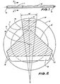
- Fig. I illustrates a rack made by a method in which the invention is embodied:
- Fig. 1 shows a typical Y-form rack bar made by a method in which the invention is embodied, the rack bar comprising toothed portion 1 and cylindrical portion 2.
- the rack bar comprising toothed portion 1 and cylindrical portion 2.
- ends of the rack are threaded as at 3 for the attachment of ball joints and tie rods.
- tie rods are fastened to the rack by rubber bushed studs located near the vehicle centre line, for which purpose the cylindrical part may be locally enlarged, drilled and tapped.
- the method to be described applies also to the manufacture of such racks.
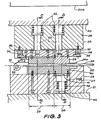
- Fig. II shows the appearance in section of the toothed portion of the Y-form rack seen at A-A of Fig. I and by circle 13, the cylindrical portion 2 of the rack bar.
- opposing guide faces 4 and 5 are symmetrically disposed about vertical axis 6 at an included angle 7 of say 90°.
- Teeth 8 terminate in oblique faces 9 and 10 in order to make optimum use of the space available in the inside of the steering housing tube, indicated by circle 11, centered at 12.
- Such oblique ends of the teeth of the rack also serve to reduce the chance of breakage of the teeth adjacent their ends.
- the cylindrical portion 2 indicated by line circle 13 is also centred at 12. The diameter is chosen so that its sectional area is substantially identical to the mean sectional area of the toothed portion 1; the stem of the "Y", 14, preferably has a slight taper of its opposing flanks as indicated by angle 15, giving it a dovetail shape.
- guide faces, 4 and 5 may be either convex or concave and arranged at an angle 7 other than 90 degrees, and stem 14 may have parallel sides or sides tapered opposite to that shown.
- guide faces 4 and 5 may extend to meet or to form a flat or radius.
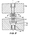
- Figs. III, IV and V show a preferred construction of a die for making racks of the type described, as installed in a press (not shown), having a movable platen 20 and fixed lower platen 21.
- the die comprises an upper-half die 22 and a lower-half die 23 secured to the respective upper and lower platen 20,21, of the press and in each of the three views are shown in the fully closed position as when rack bar 25 has been fully formed.
- the dies separate along axis 24 of the rack and upper platen 20 moves to raised position 20a for removal of the finished rack and insertion of a new blank to be formed.
- the die has two zones along the length of the rack, a gripping zone 38, and a forming zone 39, (Fig. III).
- gripping zone 38 As the upper-half die, 22, descends, gripping zone 38, a, section of which is shown in Fig. V, first engages rack bar blank 25 after which the several elements of forming zone 39 shown in section in Fig. IV form the entire toothed end of the rack in one blow.
- Gripping zone 38 comprises an upper gripper 29 and a lower gripper 40 each having grooves semicircular in section engaging rack bar blank 25 and loaded respectively by springs 32 and 42.
- Lower gripper 40 is secured to plunger 41 which is urged upwards by spring 42 housed in a chamber of lower bolster 27 of lower-half die 23.
- Upper gripper 29 (Fig. III) is secured to plate 28 which is urged downwards by springs 32.
- Plate 28 also carries upper die member 30 and block 31.
- Plate 28 is guided in upper bolster 26 through the action of guide pins 33 slidably journalled in upper bolster 26.
- Springs 32 act on the enlarged heads of guide pin 33.
- Plate 28 is limited in its downward travel by stop blocks 36 and 37 to about 8 mm as indicated by gaps 34 and 35 between plate 28 and respective stop blocks 36 and 37.
- FIG. IV Considering now a cross section of forming zone 39, (Fig. IV) it will be seen that in the fully closed position the rack is contained byfourdie elements; lower toothed die 44, hinged dies 47 and 48 and upper die member 30.
- Flank dies 45 and 46 may be made in one part with lower toothed die 44 but are here shown as being made separately for convenience of manufacture and servicing.
- Rolling dies 47 and 48 are supported by fulcrum blocks 49 and 50 secured to upper bolster 26.
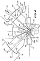
- Fig. VI is an enlarged scrap view of part of Fig. IV, showing on the rightsidethe position of the various die elements in the fully closed position as in Figs. III, IV and V, and on the left side the position of the elements of the die as the forming in zone 39 commences.
- Half circles centred at 24a and 24 illustrate the corresponding initial and final positions of the cylindrical portion of the rack bar blank 25.
- the cylindrical blank is loaded lengthwise into the open die resting on lower toothed die 44 and lower gripper 40 in its upper position and axially against end stop 51 which is pivotal about centre 52.
- upper gripper 29 first grips the cylindrical blank, (lefthand side Fig. VI) and as the die continues to close lower gripper 40 moves down (right-hand side Fig. VI) against the holding force of spring 42, until the shoulder of plunger 41 contacts the abutment 53A and the stop block 31, secured to plate 28, contacts end stop 51, thereby its downward motion is arrested.
- Upper die member 30 has now reached its fully closed position relative to lower toothed die 44.
- Fig. VII corresponds to that shown on the left side of Fig. VI where the downward motion of plate 28 has been arrested and forming of a blank has just commenced.
- Fig. VIII corresponds to the mid stroke, where the cylindrical blank has been deformed approximately as indicated by the dotted area 56.
- Fig. IX corresponds to the final position to that shown on the right side of Fig. VI where forming is complete including forming of the teeth.
- rolling dies 48 and 47 concentrate or focus the forming pressure in the toothed cavities of lower die 44, the most important area of the die to fill. Because rolling die 48, Fig. IX, is in contact with the flank die 46 for the last part of its travel, there is no place for the metal being formed to escape and hence become entrapped between the two die elements 48 and 46. Thus the highly-desirable, fully contained die cavity is provided.
- upper die member 30 may be shortened (while still acting as a guide for rolling dies 47, 48) so that the top of stem 14 remains rounded and is not flattened.
- rolling die 48 has a convex, part-cylindrical face 62, having a centre 63 engaged with a concave part-cylindrical seat 64 of the fulcrum block 50, having a centre 65.
- Contact between the face of 48 and seat of 50 must occur where the line joining 63 and 65 intersect them as at 68.
- the corresponding centres for the "up" position of the die are shown on the left side of Fig. VI and are indicated by 66 and 67, and in a similar manner contact between the seats will occur at 69. Very great loads can be carried between surfaces having nearly the same curvature.
- rolling dies 47 and 48 are maintained in their correct rolling relationship to fulcrum blocks 49 and 50 at all times by gear toothlike abutments 72 and 73 of fulcrum blocks 49 and 50, which engage corresponding abutments of hinged dies 47 and 48.
- the weight of rolling dies 47 and 48 may tend to make them depart from upper die member 30 in the open die position.
- a small spring (not shown) serves to ensure that contact as at 70 is maintained.
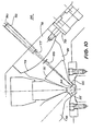
- Fig. X of another preferred embodiment is intended for use in the manufacture of racks by cold working.
- die elements 47 and 48 hereinbefore referred to as the rolling dies are replaced by oscillatory dies 74 and 75.
- the particular feature of the arrangement is the manner in which the working face of the die does not merely travel along line 57 as represented in Fig. VII, VIII and IX but, in addition, oscillates or rolls from side to side.
- face 5 of the rack be a flat face
- the working face 55 of oscillatory die 75 may be in the form, in section, of part of a cylinder, or other appropriate form.
- sliding block 76 In the configuration shown in Fig. X fulcrum blocks 49 and 50 are omitted and in their place is installed a sliding block 76.
- This sliding block is capable of an oscillatory movement of typically around 15mm. as indicated at 77, under the action of hydraulic cylinder 78 whose piston rod is attached to sliding block 76.
- the lower face of sliding block 76 is formed as part of a cylindrical surface 79, having a longitudinal axis centred at 80.
- sliding block 76 On this cylindrical surface is arranged to slide oscillatory die holder 81 to which is secured oscillatory die 75. Both the upper and lower surfaces of sliding block 76 are equipped with pockets into which is forced a fluid at extremely high pressure so that the free motion of the h d sliding block under the action of cylinder 78 is permitted without excessive friction.
- cylinder 78 oscillates the sliding block over distance 77, so causing the longitudinal axis of cylindrial surface 79 to oscillate over the distance 82 which is of the same magnitude as distance 77.
- oscillatory die 75 oscillates through some angle 83 so that its working face which as stated earlier may be part of a cylinder, having a longitudinal axis centred at 80 rolls cyclically across the longitudinal guide surface of the rack being formed.
- the left hand of the die arrangement which is symmetrical with that just described and provision is made so that the oscillation of the left hand sliding block is coordinated with that of the right sliding block.
- a cylindrical blank 25 is inserted as shown on the left hand side of Fig. X and oscillation of the device is commenced.
- upper bolster 26 descends under the action of a hydraulic cylinder or in a press and therefore the blank 25 is successively deformed ,and rolled into the final shape as indicated on the righthand side of Fig. X.
- a carbon steel for example 1050 steel, may be formed in a die of this construction in a manner which may not be possible in the die described earlier because of the onset of work hardening typical of such materials. It will be appreciated however that the construction of such a die is significantly more complex and thus more costly than that described in connection with Fig. VI.
- the entire die can be placed in a conventional forging or hydraulic press and the angular motion of the die elements described is obtained by the mechanism of the die itself.
- a special press could be constructed in which the downward and inward travel of the presently rolling die elements is replaced by direct travel of the angled dies along, for example, line 57.
- Such a press might be particularly advantageous if it were of hydraulic operation in that it would be very compact and of relatively low cost providing that a number of such presses were to be made.
- a forging press having two angled rams would be complicated and expensive machine.
Landscapes
- Engineering & Computer Science (AREA)
- Mechanical Engineering (AREA)
- Chemical & Material Sciences (AREA)
- Combustion & Propulsion (AREA)
- Transportation (AREA)
- Forging (AREA)
Applications Claiming Priority (2)
| Application Number | Priority Date | Filing Date | Title |
|---|---|---|---|
| AUPF430982 | 1982-06-04 | ||
| AU4309/82 | 1982-06-04 |
Publications (3)
| Publication Number | Publication Date |
|---|---|
| EP0110918A1 EP0110918A1 (en) | 1984-06-20 |
| EP0110918A4 EP0110918A4 (en) | 1985-07-30 |
| EP0110918B1 true EP0110918B1 (en) | 1989-08-30 |
Family
ID=3769574
Family Applications (1)
| Application Number | Title | Priority Date | Filing Date |
|---|---|---|---|
| EP83901696A Expired EP0110918B1 (en) | 1982-06-04 | 1983-06-02 | Method and apparatus for making steering rack bars |
Country Status (11)
| Country | Link |
|---|---|
| US (2) | US4571982A (fa) |
| EP (1) | EP0110918B1 (fa) |
| AR (1) | AR231702A1 (fa) |
| BR (1) | BR8307391A (fa) |
| CA (1) | CA1204005A (fa) |
| DE (1) | DE3380481D1 (fa) |
| ES (1) | ES523255A0 (fa) |
| IN (1) | IN158109B (fa) |
| IT (1) | IT1163449B (fa) |
| SU (1) | SU1521276A3 (fa) |
| ZA (1) | ZA834029B (fa) |
Cited By (5)
| Publication number | Priority date | Publication date | Assignee | Title |
|---|---|---|---|---|
| DE19839428A1 (de) * | 1998-08-29 | 2000-03-02 | Zahnradfabrik Friedrichshafen | Verfahren zur Herstellung einer Zahnstange und Prägevorrichtung zum Durchführen des Verfahrens |
| DE19901425A1 (de) * | 1999-01-18 | 2000-07-27 | Umformtechnik Bauerle Gmbh | Rohrförmiges Zahnstangenwerkstück und Verfahren zu dessen Herstellung, insbesondere für Zahnstangenlenkungen von Kraftfahrzeugen |
| DE10203888A1 (de) * | 2002-01-31 | 2003-08-21 | Zf Lenksysteme Gmbh | Verfahren und Vorrichtung zum Herstellen einer Zahnstange |
| CN102481618A (zh) * | 2009-08-12 | 2012-05-30 | 毕晓普操纵技术私人股份公司 | 用于转向齿条的锻模设备 |
| KR20220147763A (ko) * | 2021-04-27 | 2022-11-04 | 주식회사 코우 | 스티어링 샤프트 및 그 제조방법 |
Families Citing this family (22)
| Publication number | Priority date | Publication date | Assignee | Title |
|---|---|---|---|---|
| US5242514A (en) * | 1988-06-07 | 1993-09-07 | Richard Wiener | Method for the production of a hardened guide shaft for a linear guide |
| AUPM302693A0 (en) * | 1993-12-16 | 1994-01-20 | A.E. Bishop & Associates Pty Limited | Apparatus for manufacturing steering rack bars |
| AU676628B2 (en) * | 1993-12-16 | 1997-03-13 | Bishop Steering Technology Limited | Apparatus for manufacturing steering rack bars |
| DE9407856U1 (de) * | 1994-05-11 | 1995-10-26 | Ferco International, Sarrebourg | Treibstangenelement für Treibstangenbeschläge |
| US6047581A (en) * | 1998-02-27 | 2000-04-11 | Anderson Cook, Inc. | Drive system for vertical rack spline-forming machine |
| US5950471A (en) * | 1998-02-27 | 1999-09-14 | Anderson-Cook, Inc. | Vertical rack spline forming machine |
| KR100422996B1 (ko) * | 1998-12-25 | 2004-03-18 | 다카시마 가부시키 가이샤 | 보강 부재 |
| US20050178818A1 (en) * | 1998-12-25 | 2005-08-18 | Kiyokazu Kobayashi | Method of joining steel members, method of processing joined surface of steel member and reinforcing member |
| US6845560B2 (en) * | 2000-03-09 | 2005-01-25 | Nsk Ltd. | Method for manufacturing a hollow rack shaft |
| US6615635B2 (en) * | 2000-06-20 | 2003-09-09 | Ina Walzlager Schaeffler Ohg | Method of making a lever-type cam follower, and lever-type cam follower |
| DE60209332T2 (de) * | 2001-03-22 | 2006-10-05 | Bishop Innovation Ltd., North Ryde | Verfahren und vorrichtung zur herstellung einer geschmiedeten zahnstange |
| CN100364832C (zh) * | 2003-09-23 | 2008-01-30 | 毕晓普创新有限公司 | 复合式转向齿条及其制造方法 |
| EP1694453B1 (en) * | 2003-12-04 | 2011-08-31 | Bishop Innovation Pty Ltd | Apparatus for and method of steering rack manufacture |
| US7950153B2 (en) * | 2005-03-23 | 2011-05-31 | Bishop Innovation Limited | Method of manufacturing a steering rack |
| WO2011065297A1 (ja) * | 2009-11-26 | 2011-06-03 | 株式会社ゴーシュー | 板状歯形部材の製造装置 |
| EP2569116B1 (en) | 2010-05-10 | 2018-05-23 | Bishop Steering Technology Pty Ltd | Die apparatus and method for forging steering racks |
| CN101947618B (zh) * | 2010-09-08 | 2012-03-14 | 上海运良企业发展有限公司 | 超长圆柱体毛坯镦粗模具 |
| FR2965496B1 (fr) * | 2010-09-30 | 2013-07-12 | Snecma | Outillage de forme « multi-effets » apte au formage a haute temperature. |
| US9518627B2 (en) * | 2014-11-26 | 2016-12-13 | Steering Solutions Ip Holding Corporation | Changes enabling the elimination of processes for a torsion bar |
| US10828693B2 (en) * | 2015-05-14 | 2020-11-10 | Nippon Steel Corporation | Apparatus for manufacturing forged crankshaft |
| WO2018094451A1 (en) | 2016-11-27 | 2018-05-31 | Bishop Steering Technology Pty Ltd | Die apparatus for forging steering racks |
| DE102021124673A1 (de) | 2021-09-23 | 2023-03-23 | OSRAM CONTINENTAL GmbH | Vorrichtung und Verfahren zur Strangpressextrusion mit anschließender Geometrieänderung |
Family Cites Families (14)
| Publication number | Priority date | Publication date | Assignee | Title |
|---|---|---|---|---|
| US355304A (en) * | 1887-01-04 | Mechanism for bending metal | ||
| US1771681A (en) * | 1927-09-06 | 1930-07-29 | Kahn Julius | Rib-forming die |
| US2064956A (en) * | 1931-02-28 | 1936-12-22 | Harrisburg Steel Corp | Apparatus for producing an improved forged steel tractor shoe |
| US2074705A (en) * | 1934-04-11 | 1937-03-23 | Gen Motors Corp | Method and device for forming paper |
| US2066186A (en) * | 1935-07-02 | 1936-12-29 | Cleveland Tractor Co | Truing die and method |
| US3550418A (en) * | 1969-06-10 | 1970-12-29 | Cannell J Mcleod | Rack gear formation |
| DE2446413C3 (de) * | 1974-09-28 | 1978-12-07 | Kabel- Und Metallwerke Gutehoffnungshuette Ag, 3000 Hannover | Vorrichtung zum spanlosen Herstellen von Kegelzahnrädern |
| GB1525760A (en) * | 1975-12-31 | 1978-09-20 | Bishop A | Rack and pinion steering gear |
| US4044592A (en) * | 1976-05-19 | 1977-08-30 | Gulf & Western Manufacturing Company | Coining die assembly |
| US4091652A (en) * | 1977-01-28 | 1978-05-30 | Alumax, Inc. | Apparatus for shaping metal sheets |
| US4133221A (en) * | 1977-06-23 | 1979-01-09 | Trw, Inc. | Rack gear and method of making the same |
| GB2056894B (en) * | 1979-08-30 | 1982-12-15 | Cam Gears Ltd | Manufacture of rack member for rack and pinion assembly |
| GB2088256B (en) * | 1980-12-03 | 1984-04-11 | Jidosha Kiki Co | Manufacturing toothed racks |
| JPS62734A (ja) * | 1985-06-27 | 1987-01-06 | Yamatake Honeywell Co Ltd | 調理装置 |
-
1983
- 1983-06-02 BR BR8307391A patent/BR8307391A/pt not_active IP Right Cessation
- 1983-06-02 EP EP83901696A patent/EP0110918B1/en not_active Expired
- 1983-06-02 US US06/572,424 patent/US4571982A/en not_active Expired - Lifetime
- 1983-06-02 DE DE8383901696T patent/DE3380481D1/de not_active Expired
- 1983-06-03 CA CA000429672A patent/CA1204005A/en not_active Expired
- 1983-06-03 AR AR293246A patent/AR231702A1/es active
- 1983-06-03 ZA ZA834029A patent/ZA834029B/xx unknown
- 1983-06-03 ES ES523255A patent/ES523255A0/es active Granted
- 1983-06-03 IT IT8321449A patent/IT1163449B/it active
- 1983-06-04 IN IN708/CAL/83A patent/IN158109B/en unknown
-
1984
- 1984-02-03 SU SU843709066A patent/SU1521276A3/ru active
-
1986
- 1986-01-16 US US06/819,291 patent/US4715210A/en not_active Expired - Lifetime
Cited By (6)
| Publication number | Priority date | Publication date | Assignee | Title |
|---|---|---|---|---|
| DE19839428A1 (de) * | 1998-08-29 | 2000-03-02 | Zahnradfabrik Friedrichshafen | Verfahren zur Herstellung einer Zahnstange und Prägevorrichtung zum Durchführen des Verfahrens |
| DE19901425A1 (de) * | 1999-01-18 | 2000-07-27 | Umformtechnik Bauerle Gmbh | Rohrförmiges Zahnstangenwerkstück und Verfahren zu dessen Herstellung, insbesondere für Zahnstangenlenkungen von Kraftfahrzeugen |
| DE19901425C2 (de) * | 1999-01-18 | 2002-12-05 | Umformtechnik Baeuerle Gmbh | Verfahren zur Herstellung eines rohrförmigen Zahnstangenwerkstückes, insbesondere für Zahnstangenlenkungen von Kraftfahrzeugen |
| DE10203888A1 (de) * | 2002-01-31 | 2003-08-21 | Zf Lenksysteme Gmbh | Verfahren und Vorrichtung zum Herstellen einer Zahnstange |
| CN102481618A (zh) * | 2009-08-12 | 2012-05-30 | 毕晓普操纵技术私人股份公司 | 用于转向齿条的锻模设备 |
| KR20220147763A (ko) * | 2021-04-27 | 2022-11-04 | 주식회사 코우 | 스티어링 샤프트 및 그 제조방법 |
Also Published As
| Publication number | Publication date |
|---|---|
| ZA834029B (en) | 1984-03-28 |
| ES8502007A1 (es) | 1984-12-16 |
| US4715210A (en) | 1987-12-29 |
| IT8321449A0 (it) | 1983-06-03 |
| US4571982A (en) | 1986-02-25 |
| BR8307391A (pt) | 1984-05-08 |
| CA1204005A (en) | 1986-05-06 |
| IT1163449B (it) | 1987-04-08 |
| IN158109B (fa) | 1986-09-06 |
| AR231702A1 (es) | 1985-02-28 |
| EP0110918A1 (en) | 1984-06-20 |
| DE3380481D1 (en) | 1989-10-05 |
| SU1521276A3 (ru) | 1989-11-07 |
| ES523255A0 (es) | 1984-12-16 |
| EP0110918A4 (en) | 1985-07-30 |
Similar Documents
| Publication | Publication Date | Title |
|---|---|---|
| EP0110918B1 (en) | Method and apparatus for making steering rack bars | |
| KR100815463B1 (ko) | 스티어링 랙 제조 | |
| US4094183A (en) | Method of fabricating a substantially U-shaped body and apparatus for the performance thereof | |
| US3650143A (en) | Apparatus for forging crankshafts and the like | |
| US3793703A (en) | Process for fabricating rear axle housing for motor vehicles | |
| US3889512A (en) | Steering knuckles and method of forming the same | |
| KR100418464B1 (ko) | 언벤딩 형상의 예비성형체를 이용하는 크랭크스로우 단조공법 및 단조장치 | |
| JPH10180394A (ja) | 端部異形棒状製品の鍛造方法および鍛造装置 | |
| US4272979A (en) | Method and apparatus for forging crank throws | |
| CN110014105A (zh) | 一种变形短t型坯件的锻造方法 | |
| WO1983004197A1 (en) | Method and apparatus for making steering rack bars | |
| JPH11320013A (ja) | 端部異形棒状製品の鍛造方法および鍛造装置 | |
| US3595011A (en) | Method of forming chain side bars with curved bearing surfaces | |
| US3940969A (en) | Apparatus and method for forging a bicycle crank | |
| US3010186A (en) | Piston manufacture | |
| KR20120083283A (ko) | 스티어링 랙용 단조 금형 장치 | |
| US20070277579A1 (en) | Method And Tool For Closed Die Forging | |
| CN214814543U (zh) | 一种前轴板簧精压校正装置 | |
| CN110899411B (zh) | 一种弯臂转向节折弯成形系统及方法 | |
| JP4054153B2 (ja) | 孔を有する鍛造部品の製造方法および製造装置 | |
| SU1234031A1 (ru) | Штамп дл штамповки поковок с ребрами | |
| EP3453471B1 (en) | Upsetting device and press | |
| US3858429A (en) | Apparatus and process for fabricating rear axle housings for motor vehicles | |
| US3518892A (en) | Chain in which the side bars are formed with curved bearing surfaces | |
| CN217451599U (zh) | 一种铝合金型材加工使用的折弯装置 |
Legal Events
| Date | Code | Title | Description |
|---|---|---|---|
| PUAI | Public reference made under article 153(3) epc to a published international application that has entered the european phase |
Free format text: ORIGINAL CODE: 0009012 |
|
| 17P | Request for examination filed |
Effective date: 19830915 |
|
| AK | Designated contracting states |
Designated state(s): DE FR GB SE |
|
| 17Q | First examination report despatched |
Effective date: 19860912 |
|
| GRAA | (expected) grant |
Free format text: ORIGINAL CODE: 0009210 |
|
| AK | Designated contracting states |
Kind code of ref document: B1 Designated state(s): DE FR GB SE |
|
| REF | Corresponds to: |
Ref document number: 3380481 Country of ref document: DE Date of ref document: 19891005 |
|
| ET | Fr: translation filed | ||
| PLBE | No opposition filed within time limit |
Free format text: ORIGINAL CODE: 0009261 |
|
| STAA | Information on the status of an ep patent application or granted ep patent |
Free format text: STATUS: NO OPPOSITION FILED WITHIN TIME LIMIT |
|
| 26N | No opposition filed | ||
| PGFP | Annual fee paid to national office [announced via postgrant information from national office to epo] |
Ref country code: SE Payment date: 19940622 Year of fee payment: 12 |
|
| EAL | Se: european patent in force in sweden |
Ref document number: 83901696.1 |
|
| PG25 | Lapsed in a contracting state [announced via postgrant information from national office to epo] |
Ref country code: SE Effective date: 19950603 |
|
| EUG | Se: european patent has lapsed |
Ref document number: 83901696.1 |
|
| REG | Reference to a national code |
Ref country code: GB Ref legal event code: IF02 |
|
| PGFP | Annual fee paid to national office [announced via postgrant information from national office to epo] |
Ref country code: FR Payment date: 20020524 Year of fee payment: 20 |
|
| PGFP | Annual fee paid to national office [announced via postgrant information from national office to epo] |
Ref country code: GB Payment date: 20020527 Year of fee payment: 20 |
|
| PGFP | Annual fee paid to national office [announced via postgrant information from national office to epo] |
Ref country code: DE Payment date: 20020628 Year of fee payment: 20 |
|
| PG25 | Lapsed in a contracting state [announced via postgrant information from national office to epo] |
Ref country code: GB Free format text: LAPSE BECAUSE OF EXPIRATION OF PROTECTION Effective date: 20030601 |
|
| REG | Reference to a national code |
Ref country code: GB Ref legal event code: PE20 |