EP0110680B1 - Gerät zur magnetischen Aufnahme und Wiedergabe - Google Patents
Gerät zur magnetischen Aufnahme und Wiedergabe Download PDFInfo
- Publication number
- EP0110680B1 EP0110680B1 EP83307180A EP83307180A EP0110680B1 EP 0110680 B1 EP0110680 B1 EP 0110680B1 EP 83307180 A EP83307180 A EP 83307180A EP 83307180 A EP83307180 A EP 83307180A EP 0110680 B1 EP0110680 B1 EP 0110680B1
- Authority
- EP
- European Patent Office
- Prior art keywords
- signal
- recording
- reproducing
- rotary transformer
- drum
- Prior art date
- Legal status (The legal status is an assumption and is not a legal conclusion. Google has not performed a legal analysis and makes no representation as to the accuracy of the status listed.)
- Expired
Links
Images


Classifications
-
- G—PHYSICS
- G11—INFORMATION STORAGE
- G11B—INFORMATION STORAGE BASED ON RELATIVE MOVEMENT BETWEEN RECORD CARRIER AND TRANSDUCER
- G11B15/00—Driving, starting or stopping record carriers of filamentary or web form; Driving both such record carriers and heads; Guiding such record carriers or containers therefor; Control thereof; Control of operating function
- G11B15/02—Control of operating function, e.g. switching from recording to reproducing
- G11B15/12—Masking of heads; circuits for Selecting or switching of heads between operative and inoperative functions or between different operative functions or for selection between operative heads; Masking of beams, e.g. of light beams
- G11B15/14—Masking or switching periodically, e.g. of rotating heads
Definitions
- This invention relates to a magnetic recording and reproducing apparatus having a rotor drum mounting thereon a plurality of rotary magnetic heads, reproducing amplifiers, so that recording and reproducing signals can be amplified and switched on the rotor drum.
- a rotary transformer is used for signal transmission between rotary magnetic heads and stator circuits.
- the number of the transmitting channels of the rotary transformer must be equal to that of the rotary magnetic heads. Accordingly, if the number of the rotary magnetic heads increases, the size of rotary transformer is large and disturbance to video signals occurs because of cross-talk between adjacent channels. Further, since reproduced signals from the rotary magnetic heads are required to be broad-band for obtaining high efficiency, the reproducing amplifiers must be placed as closely as possible to the rotary magnetic heads for decreasing stray capacitance.
- Fig. 1 shows an example of a conventional magnetic recording and reproducing apparatus.
- 1a-1d show rotary magnetic heads
- 9 shows a magnetic recording medium such as a magnetic tape.
- the rotary magnetic heads 1a-1d are coupled to stator circuits through a rotary transformer 3.
- 2a-2d show channels of the rotary transformer 3 and the broken line shows the group of channels 2a-2d of the rotary transformer 3.
- Each of the rotary magnetic heads 1a-1d is connected to each of the channels 2a 2d of the rotary transformer 3 as showm Fig. 1, which means the number of the channels of the rotary transformer is equal to that of the rotary magnetic heads.
- the channels 2a-2d of the rotary transformer 3 are coupled to reproducing amplifiers 5a-5d through recording/reproducing mode switching circuits 4a-4d.
- the reproducing amplifiers 5a-5d are connected to a reproducing head selection circuit 6.
- the mode switching circuits 4a-4d further connected with a recording head selection circuit 7 which is connected with a recording amplifier 8.
- the mode switching circuits 4a-4d select the reproducing mode by a recording/reproducing mode switching signal.
- the reproduced signals are transferred to the reproducing amplifiers 5a-5d.
- the amplified signals are transferred to the reproducing head selection circuit 6 which selects a reproducing magnetic head according to a head selection signal to obtain the desired reproduced signal.
- a recording signal amplified by the recording amplifier 8 is transferred to a recording magnetic head which is selected by the recording head selection circuit 7 through one of the mode switching circuits 4a-4d and one of the channels 2a-2d of the rotary transformer 3.
- the mode switching circuits 4a-4d prevent the recording signal from being transferred to the reproducing amplifiers 5a-5d.
- the rotary transformer 3 is usually installed in the cylinder unit and the mode switching circuits 4a-4d and the reproducing amplifiers 5a-5d are installed on a printed board at the stator drum side together with other circuit blocks. Since the rotary magnetic heads are distant from the printed board, the connection wires between the rotary transformer and the circuits on the printed board are shielded and the stray capacitance is approximately 40 80 pF. Accordingly, the frequency characteristic during playback mode cannot be wide. In other words, such a conventional example as above is unsuitable for broadening the frequency band of the amplifiers.
- Fig. 1 shows the example using four rotary magnetic heads, but the number of the rotary magnetic heads must be increased for the special reproducing and the long play-and-audio reproducing. Therefore, the channels of the rotary transformer will increase and accordingly the size thereof will increase. This means that the number of the rotary magnetic heads practically mountable to the rotor drum is limited.
- An object of this invention is to provide a magnetic recording/reproducing apparatus having broad-band and high S/N reproducing amplifier system and a small-sized rotary cylinder unit.
- the present invention provides a magnetic recording/reproducing apparatus having a cylinder unit comprising a rotor drum, a stator drum, a rotary transformer for transmitting signals between said rotor and stator drums, and a plurality of magnetic heads mounted on said rotor drum each for recording video signals on a magnetic recording medium wound on said cylinder unit and reproducing the recorded video signals from said recording medium, characterized in that said rotary transformer has a first channel for reversibly transmitting video signals between said rotor drum and said stator drum and a second channel for transmitting from said stator drum to said rotor drum a control signal which contains a carrier signal modulated by a recording/reproducing mode switching signal and a head selection signal, and in that said rotor drum has mounted thereon: amplifying means for amplifying video signals reproduced by said plurality of magnetic heads; recording/reproducing mode switching means for coupling said pluralit
- head selecting means for selecting one of said plurality of magnetic heads
- control means for obtaining said recording/ reproducing mode selection signal and said selection signal for controlling said mode switching means and said head selecting means respectively, from said control signal transmitted from said stator drum through said channel of said rotary transformer and
- a power source for producing a DC voltage for energizing all of said means on said rotor drum from said control signal transmitted from said stator drum through said second channel of said rotary transformer.
- Fig. 2 shows an exploded perspective view of an embodiment of a cylinder unit of this invention.
- 1a, 1b are rotary magnetic heads mounted on a rotor drum 11.
- 14 is the rotor side of a rotary transformer, which is fixed to the rotor drum 11 with the rotary disk 13.
- 15 is the stator side of the rotary transformer, which is fixed to a stator drum 16. Signals are transmitted between the rotor side 14 of the rotary transformer and the stator side 15 of the rotary transformer.
- the gap between the rotary and stator sides is about 100 pm.
- 12 is a signal processing circuit on the rotor drum 11, for amplifying signals and selecting recording/reproducing head.
- Fig. 3 shows a basic block diagram showing an embodiment of a magnetic recording/reproducing apparatus of this invention.
- 1a-1d are rotary magnetic heads.
- a rotary transformer 17 consists of two channels 18a and 18b.
- the channel 18a transmits the recording and reproduced signals between the rotor side and the stator side, and the channel 18btransmits both a carrier signal and a control signal for selecting a head and switching the recording/reproducing mode.
- Recording/reproducing mode switching circuits 4a-4d and 19, the reproducing amplifiers 5a-5d, the reproducing head selection circuit 6 and the recording head selection circuit 7 are located between the rotary magnetic heads 1a-1d and the rotor side of the channel 18a of the rotary transformer 17.
- the circuit connections of these circuit elements are the same as those shown in Fig. 1.
- the rotary magnetic heads 1a-1d are connected with the reproducing amplifiers 5a-5d by the mode switching circuits 4a 4d.
- the recording head selection circuit 7 is disconnected from the rotary magnetic heads 1a-1d by the mode switching circuits 4a-4d.
- the specific signal is selected by the reproducing head selection circuit 6 and is transmitted to the circuit block at the stator side through the recording/ reproducing mode switching circuit 19 and to the channel 18a of the rotary transformer 17.
- the recording head selection circuit 7 is disconnected from the channel 18a of the rotary transformer 17.
- the reproducing amplifiers 5a-5d are disconnected from the magnetic heads 1a-1d by the mode switching circuits 4a-4d and the recording signal transmitted through the channel 18a of the rotary transformer 17 is applied to the specific one of the magnetic heads 1a-1d through the mode switching circuit 19, the recording head selection circuit 7, and the specific one of the mode switching circuits 4a-4d.
- An alternating current signal containing the information for switching the recording/reproducing mode and selecting the specific head is transmitted through the channel 18b of the rotary transformer 17, and applied to a first and a second control circuits 21 and 22 generating control signals for mode switching and head selection, respectively.
- the first and second control circuits 21 and 22 are also mounted on the rotor drum.
- the present invention needs a DC power source on the rotor drum as shown in Fig. 3, for supplying power to the circuits mounted on the rotor drum.
- the alternating signal transmitted through the channel 18b is applied also to the DC power source 23.
- the DC power supply 23 rectifies and smoothes the alternating signal to produce a DC voltage.
- band characteristic can be obtained. Further, high S/N can be realized because the signal reproduced by the magnetic head is transmitted through the rotary transformer after being amplified to adequately high level. Also, since only one signal is transmitted through the rotary transformer, the number of the channel of the rotary transformer needs not be increased when the number of the rotary magnetic heads is increased.
- the alternating signal is composed of a carrier, a recording/reproducing switching signal and a head selection signal.
- the frequency of the carrier is set at the lower portion of the transmittable frequency band of the rotary transformer.
- the frequency area during recording or reproducing is the down-converted chrominance signal and the frequency modulated luminance signal (usually, 200 KHz-5 MHz).
- the signal of several hundreds KHz-several MHz is transmitted through the rotary transformer. Because of the construction of the rotary transformer, it is unavoidable to suffer from the cross-talk between adjacent channels. In this case, it is desirable that the carrier frequency area of the alternating signal which is supplied to the DC power supply and the control circuits is set at a frequency outside the above frequency band.
- the rotary transformer actually has the transmittable frequency band of 50 KHz-several MHz.
- the signal frequency area of the down-converted chrominance recording method and the transmitted character of the rotary transformer when we will put the reproducing amplifiers on the rotary drum, we must set the frequency of the alternating signal which is supplied to the DC power supply on the rotor drum must be set atthe low-band of the down-converted chrominance signal and within the transmittable band of the rotary transformer. It is needless to say that the frequency of the alternating signal should be set below the lower frequency of the down-converted chrominance signal, if it is within the transmittable band of the rotary transformer.
- the down-converted chrominance recording method is explained as an example. But it is needless to say that the above condition is applicable to other recording methods, for example, the magnetic recording/ reproducing apparatus which transmits the luminance signal and the chrominance signal through different channels of the rotary transformer.
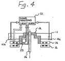
- Fig. 4 shows a cross-sectional view of the rotor drum.
- the DC power supply 23 rectifies and smoothes the alternating signal transmitted from the stator drum side and produces a DC voltage, when harmonic wave signals can be also generated.
- the signal reproduced from the rotary magnetic heads 10a, 10b is several hundred nVp-p' compared that the alternating signal is several Vp-27. Accordingly, the alternating signal can disturb the reproduced signal.
- the DC power supply 23 is disposed inside the rotary disk to be shielded by the rotary disk so that the rotary magnetic heads will not suffer from the disturbance of the alternating signal.
- Fig. 5 shows a basic block diagram showing another embodiment of this invention.
- the output signal of an erase/bias oscillator 27 which supplies signals to an exase head 25 (fixed head) and an audio head 26 (fixed head) is used as the alternating signal transmitted to the channel 18b, and accordingly to the DC power supply 23 and the control circuits 21 and 22.
- the erase/bias oscillator 27 supplies an erase current to the erase head 25 and a bias current to the audio head 26, for erasing recorded video and audio signals on the magnetic tape.
- the oscillating frequency of the erase/ bias oscillator 27 is 60 KHz-120 KHz which is several times the upmost frequency of audio signal. Since the transmittable frequency band of the rotary transformer 17 is 50 KHz-several MHz, the output signal (about 100 KHz) of the erase/bias oscillator 27 can be directly transmitted to the rotor drum side through the rotary transformer 17. Even if there is a cross-talk between the channels of the rotary transformer, the alternating signal will not disturb the reproduced video signal because the transmitted band of the video signal is 100 KHz-5 MHz.
- Fig. 6 shows a basic block diagram showing still another embodiment of this invention.
- the output signal of an oscillator 28 for flying erase is used as the alternating signal transmitted to the DC power supply 23 and the control circuits 21, 22.
- This method also simplifies the circuit configuration.
- 1 e is a rotary magnetic head for flying erase, which usually has a gap several-ten times large as that of the recording/reproducing heads, and is supplied with a high frequency current of more than 4 MHz, thereby to erase video signals recorded on video tracks on the magnetic tape.
- Fig. 1 e is a rotary magnetic head for flying erase, which usually has a gap several-ten times large as that of the recording/reproducing heads, and is supplied with a high frequency current of more than 4 MHz, thereby to erase video signals recorded on video tracks on the magnetic tape.
- the track width of the rotary magnetic head 1e for flying erase is two times larger than that of the rotary magnetic heads 1a-1d for recording/reproducing, so that the rotary magnetic head for flying erase can erase two video tracks (corresponding to one frame) by a scan.
- the recorded signals can be erased field by field (one field erase).
- the output signal of the oscillator 28 for flying erase is amplified by an amplifier 29 and transmitted to the rotary magnetic head 1 e for flying erase through the channel 18b of the rotary transformer 17.
- This alternating signal is also transmitted to the DC power supply 23, and converted to a DC voltage used as the supply voltage to the circuit elements on the rotor drum.
- Fig. 7 shows a basic block diagram showing a further embodiment of this invention.
- 30 is a modulation circuit which generates a signal modulated by the recording/reproducing mode switching signal and the head selection signal.
- This modulated signal is amplified by the amplifier 29 and transmitted through the channel 18b to a demodulation circuit 31 which demodulates the modulated signal.
- frequencies corresponding to recording and reproducing are assigned to carriers and frequencies corresponding to the rotary magnetic heads are assigned to the control signals.
- the alternating signal frequency-modulated by the control signal is amplified by the amplifier 29 and transmitted to the demodulation circuit 31 through the channel 18b of the rotary transformer 17.
- control signal and the carrier which are demodulated by the demodulation circuit 31 are applied to the control circuits 21, 22 and the DC power supply 23, respectively. Accordingly, during recording or reproducing mode the specific head can be selected and the DC voltage can energize all the circuit elements on the rotor drum.
- Fig. 8 shows a basic block diagram showing a still further embodiment of this invention.
- the basic configuration is the same as that of the embodiment shown Fig. 7, but it is different that a switch 32 is connected to the modulation circuit 30 which switches the head selection signal according to recording/reproducing mode switching signal.
- the switch 32 turns on so that the alternating signal modulated by the head selection signal is transmitted through the channel 18b to the rotor drum side, and all the circuits on the rotor drum becomes the reproducing mode by the operation of the recording/reproducing mode switching circuit 21.
- the switch 32 turns off so that the alternating signal not-modulated is transmitted to the rotor drum side, and all the circuits on the rotor drum becomes recording mode by the operation of the recording/reproducing mode switching circuit 21. In other words, discrimination of the recording and reproducing mode can be achieved simply by ON/OFF operation of the switch 32.
- Fig. 9 is a detailed circuit diagram showing further another embodiment of the present invention.
- the circuits shown in Fig. 9 can be employed for all of the previously described embodiments with a simple modification, because most part of the circuit arrangement in Fig. 9 is the same as those of the previously described embodiments except that the rotary transformer has a third channel 198c.
- the recording/reproducing mode switching circuits 4a-4d comprises switches 170a-170d and 171a-171b; the reproducing head selection circuit 6 comprises selection switches 172a-172d, 174a and 174b; and the recording head selection circuit 7 comprises selection switches 173a-173d, 175a and 175b.
- the switches 170a-170d are OFF and the switches 171a-171d are ON, so that the reproduced signal from the rotary magnetic heads 1a-1d is applied to the reproducing amplifiers 5a-5d, and a specific signal is selected by the selection switches 172a-172d, 174a and 174b.
- the switches 170a-170d are ON and the switches 171a-171d are OFF, so that the recording signal can be applied to a specific one of the rotary magnetic head 1a-1d selected by the selection switches 173a-173d, 175a and 175b.
- control circuits for producing control signals for switching mode and selecting head will be described.
- Fig. 10 is wave form diagrams for explaining the operation of the control circuits in Fig. 9.
- the resistance values Ra, Rb, Rc, Rd of the respective resistors 195a-195d are selected to be Ra>Rb>Rc>Rd.
- Switches 196a, 196b, 197a, 197b are controlled by the first and second head selection signals.
- Fig. 10, A-1 and A-2 show the wave form at point A of the circuit shown in Fig.10
- A-1 is the wave form when the selection switch 197a is ON and A-2 is the wave form when the selection switch 197b is ON. Accordingly, an amplitude-modulated (AM) signal can be obtained from the carrier and the head selection signals.
- AM amplitude-modulated
- the AM signal is transmitted through the channel 198b of the rotary transformer and applied to a DC voltage generating circuit 16 and a head selection signal generating circuit 21.
- the AM signal is detected by a diode 178, a capacitor 179 and a resistor 180 and the signal as shown in Fig. 10, B-1, B-2 can be obtained at point B in Fig. 9.181 is a voltage comparator and 182 is a reference voltage source generating a reference voltage V 1 .
- the voltage comparator 181 compares the signals shown in B-1 and B-2 with the reference voltage V, thereby to obtain the output signals as shown in Fig. 10, E-1 and E-2, respectively.
- the switches 174a-174d can be controlled by the second head selection signal given at the stator drum side.
- 183 is an inverter.
- the detected signal obtained through the capacitor 184 is amplified by a transistor 187 thereby to obtain the first head selection signal.
- the base of the transistor 187 is biased to be V 2 by resistors 186 and 185.
- the wave form at the base and the collector of the transistor 187 are shown in Fig. 10, C-1, C-2 and D-1, D-2, respectively.
- 188 is an inverter. Accordingly, the switches 172a-172d and 173a-173d can be controlled by the first head selection signal given at the stator drum side.
- the recording/reproducing mode switching can be controlled by the signal transmitted through the channel 198c of the rotary transformer.
- the recording/reproducing mode switching signal given at the stator drum side is transmitted through the channel 198c to the control circuit comprising a diode 189, a capacitor 190 and a transistor 191 which detect the transmitted signal, a reference voltage source 193 and a voltage comparator 192 for comparing the detected signal level with the output signal level of the reference voltage source 193.
- the output signal of the comparator 192 controls the switches 170a-170d, 171a-171d and 176a, 176b.
- the alternating signal (carrier) is amplitude-modulated by the head selection signals and transmitted to the rotor drum side circuits through the channel 198b of the rotary transformer, and the recording/reproducing mode switching signal is transmitted to the rotor drum side circuits through the channel 198c of the rotary transformer.
- the recording/reproducing mode switching circuits 4a-4d can be substituted by a circuit which performs the mode switching and the head selection functions.
- the reproducing amplifiers 5a-5d can be substituted by a single amplifier, and the head selection circuits 6 and 7 can be removed, thereby to more simplifying the circuit configuration.
Claims (8)
Applications Claiming Priority (4)
| Application Number | Priority Date | Filing Date | Title |
|---|---|---|---|
| JP20669482A JPS5996508A (ja) | 1982-11-24 | 1982-11-24 | 磁気記録再生装置 |
| JP206695/82 | 1982-11-24 | ||
| JP20669582A JPS5996509A (ja) | 1982-11-24 | 1982-11-24 | 磁気記録再生装置 |
| JP206694/82 | 1982-11-24 |
Publications (3)
| Publication Number | Publication Date |
|---|---|
| EP0110680A2 EP0110680A2 (de) | 1984-06-13 |
| EP0110680A3 EP0110680A3 (en) | 1985-12-18 |
| EP0110680B1 true EP0110680B1 (de) | 1989-09-06 |
Family
ID=26515800
Family Applications (1)
| Application Number | Title | Priority Date | Filing Date |
|---|---|---|---|
| EP83307180A Expired EP0110680B1 (de) | 1982-11-24 | 1983-11-24 | Gerät zur magnetischen Aufnahme und Wiedergabe |
Country Status (3)
| Country | Link |
|---|---|
| US (1) | US4605974A (de) |
| EP (1) | EP0110680B1 (de) |
| DE (1) | DE3380537D1 (de) |
Families Citing this family (20)
| Publication number | Priority date | Publication date | Assignee | Title |
|---|---|---|---|---|
| CA1311045C (en) * | 1985-07-25 | 1992-12-01 | Jiro Fujiwara | Apparatus for recording and/or reproducing with a plurality of rotaryheads |
| JPH073682B2 (ja) * | 1985-10-31 | 1995-01-18 | キヤノン株式会社 | 回転ヘツド装置 |
| JPH071521B2 (ja) * | 1985-11-11 | 1995-01-11 | キヤノン株式会社 | 記録再生装置 |
| KR870011598A (ko) * | 1986-05-14 | 1987-12-24 | 모리베 하지매 | 자기기록 재생기의 드럼장치 |
| JPS63308701A (ja) * | 1987-06-11 | 1988-12-16 | Toshiba Corp | 磁気記録再生装置 |
| JPH01116902A (ja) * | 1987-10-30 | 1989-05-09 | Hitachi Ltd | 磁気記録再生装置 |
| DE3800827C2 (de) * | 1988-01-14 | 1993-11-18 | Broadcast Television Syst | Vorrichtung zur Übertragung von Signalen für ein magnetisches Aufzeichnungs/Wiedergabe-Gerät |
| FR2628877B1 (fr) * | 1988-03-18 | 1990-08-24 | Sgs Thomson Microelectronics | Dispositif de commutation d'une bobine |
| JP2685481B2 (ja) * | 1988-04-06 | 1997-12-03 | 株式会社日立製作所 | 磁気記録再生装置 |
| DE3816097A1 (de) * | 1988-05-11 | 1989-11-23 | Thomson Brandt Gmbh | Kopftrommel fuer einen recorder |
| JP2623751B2 (ja) * | 1988-08-30 | 1997-06-25 | ソニー株式会社 | 記録制御信号の伝送方法および記録制御回路 |
| KR0121692Y1 (ko) * | 1992-10-31 | 1998-08-01 | 윤종용 | 비데오의 헤드 스위칭 회로 |
| KR940008156B1 (ko) * | 1992-11-14 | 1994-09-07 | 하응수 | 가발부착 방법 |
| EP0671723A1 (de) * | 1994-03-11 | 1995-09-13 | Lg Electronics Inc. | Einkanal-Drehtransformatorschaltung für einen Videokassettenrekorder |
| US6243240B1 (en) * | 1996-12-17 | 2001-06-05 | Sony Corporation | Non-contact type transmission device and rotary magnetic head unit having the non-contact type transmission device |
| JPH10302234A (ja) * | 1997-04-25 | 1998-11-13 | Sony Corp | 回転磁気ヘッド装置 |
| KR100510382B1 (ko) | 1997-04-25 | 2005-11-23 | 소니 가부시끼 가이샤 | 회전자기헤드장치 |
| CN1122973C (zh) * | 1997-06-02 | 2003-10-01 | 德国汤姆逊-布朗特公司 | 磁带记录装置的磁头鼓 |
| JP3680493B2 (ja) * | 1997-06-06 | 2005-08-10 | ソニー株式会社 | 信号再生装置 |
| DE102011081409B3 (de) * | 2011-08-23 | 2013-02-21 | Fraunhofer-Gesellschaft zur Förderung der angewandten Forschung e.V. | Erzeugung einer digitalen Version eines Videos aus einer analogen Magnetbandaufzeichnung |
Family Cites Families (6)
| Publication number | Priority date | Publication date | Assignee | Title |
|---|---|---|---|---|
| US3673349A (en) * | 1970-06-26 | 1972-06-27 | Cartridge Television Inc | Rotary head assembly for tape transport with amplifier carried by the rotor |
| CH584494A5 (de) * | 1974-10-17 | 1977-01-31 | Grundig Emv | |
| US3987490A (en) * | 1975-03-03 | 1976-10-19 | International Business Machines Corporation | Rotating read/write system for NRZI data |
| JPS5492308A (en) * | 1977-12-29 | 1979-07-21 | Sony Corp | Head tracking device in recorder-reproducer |
| JPS6055884B2 (ja) * | 1978-03-15 | 1985-12-07 | 株式会社日立製作所 | 回転形磁気ヘッド |
| JPS57158004A (en) * | 1981-03-24 | 1982-09-29 | Toshiba Corp | Magnetic transfer recorder |
-
1983
- 1983-11-21 US US06/555,002 patent/US4605974A/en not_active Expired - Lifetime
- 1983-11-24 EP EP83307180A patent/EP0110680B1/de not_active Expired
- 1983-11-24 DE DE8383307180T patent/DE3380537D1/de not_active Expired
Also Published As
| Publication number | Publication date |
|---|---|
| EP0110680A2 (de) | 1984-06-13 |
| EP0110680A3 (en) | 1985-12-18 |
| DE3380537D1 (en) | 1989-10-12 |
| US4605974A (en) | 1986-08-12 |
Similar Documents
| Publication | Publication Date | Title |
|---|---|---|
| EP0110680B1 (de) | Gerät zur magnetischen Aufnahme und Wiedergabe | |
| GB2088618A (en) | Method and apparatus for recording/reproducing control signal in a video tape recorder | |
| EP0087303B1 (de) | Gerät zur Wiedergabe von Video- und Audiosignalen | |
| US4165518A (en) | Video signal recording and/or reproducing apparatus | |
| KR840000858A (ko) | 음향신호의 기록이 향상된 비데오 레코더 | |
| GB2111740A (en) | Video signal recording and/or reproduction apparatus | |
| JP2685481B2 (ja) | 磁気記録再生装置 | |
| US6476993B1 (en) | Signal processing apparatus and method wherein control signals and power signals are superimposed | |
| KR970006793B1 (ko) | 다중 신호 전송 및 수신 장치 | |
| EP0226371B1 (de) | Vorrichtung zum Aufzeichnen eines Videosignals auf einem Aufzeichnungsmedium | |
| US4985785A (en) | Rotary head type reproducing apparatus | |
| CA1204505A (en) | Reduction of crosstalk effects in modulated audio signals carried in adjacent tracks of recorded media | |
| JPH0533441B2 (de) | ||
| JP2669967B2 (ja) | 磁気記録再生装置 | |
| US4398226A (en) | Quadruplex recordings with ferrite heads resembling quadruplex recordings with metal heads | |
| JPS61224106A (ja) | 磁気記録再生装置 | |
| JP2811733B2 (ja) | 磁気記録再生装置 | |
| JP2549675Y2 (ja) | 磁気記録再生装置 | |
| KR960005206B1 (ko) | 영상신호기록장치 | |
| US4635135A (en) | Recording bias method and circuit | |
| KR890001228B1 (ko) | 음성 및 영상신호 기록장치 | |
| JPH0614437Y2 (ja) | 回転トランス装置 | |
| JPS6122389B2 (de) | ||
| CA2005334A1 (en) | Device for recording an audio and a video signal | |
| KR20010000708U (ko) | 헤드용 2개의 pcb를 사용하는 비디오 카세트 레코더 헤드 |
Legal Events
| Date | Code | Title | Description |
|---|---|---|---|
| PUAI | Public reference made under article 153(3) epc to a published international application that has entered the european phase |
Free format text: ORIGINAL CODE: 0009012 |
|
| AK | Designated contracting states |
Designated state(s): DE FR GB |
|
| PUAL | Search report despatched |
Free format text: ORIGINAL CODE: 0009013 |
|
| AK | Designated contracting states |
Designated state(s): DE FR GB |
|
| RHK1 | Main classification (correction) |
Ipc: G11B 5/52 |
|
| 17P | Request for examination filed |
Effective date: 19860617 |
|
| 17Q | First examination report despatched |
Effective date: 19880120 |
|
| GRAA | (expected) grant |
Free format text: ORIGINAL CODE: 0009210 |
|
| AK | Designated contracting states |
Kind code of ref document: B1 Designated state(s): DE FR GB |
|
| REF | Corresponds to: |
Ref document number: 3380537 Country of ref document: DE Date of ref document: 19891012 |
|
| ET | Fr: translation filed | ||
| PLBE | No opposition filed within time limit |
Free format text: ORIGINAL CODE: 0009261 |
|
| STAA | Information on the status of an ep patent application or granted ep patent |
Free format text: STATUS: NO OPPOSITION FILED WITHIN TIME LIMIT |
|
| 26N | No opposition filed | ||
| PGFP | Annual fee paid to national office [announced via postgrant information from national office to epo] |
Ref country code: FR Payment date: 19941109 Year of fee payment: 12 |
|
| PGFP | Annual fee paid to national office [announced via postgrant information from national office to epo] |
Ref country code: GB Payment date: 19941115 Year of fee payment: 12 |
|
| PGFP | Annual fee paid to national office [announced via postgrant information from national office to epo] |
Ref country code: DE Payment date: 19941123 Year of fee payment: 12 |
|
| PG25 | Lapsed in a contracting state [announced via postgrant information from national office to epo] |
Ref country code: GB Effective date: 19951124 |
|
| GBPC | Gb: european patent ceased through non-payment of renewal fee |
Effective date: 19951124 |
|
| PG25 | Lapsed in a contracting state [announced via postgrant information from national office to epo] |
Ref country code: FR Effective date: 19960731 |
|
| PG25 | Lapsed in a contracting state [announced via postgrant information from national office to epo] |
Ref country code: DE Effective date: 19960801 |
|
| REG | Reference to a national code |
Ref country code: FR Ref legal event code: ST |