EP0110531B1 - Hydrodynamic foil bearing - Google Patents
Hydrodynamic foil bearing Download PDFInfo
- Publication number
- EP0110531B1 EP0110531B1 EP83306232A EP83306232A EP0110531B1 EP 0110531 B1 EP0110531 B1 EP 0110531B1 EP 83306232 A EP83306232 A EP 83306232A EP 83306232 A EP83306232 A EP 83306232A EP 0110531 B1 EP0110531 B1 EP 0110531B1
- Authority
- EP
- European Patent Office
- Prior art keywords
- housing
- shaft
- foils
- foil
- mounts
- Prior art date
- Legal status (The legal status is an assumption and is not a legal conclusion. Google has not performed a legal analysis and makes no representation as to the accuracy of the status listed.)
- Expired
Links
- 239000011888 foil Substances 0.000 title claims description 73
- 230000036316 preload Effects 0.000 claims description 8
- 230000007246 mechanism Effects 0.000 claims description 4
- 230000007423 decrease Effects 0.000 description 6
- 230000004044 response Effects 0.000 description 5
- 230000003247 decreasing effect Effects 0.000 description 3
- 239000012530 fluid Substances 0.000 description 3
- 239000012080 ambient air Substances 0.000 description 2
- 230000008859 change Effects 0.000 description 1
- 230000004048 modification Effects 0.000 description 1
- 238000012986 modification Methods 0.000 description 1
- 230000002277 temperature effect Effects 0.000 description 1
Images
Classifications
-
- F—MECHANICAL ENGINEERING; LIGHTING; HEATING; WEAPONS; BLASTING
- F16—ENGINEERING ELEMENTS AND UNITS; GENERAL MEASURES FOR PRODUCING AND MAINTAINING EFFECTIVE FUNCTIONING OF MACHINES OR INSTALLATIONS; THERMAL INSULATION IN GENERAL
- F16C—SHAFTS; FLEXIBLE SHAFTS; ELEMENTS OR CRANKSHAFT MECHANISMS; ROTARY BODIES OTHER THAN GEARING ELEMENTS; BEARINGS
- F16C17/00—Sliding-contact bearings for exclusively rotary movement
- F16C17/02—Sliding-contact bearings for exclusively rotary movement for radial load only
- F16C17/024—Sliding-contact bearings for exclusively rotary movement for radial load only with flexible leaves to create hydrodynamic wedge, e.g. radial foil bearings
-
- F—MECHANICAL ENGINEERING; LIGHTING; HEATING; WEAPONS; BLASTING
- F16—ENGINEERING ELEMENTS AND UNITS; GENERAL MEASURES FOR PRODUCING AND MAINTAINING EFFECTIVE FUNCTIONING OF MACHINES OR INSTALLATIONS; THERMAL INSULATION IN GENERAL
- F16C—SHAFTS; FLEXIBLE SHAFTS; ELEMENTS OR CRANKSHAFT MECHANISMS; ROTARY BODIES OTHER THAN GEARING ELEMENTS; BEARINGS
- F16C25/00—Bearings for exclusively rotary movement adjustable for wear or play
- F16C25/02—Sliding-contact bearings
-
- F—MECHANICAL ENGINEERING; LIGHTING; HEATING; WEAPONS; BLASTING
- F16—ENGINEERING ELEMENTS AND UNITS; GENERAL MEASURES FOR PRODUCING AND MAINTAINING EFFECTIVE FUNCTIONING OF MACHINES OR INSTALLATIONS; THERMAL INSULATION IN GENERAL
- F16C—SHAFTS; FLEXIBLE SHAFTS; ELEMENTS OR CRANKSHAFT MECHANISMS; ROTARY BODIES OTHER THAN GEARING ELEMENTS; BEARINGS
- F16C2360/00—Engines or pumps
- F16C2360/23—Gas turbine engines
- F16C2360/24—Turbochargers
Definitions
- This invention relates to hydrodynamic foil bearings.
- a shaft rotatably contained within a housing is surrounded by a series of foils cantilevered from the housing which wrap the shaft in a series of line contacts parallel to the axis of the shaft under a predetermined preload or tension.
- This wrapping creates about the surface of the shaft a series of wedge-shaped pockets.
- Relative high-speed rotation of the shaft relative to the pockets develops or induces a viscous shear which wipes or draws a fluid, such as ambient air, between the shaft surface and the foils to create a very low- friction supporting gas film.
- the preload significantly affects the stiffness (drag) of the bearing and its operating characteristics, such as start-up torque.
- US-A-3,506,314 discloses a foil bearing in a turbine application wherein a shaft is cradled within a housing by several foils in the form of slings hung at one end from the inside of the housing and at the other end from a manually adjustable nut, thereby allowing the slings to be shortened and so tightened against the shaft.
- US-A-3,434,761 discloses, in one embodiment, a foil bearing in a turboexpander application wherein cantilevered wrapping foils are spring-loaded against the shaft surface, and adjusting screws threaded into the housing and engageable with the springs are manually adjustable to increase or decrease the tension of the foils against the shaft.
- the preamble of present claim 1 takes account of the disclosure of the said US-A-3,434,761.
- the problem underlying the present invention is that of providing an adjustment feature for the foils of a cantilever-type foil bearing to allow the preload of the foils against a shaft hydrodynamically supported thereby to be continuously adjusted.
- the foils may be quickly, simply and simultaneously tension-adjusted, either on a one- time or on a continuous basis, and if required on an automatic basis responsive to bearing parameters.
- an axial shaft is rotatably supported inside a housing by cantilevered bearing foils in a generally conventional configuration.
- Each foil wraps the shaft under tension in a circumferential series of line contacts.
- the foils are anchored to individual, separate foil mounts in the form of rotatable rods that are rotatably mounted in axially extending slots in the housing.
- the foil mounts have respective accessible toothed driven portions circumferentially disposed about the shaft, and engageable with the teeth of a driving ring gear which is rotatably supported relative to the housing.
- the foil mounts are rotated to new angular position relative to the housing, thereby providing continuous adjustment for decreasing or increasing the tension of the foils against the shaft surface.
- the preload of the foils and the bearing stiffiness may accordingly be increased at start-up, so lifting the shaft away from the housing, and decreasing the eccentricity.
- the foil tension may be decreased by turning the ring gear back, thereby reducing friction as the hydrodynamic support film begins to form.
- foil tension may be adjusted in response to other bearing parameters, such as thermal expansion or sag, or to compensate for foil wear.
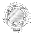
- the single Figure of the drawing shows a cross- sectional view, with parts in elevation, of a bearing, foil mounts and driving ring gear of a preferred embodiment of a hydrodynamic foil bearing in accordance with the present invention.
- an axial shaft 10 is received within a housing 12 of generally cylindrical shape and is surrounded by a series of seven bearing foils 14.
- the foils 14 surround or wrap the shaft 10 in a generally conventional pattern, engaging the surface of shaft 10 in a circumferential series of parallel axial line contacts.
- the foils 14 are cantilevered to the inside of the housing 12, by means to be described below.
- the operation of the shaft 10, with the bearing foils 14 in a given adjusted position is conventional, with ambient air or other fluid being drawn in by mechanism of viscous shear into the wedge-shaped pockets created by the foil wrapping, to produce a supporting gas film between the foils 14 and the shaft 10.
- the cylindrical housing 12 is cylindrical for convenience only: some other housing or support would be feasible, provided that the foils were supported in the same pattern.
- the important element is the wedge-shaped pockets as described.
- the housing 12 contains seven circumferentially evenly spaced, axially extending slots 16 of a generally semi-circular cross-section, and having lengths generally equal to the length of the foils 14. Received within the slots 16 are seven foil mounts consisting of rotatable rods 18. The foils 14 are conventionally anchored into the rods 18 by pins 20. In a conventional bearing, the foils 14 would be anchored by like pins 20, but directly to the inside surface of the cylindrical housing 12. On the outside of each rod 18, and accessible from the outside of the cylindrical housing 12, is an arcuately arranged series of gear teeth 22 all of which are concentrically arranged relative to the centre axis of the shaft 10, and which together constitute the driven portions of the rods 18.
- a ring gear 24 constitutes the drive mechanism, and includes a series of gearteeth 26 which mesh with the gear teeth 22 of the rods 18.
- the ring gear 24 is rotatably supported relative to the housing 12 by any suitable means, not shown.
- a conventional worm gear 28 which could be driven by any suitable means, engages a set of outside gear teeth 30 on the ring gear 24 and releasably turns and holds the ring gear 24 in any desired position relative to the housing 12.
- the ring gear 24 is rotated either clockwise or counterclockwise by the worm gear 28.
- the engagement of the teeth 26 with the teeth 22 in turn rotates the rods 18 within the slots 16, and thereby increases or decreases the bias of the foils 14 against the outside of shaft 10.
- the ring gear 24 may be turned counterclockwise to increase the tension or bias of the foils 14 against the shaft 10. This lifts the shaft 10 away from the bottom of the housing 12 to the extent desired, and supports it until the angular rotational speed of the shaft 10 is enough to create a hydrodynamic fluid support film as described above.
- the ring gear 24 may be turned clockwise to decrease the rubbing force of the foils 14 on the shaft 10.
- housing 12 could be different.
- the rods 18 could be mounted in some other rotatable fashion, the axial slots 16 not being strictly necessary.
- the gear teeth 22 could be located anywhere on the rods 18, for example at the end of the cylindrical housing 12, and could conceivably even be on the other side of the rods 18 and be engageable by a gear with teeth on the outside rather than on the inside thereof. Any other means which would turn and hold the rods 18 simultaneously could also be substituted for the ring gear 24.
Landscapes
- Engineering & Computer Science (AREA)
- General Engineering & Computer Science (AREA)
- Mechanical Engineering (AREA)
- Physics & Mathematics (AREA)
- Fluid Mechanics (AREA)
- Support Of The Bearing (AREA)
Applications Claiming Priority (2)
| Application Number | Priority Date | Filing Date | Title |
|---|---|---|---|
| US06/443,196 US4445792A (en) | 1982-11-22 | 1982-11-22 | Variable preload foil bearing |
| US443196 | 1999-11-19 |
Publications (3)
| Publication Number | Publication Date |
|---|---|
| EP0110531A2 EP0110531A2 (en) | 1984-06-13 |
| EP0110531A3 EP0110531A3 (en) | 1985-08-21 |
| EP0110531B1 true EP0110531B1 (en) | 1986-12-30 |
Family
ID=23759787
Family Applications (1)
| Application Number | Title | Priority Date | Filing Date |
|---|---|---|---|
| EP83306232A Expired EP0110531B1 (en) | 1982-11-22 | 1983-10-14 | Hydrodynamic foil bearing |
Country Status (4)
| Country | Link |
|---|---|
| US (1) | US4445792A (https=) |
| EP (1) | EP0110531B1 (https=) |
| JP (1) | JPS59103017A (https=) |
| DE (1) | DE3368732D1 (https=) |
Families Citing this family (24)
| Publication number | Priority date | Publication date | Assignee | Title |
|---|---|---|---|---|
| FR2527715B1 (fr) * | 1982-05-27 | 1985-10-11 | Abg Semca | Procede de realisation de paliers hydrodynamiques, paliers realises et ensembles accessoires pour la realisation desdits paliers |
| DE3544392A1 (de) * | 1985-12-14 | 1987-06-19 | Kloeckner Humboldt Deutz Ag | Aerodynamisches gleitlager |
| US4815864A (en) * | 1988-05-31 | 1989-03-28 | Williams International Corporation | Adjustable tension foil bearing |
| GB9408485D0 (en) * | 1994-04-27 | 1994-06-22 | Martin James K | Fluid film bearings |
| US5518320A (en) * | 1994-08-18 | 1996-05-21 | The Texas A&M University System | Foil bearing |
| US5519274A (en) * | 1994-09-07 | 1996-05-21 | Rotodynamics-Seal Research, Inc. | Magnetically active foil bearing |
| WO1997002437A1 (en) * | 1995-06-30 | 1997-01-23 | Alliedsignal Inc. | Hybrid foil/magnetic bearing |
| US5752774A (en) * | 1996-10-22 | 1998-05-19 | Mohawk Innovative Technology, Inc. | Zero clearance auxiliary bearing for providing rotor shock tolerance |
| US5915841A (en) | 1998-01-05 | 1999-06-29 | Capstone Turbine Corporation | Compliant foil fluid film radial bearing |
| JP2004084877A (ja) * | 2002-08-28 | 2004-03-18 | Honda Motor Co Ltd | フォイル軸受け |
| JP2004084878A (ja) * | 2002-08-28 | 2004-03-18 | Honda Motor Co Ltd | フォイル軸受け |
| US6964522B2 (en) * | 2004-01-22 | 2005-11-15 | Honeywell International Inc. | Hydrodynamic journal foil bearing system |
| CN100588846C (zh) * | 2007-05-30 | 2010-02-10 | 哈尔滨工业大学 | 可调悬臂式动压气体弹性箔片轴承 |
| GB2464917B (en) * | 2008-10-22 | 2010-09-29 | Rolls Royce Plc | A bearing arrangement |
| KR101131920B1 (ko) | 2010-07-20 | 2012-04-03 | 한국과학기술연구원 | 하이브리드 공기포일베어링 |
| CN102797746A (zh) * | 2012-08-29 | 2012-11-28 | 哈尔滨工业大学 | 一种变节距波箔支撑的油润滑多叶箔片轴承 |
| US20150362012A1 (en) | 2012-11-02 | 2015-12-17 | Yury Ivanovich Ermilov | Foil bearing assembly |
| RU2677435C2 (ru) * | 2013-10-31 | 2019-01-16 | Юрий Иванович Ермилов | Подшипниковый узел (варианты) |
| RU2012146614A (ru) * | 2012-11-02 | 2014-05-10 | Юрий Иванович Ермилов | Подшипниковый узел (варианты) |
| CN103291750B (zh) * | 2013-05-10 | 2015-08-05 | 西安交通大学 | 一种预紧可调的弹性箔片气体轴承 |
| DE102014226840A1 (de) * | 2014-12-22 | 2016-06-23 | Robert Bosch Gmbh | Folienlager, Verfahren zum Einstellen einer Spaltgeometrie eines Folienlagers und entsprechendes Herstellungsverfahren eines Folienlagers |
| US10458875B2 (en) * | 2015-04-22 | 2019-10-29 | Snap-On Equipment Srl A Unico Socio | Holding device for a rim of a vehicle wheel |
| EP3086104B1 (en) * | 2015-04-22 | 2020-10-28 | Snap-on Equipment Srl a unico socio | Holding device for a rim of a vehicle wheel |
| GEAP202215428A (en) * | 2018-10-26 | 2022-01-10 | Andritz Hydro Canada Inc | System and method for radial clearence maintain between variable guide bearing and turbine shaft |
Family Cites Families (4)
| Publication number | Priority date | Publication date | Assignee | Title |
|---|---|---|---|---|
| NL20638C (https=) * | 1926-01-07 | |||
| US3434761A (en) * | 1963-07-11 | 1969-03-25 | Garrett Corp | Hydrodynamic shaft bearing |
| US3506314A (en) * | 1964-08-07 | 1970-04-14 | Ampex | Fluid bearing |
| US3520578A (en) * | 1968-12-05 | 1970-07-14 | Ampex | Journal bearing |
-
1982
- 1982-11-22 US US06/443,196 patent/US4445792A/en not_active Expired - Fee Related
-
1983
- 1983-10-14 EP EP83306232A patent/EP0110531B1/en not_active Expired
- 1983-10-14 DE DE8383306232T patent/DE3368732D1/de not_active Expired
- 1983-11-22 JP JP58218823A patent/JPS59103017A/ja active Granted
Also Published As
| Publication number | Publication date |
|---|---|
| EP0110531A2 (en) | 1984-06-13 |
| US4445792A (en) | 1984-05-01 |
| JPS6229649B2 (https=) | 1987-06-27 |
| JPS59103017A (ja) | 1984-06-14 |
| EP0110531A3 (en) | 1985-08-21 |
| DE3368732D1 (en) | 1987-02-05 |
Similar Documents
| Publication | Publication Date | Title |
|---|---|---|
| EP0110531B1 (en) | Hydrodynamic foil bearing | |
| AU653088B2 (en) | Shaft support assembly for use in a polygon mirror drive motor | |
| US5104287A (en) | Blade tip clearance control apparatus for a gas turbine engine | |
| US5018942A (en) | Mechanical blade tip clearance control apparatus for a gas turbine engine | |
| US4718823A (en) | Pitch changing mechanism for fan blades | |
| GB2235731A (en) | Radial adjustment mechanism for rotor blade tip clearance control apparatus in gas turbines | |
| KR950031399A (ko) | 산업용 로보트 | |
| JPH0365494A (ja) | ブレードピッチ変換装置 | |
| EP0179580A1 (en) | Adjustable stator mechanism for high pressure radial turbines and the like | |
| US3935750A (en) | Counterbalanced mechanical speed-change mechanism | |
| CN215672886U (zh) | 可调静叶联动环限位机构及采用该机构的压气机和发动机 | |
| US6953283B2 (en) | Foil bearing | |
| US4332427A (en) | Air bearing for use with concentric rotary shafts in machines | |
| US3804477A (en) | Centrifugal bearing preload mechanism | |
| US3051019A (en) | Variable speed drive | |
| JPH05138408A (ja) | 高速主軸装置 | |
| GB2211908A (en) | Linear actuator | |
| SU1208279A1 (ru) | Механизм поворота рыбочих лопаток осевой турбомашины | |
| JPS608956Y2 (ja) | スライシングマシンスピンドル | |
| CN210087684U (zh) | 用于调节叶片的同步机构及包括其的发动机 | |
| JPH04248044A (ja) | 雲台の駆動機構 | |
| JPH01220716A (ja) | 微小回転装置 | |
| JPH05111839A (ja) | 旋回テ−ブル | |
| JPH051752A (ja) | 変速装置 | |
| CN114251305A (zh) | 压气机及联动环支撑机构 |
Legal Events
| Date | Code | Title | Description |
|---|---|---|---|
| PUAI | Public reference made under article 153(3) epc to a published international application that has entered the european phase |
Free format text: ORIGINAL CODE: 0009012 |
|
| AK | Designated contracting states |
Designated state(s): DE FR GB |
|
| PUAL | Search report despatched |
Free format text: ORIGINAL CODE: 0009013 |
|
| AK | Designated contracting states |
Designated state(s): DE FR GB |
|
| 17P | Request for examination filed |
Effective date: 19850829 |
|
| 17Q | First examination report despatched |
Effective date: 19860522 |
|
| GRAA | (expected) grant |
Free format text: ORIGINAL CODE: 0009210 |
|
| AK | Designated contracting states |
Kind code of ref document: B1 Designated state(s): DE FR GB |
|
| REF | Corresponds to: |
Ref document number: 3368732 Country of ref document: DE Date of ref document: 19870205 |
|
| ET | Fr: translation filed | ||
| PLBE | No opposition filed within time limit |
Free format text: ORIGINAL CODE: 0009261 |
|
| STAA | Information on the status of an ep patent application or granted ep patent |
Free format text: STATUS: NO OPPOSITION FILED WITHIN TIME LIMIT |
|
| 26N | No opposition filed | ||
| GBPC | Gb: european patent ceased through non-payment of renewal fee | ||
| PG25 | Lapsed in a contracting state [announced via postgrant information from national office to epo] |
Ref country code: FR Free format text: LAPSE BECAUSE OF NON-PAYMENT OF DUE FEES Effective date: 19880630 |
|
| PG25 | Lapsed in a contracting state [announced via postgrant information from national office to epo] |
Ref country code: DE Effective date: 19880701 |
|
| REG | Reference to a national code |
Ref country code: FR Ref legal event code: ST |
|
| PG25 | Lapsed in a contracting state [announced via postgrant information from national office to epo] |
Ref country code: GB Effective date: 19881122 |