EP0109787B1 - Eckumlenkungsstationen für endlose Förderbänder - Google Patents
Eckumlenkungsstationen für endlose Förderbänder Download PDFInfo
- Publication number
- EP0109787B1 EP0109787B1 EP83306609A EP83306609A EP0109787B1 EP 0109787 B1 EP0109787 B1 EP 0109787B1 EP 83306609 A EP83306609 A EP 83306609A EP 83306609 A EP83306609 A EP 83306609A EP 0109787 B1 EP0109787 B1 EP 0109787B1
- Authority
- EP
- European Patent Office
- Prior art keywords
- belt
- run
- cylindrical portion
- angle station
- rectangular
- Prior art date
- Legal status (The legal status is an assumption and is not a legal conclusion. Google has not performed a legal analysis and makes no representation as to the accuracy of the status listed.)
- Expired
Links
Images


Classifications
-
- B—PERFORMING OPERATIONS; TRANSPORTING
- B65—CONVEYING; PACKING; STORING; HANDLING THIN OR FILAMENTARY MATERIAL
- B65G—TRANSPORT OR STORAGE DEVICES, e.g. CONVEYORS FOR LOADING OR TIPPING, SHOP CONVEYOR SYSTEMS OR PNEUMATIC TUBE CONVEYORS
- B65G39/00—Rollers, e.g. drive rollers, or arrangements thereof incorporated in roller-ways or other types of mechanical conveyors
- B65G39/02—Adaptations of individual rollers and supports therefor
-
- B—PERFORMING OPERATIONS; TRANSPORTING
- B65—CONVEYING; PACKING; STORING; HANDLING THIN OR FILAMENTARY MATERIAL
- B65G—TRANSPORT OR STORAGE DEVICES, e.g. CONVEYORS FOR LOADING OR TIPPING, SHOP CONVEYOR SYSTEMS OR PNEUMATIC TUBE CONVEYORS
- B65G15/00—Conveyors having endless load-conveying surfaces, i.e. belts and like continuous members, to which tractive effort is transmitted by means other than endless driving elements of similar configuration
- B65G15/60—Arrangements for supporting or guiding belts, e.g. by fluid jets
-
- B—PERFORMING OPERATIONS; TRANSPORTING
- B65—CONVEYING; PACKING; STORING; HANDLING THIN OR FILAMENTARY MATERIAL
- B65G—TRANSPORT OR STORAGE DEVICES, e.g. CONVEYORS FOR LOADING OR TIPPING, SHOP CONVEYOR SYSTEMS OR PNEUMATIC TUBE CONVEYORS
- B65G39/00—Rollers, e.g. drive rollers, or arrangements thereof incorporated in roller-ways or other types of mechanical conveyors
- B65G39/10—Arrangements of rollers
- B65G39/12—Arrangements of rollers mounted on framework
-
- B—PERFORMING OPERATIONS; TRANSPORTING
- B65—CONVEYING; PACKING; STORING; HANDLING THIN OR FILAMENTARY MATERIAL
- B65G—TRANSPORT OR STORAGE DEVICES, e.g. CONVEYORS FOR LOADING OR TIPPING, SHOP CONVEYOR SYSTEMS OR PNEUMATIC TUBE CONVEYORS
- B65G47/00—Article or material-handling devices associated with conveyors; Methods employing such devices
- B65G47/74—Feeding, transfer, or discharging devices of particular kinds or types
- B65G47/94—Devices for flexing or tilting travelling structures; Throw-off carriages
- B65G47/95—Devices for flexing or tilting travelling structures; Throw-off carriages adapted for longitudinal delivery
-
- B—PERFORMING OPERATIONS; TRANSPORTING
- B65—CONVEYING; PACKING; STORING; HANDLING THIN OR FILAMENTARY MATERIAL
- B65G—TRANSPORT OR STORAGE DEVICES, e.g. CONVEYORS FOR LOADING OR TIPPING, SHOP CONVEYOR SYSTEMS OR PNEUMATIC TUBE CONVEYORS
- B65G2201/00—Indexing codes relating to handling devices, e.g. conveyors, characterised by the type of product or load being conveyed or handled
- B65G2201/04—Bulk
Definitions
- This invention relates to angle stations for endless conveyor belts, according to the preamble of claim 1 (known from US-A-3 184 043).
- U.S. Patent Specification No. 2,222,019 discloses an angle station, comprising co-axial scroll guides each consisting of a support bent into foursided form and having four plane faces successively at included angles of 120° to one another whereby the upper and lower faces are parallel to one another.
- a series of short cambered rollers are mounted on this support so that they define a helical path, one row of similarly oriented rollers being provided on each of the four faces and the rollers being carried by forked bearings mounted on the faces, the outward run of an endless conveyor belt passing in scroll fashion over and under the outside guide and the return run passing in scroll fashion under and over the inner guide.
- British Patent Specification No. 709,019 discloses an angle station comprising belt supporting and centering devices each consisting of a cylindrically or semi-cylindrically shaped supporting beam with two kinds of rotating idler rollers arranged to be outstanding from a flexible mesh bent over the beam to form a curved guide for the belt.
- Such an angle station would be both difficult and expensive to construct, involving, as it does, a large number of short links which have to be machined and pivoted to one another and to the shafts on which the idler rollers rotate, and large number of tension rollers and links which provide cross-ties of the mesh.
- the construction would be insufficiently robust to withstand the rigours which would be encountered when operational especially since the rollers and their bearings would be fully exposed and subject to the deleterious influences of pieces of material tumbling from the belt and of airborne dust.
- U.S. Patent Specification No. 3,184,043 discloses an angle station in which two curved plates are mounted in a framework, the curvatures of the plates being in part-spiral shape about axes one below and at essentially 90° to the other.
- the axis about which each plate is curved is at an angle to one of the sides of the plate such that said one of the sides and a side parallel to it before curvature are after curvature at approximately 90° to one another and are in parallel and vertically-spaced planes.
- Each plate has therein openings in spaced rows parallel to said one side with the openings in one row laterally offset from the openings in an adjacent row and each of the openings has a freely rotatable small roller projecting therethrough.
- An object of the present invention is to provide an angle station enabling the change in direction of the endless conveyor belt to be achieved smoothly with perfect alignment and without distortion of the conveyor belt across its width or undue stress thereon at its longitudinal edges or in the belt-joining means.
- the maximum number of rollers possible must be provided and each must be in a particular relationship one to the other both across the belt width and in the direction of run of the belt so that there will be no significant change in the stress pattern within the conveyor belt and its joints thus maintaining the essential reliability of the belt conveying principle.
- each stationary guide member is of the shape of a major segment of a right-circular cylinder wherein the intersections of the two diagonals of each rectangular opening are interspaced both in parallel rows which extend longitudinally of the respective part-cylindrical portion and in parallel and helical paths and means of each of which extends diagonally of the development of the part-cylindrical portion, and the segments of the curved surfaces of the freely-rotatable small rollers projecting through said openings are in attitude to change the direction of travel of the belt through 90° during passage of the belt about the part-cylindrical portion of the guide member, the rectangular openings being arranged with their longer edges lengthwise of the diagonals representing the mean of the helix but with those of a plurality of the rows nearest to each end of the part-cylindrical portion slightly out of axial symmetry with said diagonals, being slightly inclined in a direction about the intersections to provide a "toe-in" attitude in relation to the line
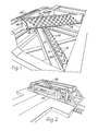
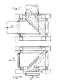
- the inner surfaces 9 and 10, respectively, of the upper and lower runs 11 and 12, respectively, of an endless conveyor belt 13 contact the continuously-changing segments of the curved surfaces of numerous small rollers 14 mounted for free rotation in rectangular openings 15 therefor in the part-cylindrical portions 16, 17, respectively, of upper and lower stationary guide members 18, 19, respectively, each of the shape of a major segment of a right-circular cylinder whereof the axis is in a plane below and parallel to the projected path of travel of the inner surface of the pertaining run 11 or 12 of the belt 13 and extend diagonally of the spaced and parallel vertical planes containing the edges 20, 21 of the respective belt runs 11 and 12.
- the attitudes of the small rollers of each of the two sets to the respective incoming belt run are such as to change through 90° the direction of travel of the belt 13 in contact therewith.
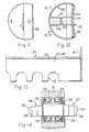
- each of the stationary guide members 18 and 19 is apparent from Fig. 12.
- An insert 25 is fitted into the right-circular cylinder of which the part-cylindrical portion 16 or 17 forms part and is welded in position in the cylinder before the rear portion of same is removed.
- the insert 25 comprises a first rectangular plate 26, of the full length of the cylinder and the major surfaces of which are in minor chordal planes of the cylinder, second and third rectangular plates 27 and 28 also of the full length of the cylinder and which are perpendicular to the plate 26, spaced symmetrically about the diametral plane DPI normal to that DP2 to which the plate 26 is parallel and of width to bridge between the plate 26 and the inner peripheral surface 29 of the cylinder, and a stiffening bar 30 bridging between and welded to the plates 27 and 28, the bar 30 also being parallel to the diametral plane DP2 and being positioned midway between the plate 26 and that portion of said surface 29 intercepted by the plates 27 and 28.
- the openings 15 are formed in the cylinder peripheral wall and notches 35 are formed in those longitudinal edges of the plates 27 and 28 to be juxtaposed to the inner peripheral surface 29 of the cylinder, before the insert 25 is positioned within the cylinder and welded thereto. Moreover the notches 35 are formed in the plates 27 and 28 and elongate openings 36 are formed in the plate 26, before the insert 25 is assembled.
- the openings 36 have rounded ends and are symmetrically staggered about the longitudinal axis of the plate 26 with their longitudinal axes parallel to that of the plate 26.
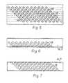
- the rectangular openings 15 are located with the inter-sections 40 of the two diagonals of each interspaced both in parallel rows which extend longitudinally of the part-cylindrical portion 16 or 17 and in parallel and helical paths the means of each of which extends diagonally of the development of the part-cylindrical portion (Fig. 5).
- the openings 15 are arranged with their longer edges lengthwise of the diagonals representing the means of the helix but the four rows nearest to each end are slightly out of axial symmetry with said diagonals, being slightly inclined in a direction about the intersections 40 to provide a "toe-in" attitude in relation to the line of run of an endless conveyor belt.
- Round holes 45 and 46 are drilled through the part-cylindrical portions 16 and 17, one at each side of each of the openings 15 with the axis of the holes in the plane passing through the respective intersection 40 and normal to the longer edges of each respective rectangular opening 15.
- the holes 45 and 46 at each side of each opening 15 are spot faced at their outer ends just deep enough to develop about the respective hole 45 or 46 a complete annulus having a flat bottom in a plane normal to the axis of the hole.
- each roller 14 (Fig. 14) comprises a spindle 50, a roller shell 51, deep groove ball bearings 52, 53 between the spindle 50 and the shell 51, sealing washers 54 at the outer faces of the ball bearings 52, 53 and external circlips 55 preventing axial displacement of the ball bearings 52, 53.
- the elongate openings 36 in the plates 26 are for enabling access to be had for the positioning of the rollers 14 from within the guide members 18, 19.
- the surface areas 56, 57 of the roller spindles 50 are shaped to bear snugly against the inner peripheral surface 29 of the part-cylindrical portion 16 or 17 of the stationary guide member 18 or 19 about the peripheries of the respective round holes 45 and 46. Tapered holes 58, 59 through the spindles 50 are then engaged from the outside by the threaded stems of screws 60 the heads of which are flush in the annuli about the round holes 45 and 46.
- Temporary end discs 61 are fillet welded to each insert 25 (see Fig. 13) to provide a means of measuring accurately the effective diameter of insert 25 which otherwise could not be gauged.
- the end discs 61 are removed before the insert 25 is located within the respective cylinder.
- the notches 35 must be axially central with the intersections 40 of the two diagonals of the respective openings 15.
- Each insert is fully welded to the inner peripheral surface 29 of the cylinder before the minor part-cylindrical portion of the latter is removed.
- End covers 62 are secured to the ends of the guide members 18, 19.
- the inner surface 9 of the upper run 11 of the endless conveyor belt 13 contacts those curved surfaces of segments of the numerous freely-rotatable small rollers 14 (hidden by the belt in Fig. 4) which are proud of the part-cylindrical portion of the upper stationary guide and the direction of travel of the upper run is changed through 90° due to the attitudes of the small rollers 14.
- the inner surface 9 Prior to contacting the small rollers 14 of the upper stationary guide member 18, the inner surface 9 runs over small rollers 14' on a stationary guide transverse of the belt (Fig. 1).
- the guide transverse of the belt comprises a series of spaced small rollers 14' mounted in axial alignment across a plate free to swivel within limits about its vertical centre of symmetry.
- the belt may be steered so as to approach the upper stationary guide member 18 in a central position.
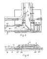
- the belt surfaces On leaving the upper stationary guide member 18, the belt surfaces are reversed and the belt passes about a first guide roller 65 and then over a second guide roller 66 so that the belt surfaces are restored to their original dispositions when the belt emerges from the angle station.
- the inner surface 10 of the lower run 12 of the endless conveyor belt passes below a third guide roll 67 and over a fourth guide roll 68 so that the outer surface of said lower run 12 contacts the continuously-changing segments of those curved surfaces of the numerous freely-rotatable small rollers 14 which are proud of the part-cylindrical portion of the lower stationary guide member 19 and the direction of travel of the lower run is changed through 90° and the belt surfaces are reversed on the lower run 12 of the belt leaving the lower stationary guide member 19 to be then again directly below the upper run 11.
- Material such as coal will be thrown off the incoming upper run of the belt on passage thereof about the upper stationary guide member 18 and fall on to the outgoing run of the upper run of the belt (see Fig. 3).
- the angle station may be so assembled that it can be arranged on the level to accept belt entry thereinto from any given direction normal to the entry roller and direct belt exit therefrom either on the level or at a dipping or rising inclination after undergoing a change of direction through 90° either to the right or to the left.
- Figs. 15 to 18 the two roller banks and support beams are denoted X and Y and the incoming and outgoing runs of the endless conveyor belt are denoted 70 and 71, respectively.
- Fig. 16 the incoming run 70 approaches from the 6 o'clock direction and the outgoing run 71 departs again in the 3 o'clock direction.
- the roller banks with their support beams are transposed and each is then rotated through 180° about its axis, and the guide roller 72 and 73 associated with the incoming run 70 and its return 70A are transferred to the new intake side of the angle station.
- the Fig. 18 arrangement is achieved by rotating the entire angle station through 180° from the Fig. 15 arrangement to cater for the incoming run 70 approaching from the 6 o'clock direction and the outgoing run 71 exiting in the 9 o'clock direction.
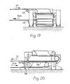
- Fig. 19 shows in end elevation the guide roller 72 at intake of the incoming run 70, and the arrangement of the guide roller 72 is appropriate whether the approach of the incoming run is on the level or at a rising inclination.
- the arrangement of the guide roller 73 for the return run 70A is also constant.
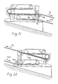
- the arrangements of the guide rollers at exit and return of the outgoing run 71 differ according to whether the outgoing run 71 and the return run 71A are on the level or at a dipping or rising inclination.
- the outgoing run 71 and the return run 71A are on the level and the guide rollers 74 and 75 respectively therefor are as shown in end elevation in Fig. 20.
- the arrangements of the guide rollers 74 and 75 for a dipping inclination of the outgoing run 71 and a rising inclination of the return run 71A are the same as in Fig. 20, but, in the Fig.
- the guide roller 74A with its mounting for the return run 71A is similar to the guide roller 74 with its mounting in the Figs. 20 and 21 arrangements, but inverted.
- FIGs. 20 to 22 Also shown in Figs. 20 to 22 is an impact plate 76 disposed within the angle station below the closely outgoing run 71 to prevent undue flexure of the belt on material such as coal falling from the incoming run on to the outgoing run.
- the plate 76 is on the level in Figs. 20 and 21 but is inclined upwardly with the outgoing run 71 of the belt in the Fig. 22 arrangement.
- angle stations shown and described are intended for changes in direction of an endless conveyor belt through 90°, they could be constructed to cater for belt changes in direction through angles between 85° and 95° but this would necessitate appropriate modification of the helical paths.
Landscapes
- Engineering & Computer Science (AREA)
- Mechanical Engineering (AREA)
- Structure Of Belt Conveyors (AREA)
Claims (10)
Applications Claiming Priority (2)
| Application Number | Priority Date | Filing Date | Title |
|---|---|---|---|
| GB8232119 | 1982-11-10 | ||
| GB8232119 | 1982-11-10 |
Publications (2)
| Publication Number | Publication Date |
|---|---|
| EP0109787A1 EP0109787A1 (de) | 1984-05-30 |
| EP0109787B1 true EP0109787B1 (de) | 1986-12-30 |
Family
ID=10534168
Family Applications (1)
| Application Number | Title | Priority Date | Filing Date |
|---|---|---|---|
| EP83306609A Expired EP0109787B1 (de) | 1982-11-10 | 1983-10-31 | Eckumlenkungsstationen für endlose Förderbänder |
Country Status (9)
| Country | Link |
|---|---|
| US (1) | US4655340A (de) |
| EP (1) | EP0109787B1 (de) |
| AU (1) | AU570932B2 (de) |
| BR (1) | BR8306161A (de) |
| DE (1) | DE3368581D1 (de) |
| IN (1) | IN160513B (de) |
| MX (1) | MX159240A (de) |
| PL (1) | PL135329B1 (de) |
| ZA (1) | ZA838297B (de) |
Families Citing this family (13)
| Publication number | Priority date | Publication date | Assignee | Title |
|---|---|---|---|---|
| GB2156760B (en) * | 1984-04-07 | 1987-12-31 | Anderson Strathclyde Plc | Angle stations in or for endless conveyor belts |
| US4987994A (en) * | 1989-06-12 | 1991-01-29 | Pre-Engineered Components, Inc. | Spur conveyor assembly |
| US5083657A (en) * | 1989-06-12 | 1992-01-28 | Richard W. Kelsey | Spur conveyor assembly |
| GB9119572D0 (en) * | 1991-09-13 | 1991-10-23 | Huwood Ltd | Angle stations in or for endless conveyor belts |
| GB9610403D0 (en) * | 1996-05-17 | 1996-07-24 | Huwood Int Ltd | Angle station |
| EP0980843A3 (de) | 1998-08-18 | 2002-01-30 | Masao Kubota | Durchgehender und wendelbarer Beförderer |
| US7234588B1 (en) * | 2005-12-13 | 2007-06-26 | Fki Logistex Inc. | Merge conveyor |
| US8556065B2 (en) * | 2010-02-17 | 2013-10-15 | Stephen William Armstrong | Content display for use with conveyor systems |
| US8701874B2 (en) * | 2012-06-08 | 2014-04-22 | Interroll Holding Ag | Conveyor |
| CN104176458A (zh) * | 2014-09-03 | 2014-12-03 | 徐州天科机械制造有限公司 | 一种带式输送机任意角转弯装置的胶带转向方法 |
| CN104176457A (zh) * | 2014-09-03 | 2014-12-03 | 徐州天科机械制造有限公司 | 一种带式输送机任意角转弯装置的胶带转向滚筒 |
| CN106865146A (zh) * | 2017-04-27 | 2017-06-20 | 安徽华宏机械设备有限公司 | 一种便于镶嵌耐磨块的输送机滚筒 |
| CN110155606A (zh) * | 2019-06-12 | 2019-08-23 | 浙江申振机械科技有限公司 | 一种皮带传送转弯机结构 |
Family Cites Families (20)
| Publication number | Priority date | Publication date | Assignee | Title |
|---|---|---|---|---|
| GB433756A (en) * | 1935-02-01 | 1935-08-20 | T & T Vicars Ltd | Improvements in conveyors |
| US2222019A (en) * | 1938-10-31 | 1940-11-19 | Mavor & Coulson Ltd | Conveyer of the endless belt type |
| US2369479A (en) * | 1943-01-25 | 1945-02-13 | Evelyn Michna | Conveyer mechanism |
| US2561708A (en) * | 1946-07-29 | 1951-07-24 | Milik Conveyors Ltd | Angle station for belt conveyers |
| DE867517C (de) * | 1949-03-01 | 1953-02-19 | Rudolf Milik | Eckfuehrung von Foerderbaendern |
| GB709019A (en) * | 1951-06-20 | 1954-05-12 | Franciszek Gawenda | Variable angle belt deflector for belt conveyors |
| DE932415C (de) * | 1953-05-06 | 1955-09-01 | Rheinelbe Bergbau Ag | Bandfuehrung an Antriebsstationen fuer Foerderbaender |
| US2861675A (en) * | 1954-02-09 | 1958-11-25 | Cordis Nat | Continuous web-type poultry feeder |
| US2798590A (en) * | 1954-09-10 | 1957-07-09 | Seymour H Raskin | Direction-changing device for conveyor |
| DE1038477B (de) * | 1955-08-02 | 1958-09-04 | Eisen & Stahlind Ag | Vorrichtung zur Sicherung des Geradlaufs des Fordergurtes bei Bandanlagen |
| US2828852A (en) * | 1955-12-27 | 1958-04-01 | United States Steel Corp | Roller conveyor |
| US3016127A (en) * | 1956-10-19 | 1962-01-09 | Jones & Laughlin Steel Corp | Belt conveyor apparatus |
| GB919544A (en) * | 1958-07-11 | 1963-02-27 | Coal Industry Patents Ltd | Improvements in or relating to conveyor systems having endless flexible conveying members |
| DE1128358B (de) * | 1960-02-11 | 1962-04-19 | Hans Ziller | Eckfuehrung fuer Foerderbaender |
| US3184043A (en) * | 1961-07-07 | 1965-05-18 | Coal Industry Patents Ltd | Conveyor systems |
| US3203536A (en) * | 1961-09-11 | 1965-08-31 | Herbert S Shaw | Cornering roller for belts |
| GB1048256A (en) * | 1962-09-11 | 1966-11-16 | Coal Industry Patents Ltd | Improvements in angle stations for endless conveyor belts |
| US3319767A (en) * | 1965-03-04 | 1967-05-16 | Charles E Breternitz | Impact compensating means for belt conveyors |
| US3661246A (en) * | 1970-03-26 | 1972-05-09 | Hewitt Robins Inc | Training idler |
| DE2948290A1 (de) * | 1979-11-30 | 1981-06-04 | Agfa-Gevaert Ag, 5090 Leverkusen | Vorrichtung zum umlenken einer bewegten materialbahn |
-
1983
- 1983-10-31 EP EP83306609A patent/EP0109787B1/de not_active Expired
- 1983-10-31 DE DE8383306609T patent/DE3368581D1/de not_active Expired
- 1983-11-02 IN IN733/DEL/83A patent/IN160513B/en unknown
- 1983-11-04 US US06/548,627 patent/US4655340A/en not_active Expired - Fee Related
- 1983-11-08 ZA ZA838297A patent/ZA838297B/xx unknown
- 1983-11-08 AU AU21065/83A patent/AU570932B2/en not_active Ceased
- 1983-11-09 BR BR8306161A patent/BR8306161A/pt not_active IP Right Cessation
- 1983-11-09 MX MX199347A patent/MX159240A/es unknown
- 1983-11-10 PL PL1983244497A patent/PL135329B1/pl unknown
Also Published As
| Publication number | Publication date |
|---|---|
| PL135329B1 (en) | 1985-10-31 |
| BR8306161A (pt) | 1984-06-12 |
| EP0109787A1 (de) | 1984-05-30 |
| AU570932B2 (en) | 1988-03-31 |
| IN160513B (de) | 1987-07-18 |
| MX159240A (es) | 1989-05-08 |
| DE3368581D1 (en) | 1987-02-05 |
| US4655340A (en) | 1987-04-07 |
| ZA838297B (en) | 1984-07-25 |
| AU2106583A (en) | 1984-05-17 |
| PL244497A1 (en) | 1984-07-16 |
Similar Documents
| Publication | Publication Date | Title |
|---|---|---|
| EP0109787B1 (de) | Eckumlenkungsstationen für endlose Förderbänder | |
| US5667054A (en) | Conveyor | |
| US5012914A (en) | Diverter assembly for article conveyor | |
| JPH07309413A (ja) | 分岐合流用コンベヤ設備 | |
| US3429422A (en) | Belt conveyor | |
| US4328889A (en) | Conveyor means | |
| KR900007306A (ko) | 계란 수집장치 | |
| EP0077748B1 (de) | Förderer | |
| AU572649B2 (en) | Angle sataions for endless belt conveyors | |
| EP0081574B1 (de) | Vertikalförderer mit kippbaren trägern | |
| CA2021526A1 (en) | Apparatus for conveying grain | |
| CA1218028A (en) | Angle stations in or for endless conveyor belts | |
| US4986413A (en) | Conveyor belt inversion device | |
| US2856060A (en) | Conveyor of transversely varying width | |
| US4440294A (en) | Conveyor | |
| US2762496A (en) | Roller flight conveyor | |
| US4378874A (en) | Pallet elevator for a ship | |
| EP0603254B1 (de) | Umlenkungsstation | |
| US2990052A (en) | Conveyor | |
| JPS61174020A (ja) | ベルトコンベア | |
| US5367352A (en) | Direction-changing roller for suspension frames of photographic material developing machines | |
| GB1593617A (en) | Conveyor turntables | |
| US3184043A (en) | Conveyor systems | |
| KR200237476Y1 (ko) | 벨트의사행에따라위치가가변되는스커트장치 | |
| JPH0323442B2 (de) |
Legal Events
| Date | Code | Title | Description |
|---|---|---|---|
| PUAI | Public reference made under article 153(3) epc to a published international application that has entered the european phase |
Free format text: ORIGINAL CODE: 0009012 |
|
| AK | Designated contracting states |
Designated state(s): BE DE FR GB NL |
|
| 17P | Request for examination filed |
Effective date: 19840704 |
|
| GRAA | (expected) grant |
Free format text: ORIGINAL CODE: 0009210 |
|
| AK | Designated contracting states |
Kind code of ref document: B1 Designated state(s): BE DE FR GB NL |
|
| REF | Corresponds to: |
Ref document number: 3368581 Country of ref document: DE Date of ref document: 19870205 |
|
| ET | Fr: translation filed | ||
| PLBE | No opposition filed within time limit |
Free format text: ORIGINAL CODE: 0009261 |
|
| STAA | Information on the status of an ep patent application or granted ep patent |
Free format text: STATUS: NO OPPOSITION FILED WITHIN TIME LIMIT |
|
| 26N | No opposition filed | ||
| NLT1 | Nl: modifications of names registered in virtue of documents presented to the patent office pursuant to art. 16 a, paragraph 1 |
Owner name: ANDERSON GROUP PLC TE GLASGOW, GROOT-BRITTANNIE. |
|
| REG | Reference to a national code |
Ref country code: FR Ref legal event code: CD |
|
| PGFP | Annual fee paid to national office [announced via postgrant information from national office to epo] |
Ref country code: NL Payment date: 19921031 Year of fee payment: 10 |
|
| PGFP | Annual fee paid to national office [announced via postgrant information from national office to epo] |
Ref country code: FR Payment date: 19921104 Year of fee payment: 10 |
|
| PGFP | Annual fee paid to national office [announced via postgrant information from national office to epo] |
Ref country code: DE Payment date: 19921106 Year of fee payment: 10 |
|
| PGFP | Annual fee paid to national office [announced via postgrant information from national office to epo] |
Ref country code: BE Payment date: 19921130 Year of fee payment: 10 |
|
| PG25 | Lapsed in a contracting state [announced via postgrant information from national office to epo] |
Ref country code: BE Effective date: 19931031 |
|
| BERE | Be: lapsed |
Owner name: ANDERSON GROUP P.L.C. Effective date: 19931031 |
|
| PG25 | Lapsed in a contracting state [announced via postgrant information from national office to epo] |
Ref country code: NL Effective date: 19940501 |
|
| NLV4 | Nl: lapsed or anulled due to non-payment of the annual fee | ||
| PG25 | Lapsed in a contracting state [announced via postgrant information from national office to epo] |
Ref country code: FR Effective date: 19940630 |
|
| PG25 | Lapsed in a contracting state [announced via postgrant information from national office to epo] |
Ref country code: DE Effective date: 19940701 |
|
| REG | Reference to a national code |
Ref country code: FR Ref legal event code: ST |
|
| PGFP | Annual fee paid to national office [announced via postgrant information from national office to epo] |
Ref country code: GB Payment date: 19941031 Year of fee payment: 12 |
|
| PG25 | Lapsed in a contracting state [announced via postgrant information from national office to epo] |
Ref country code: GB Effective date: 19951031 |
|
| GBPC | Gb: european patent ceased through non-payment of renewal fee |
Effective date: 19951031 |